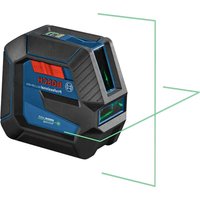
GRL1000-20HV Professional - Laser level BOSCH - Free user manual and instructions
Find the device manual for free GRL1000-20HV Professional BOSCH in PDF.

| Product type | Rotary laser level |
| Brand | Bosch |
| Model | GRL1000-20HV Professional |
| Dimensions (L x W x H) | 190 x 180 x 170 mm |
| Weight | 1.76 kg |
| Power supply | 2 alkaline batteries 1.5 V LR20 (type D) |
| Battery life | Approx. 50 h |
| Working area (with receiver) | Up to 300 m diameter |
| Leveling accuracy | ±3 mm at 30 m |
| Self-leveling range | ±5° (8%) |
| Typical leveling time | 15 s |
| Rotation speed | 150/300/600 min⁻¹ |
| Sweep angle (line mode) | 10°/25°/50° |
| Laser class | 3R |
| Laser type | 635 nm, <5 mW |
| Output beam diameter | Approx. 4 mm |
| Tripod thread | 5/8 in - 11 |
| Protection rating | IP54 (dust and splash water protected) |
| Operating temperature | 0 °C to +50 °C |
| Storage temperature | -20 °C to +70 °C |
| Main functions | Automatic leveling, rotation mode, line tracing, point marking, shock alert, remote control, laser receiver |
| Maintenance and cleaning | Clean with a soft, damp cloth, without detergents or solvents. Do not immerse. |
| Safety | Do not look directly into the laser beam. Keep away from pacemakers and magnetic supports. |
| Spare parts and repairability | Repair exclusively by an authorized Bosch service center using original parts. |
Frequently Asked Questions - GRL1000-20HV Professional BOSCH
User questions about GRL1000-20HV Professional BOSCH
0 question about this device. Answer the ones you know or ask your own.
Ask a new question about this device
Download the instructions for your Laser level in PDF format for free! Find your manual GRL1000-20HV Professional - BOSCH and take your electronic device back in hand. On this page are published all the documents necessary for the use of your device. GRL1000-20HV Professional by BOSCH.
USER MANUAL GRL1000-20HV Professional BOSCH
IMPORTANT: IMPORTANT : IMPORTANTE: Read Before Using Lire avant usage Leer antes de usar

Operating/Safety Instructions
Consignes de fonctionnement/sécurité
Instrucciones de funciona y seguidad
GRL800-20HV
GRL900-20HV
GRL1000-20HV
LR30
LR10
RC1

BOSCH
Call Toll Free for Consumer Information & Service Locations
The definitions below describe the level of severity for each signal word. Please read the manual and pay attention to these symbols.
| ! | This is the safety alert symbol. It is used to alert you to potential personal injury hazards. Obey all safety messages that follow this symbol to avoid possible injury or death. |
| Read manual symbol - Alerts user to read manual. | |
| ▲WARNING | WARNING indicates a hazardous situation which, if not avoided, could result in death or serious injury. |
| FC | This symbol designates that this laser leveling tool complies with Part 15 of the FCC Rules. |
General Safety Rules
WARNING
Read all instructions. Failure to follow all instructions listed below may result in hazardous radiation exposure, electric shock, fire and/or
serious injury.
SAVE ALL WARNING AND INSTRUCTIONS FOR FUTURE REFERENCE
The term "tool" in all of the warnings listed below refers to your mains-operated (corded) tool or battery-operated (cordless) tool.
WARNING
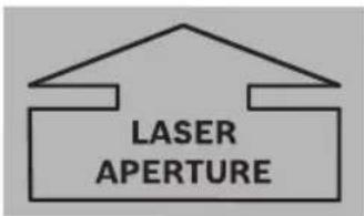
The following labels are on your laser tool for your convenience and safety. They indicate where the laser light is emitted by the tool.
ALWAYS BE AWARE of their location when using the tool.
GRL800-20HVGRL900-20HV/GRL1000-20HVGRL900-20HV/GRL1000-20HV
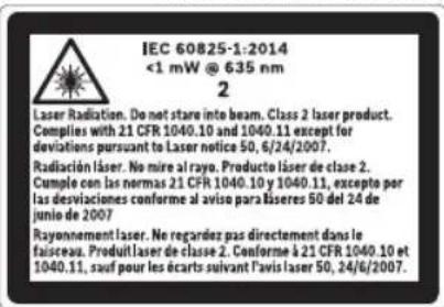

Do not direct the laser beam at persons or animals and do not stare into the laser beam yourself. This tool produces laser class 2 (GRL800-20HV) laser radiation and complies with 21 CFR 1040.10 and 1040.11 except for deviations pursuant to Laser Notice No. 50, dated June 24, 2007. This can lead to persons being blinded.

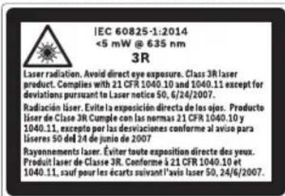
Do not direct the laser beam at persons or animals and avoid direct eye exposure. This tool produces laser class 3R laser radiation (GRL900-20HV/ GRL1000-20HV) and complies with 21 CFR 1040.10 and 1040.11 except for deviations pursuant to Laser Notice No. 50, dated June 24, 2007. This can lead to persons being blinded.
DO NOT remove or deface any warning or caution labels. Removing labels increases the risk of exposure to laser radiation.
Use of controls or adjustments or performance of procedures other than those specified in this manual, may result in hazardous radiation exposure.
ALWAYS make sure that any bystanders in the vicinity of use are made aware of the dangers of looking directly into the laser tool.
DO NOT place the laser tool in a position that may cause anyone to stare into the laser beam intentionally or unintentionally. Serious eye injury could result.
ALWAYS position the laser tool securely. Damage to the laser tool and/or serious injury to the user could result if the laser tool fails.
ALWAYS use only the accessories that are recommended by the manufacturer of your laser tool. Use of accessories that have been designed for use with other laser tools could result in serious injury.
DO NOT use this laser tool for any purpose other than those outlined in this manual. This could result in serious injury.
DO NOT leave the laser tool "ON" unattended in any operating mode.
DO NOT disassemble the laser tool. There are no user serviceable parts inside. Do not modify the product in any way. Modifying the laser tool may result in hazardous laser radiation exposure.
DO NOT use the laser viewing glasses as safety goggles. The laser viewing glasses are used for improved visualization of the laser beam, but they do not protect against laser radiation.
DO NOT use the laser viewing glasses as sun glasses or in traffic. The laser viewing glasses do not afford complete UV protection and reduce color perception.
DO NOT use any optical tools such as, but not limited to, telescopes or transits to view the laser beam. Serious eye injury could result.
DO NOT stare directly at the laser beam or project the laser beam directly into the eyes of others. Serious eye injury could result.
Work area safety
Keep work area clean and well lit. Cluttered or dark areas invite accidents.
DO NOT operate the laser tool around children or allow children to operate the laser tool. Serious eye injury could result. DO NOT use laser tools, attachments and
accessories outdoors when lightning conditions are present.
Do not operate the laser tool in explosive environments, such as in the presence of flammable liquids, gases or dusts. Sparks can be created in the laser tool which may ignite the dust or fumes.
Electrical safety
WARNING
Batteries can explode or leak, cause injury or fire.
To reduce this risk, always follow all instructions and warnings on the battery label and package.
DO NOT expose the laser tool and battery to rain or wet conditions. Water entering laser tool will increase the risk of fire and personal injury.
DO NOT short any battery terminals.
DO NOT charge alkaline batteries.
DO NOT mix old and new alkaline batteries. Replace all of them at the same time with new batteries of the same brand and type.
DO NOT mix battery chemistries.
Dispose of or recycle batteries per local code.
DO NOT dispose of batteries in fire.
Keep batteries out of reach of children.
Remove batteries if the device will not be used for several months.
Personal safety
If laser radiation strikes your eye, you must deliberately close your eyes and immediately turn your head away from the beam.
Do not make any modifications to the laser equipment.
Stay alert, watch what you are doing and use common sense when operating a tool. Do not use a tool while you are tired or under the influence of drugs, alcohol or medication. A moment of inattention while operating a tool may result in serious personal injury or incorrect measurement results.
Use safety equipment. Always wear eye protection. Safety equipment such as dust mask, non-skid safety shoes, hard hat, or hearing protection used for appropriate conditions will reduce personal injuries.
Use caution when using laser tools in the vicinity of electrical hazards.
Magnets

Keep the tool, wall mount (25), laser receiver LR10, LR30 (23, 13), and laser target plate (29) away from cardiac pacemakers.
The magnets of the tool and laser
target plate generate a field that can impair the function of cardiac pacemakers.
Keep the tool, wall mount (25), laser receiver LR10, LR30 (23, 13), and laser target plate (29) away from magnetic data medium and magnetically-sensitive equipment. The effect of the magnets of the tool and laser target plate can lead to irreversible data loss.
Use and care
Use the correct tool for your application. The correct tool will do the job better and safer.
Do not use the tool if the switch does not turn it on and off. Any tool that cannot be controlled with the switch is dangerous and must be repaired.
Store idle tool out of the reach of children and do not allow persons unfamiliar with the tool or these instructions to operate the tool. Tools are dangerous in the hands of untrained users.
Maintain tools. Check for misalignment or binding of moving parts, breakage of parts and any other condition that may affect the operation. If damaged, have the tool repaired before use. Many accidents are caused by poorly maintained tools.
Use the tool, accessories, etc., in accordance with these instructions and in the manner intended for the particular type of tool, taking into account the working conditions and the work to be performed. Use of the tool for operations different from those intended could result in a hazardous situation.
Battery tool use and care
Recharge only with the charger specified by the manufacturer. A charger that is suitable for one type of battery pack may create a risk of fire when used with another battery pack.
Use laser tools only with specifically designated battery packs. Use of any other battery packs may create a risk of injury and fire.
When battery pack is not in use, keep it away from other metal objects like paper clips, coins, keys, nails, screws, or other small metal objects that can make a connection from one terminal to another. Shorting the battery terminals together may cause burns or fire.
Under abusive conditions, liquid may be ejected from the battery; avoid contact. If contact accidentally occurs, flush with water. If liquid contacts eyes, additionally seek medical help. Liquid ejected from the battery may cause irritation or burns.
Do not use a battery pack or tool that is damaged or modified. Damaged or modified batteries may exhibit unpredictable behavior resulting in fire, EXPLOSION or risk of injury.
Do not expose a battery pack or tool to fire or excessive temperature. Exposure to fire or temperature above 265^ (130^) may cause explosion.
Follow all charging instructions and do not charge the battery pack or tool outside the temperature range specified in the instructions. Charging improperly or at temperatures outside the specified range may damage the BATTERY and increase the risk of fire.
Service
Have your tool serviced by a qualified repair person using only identical replacement parts. This will ensure that the safety of the tool is maintained.
Develop a periodic maintenance schedule for tool. When cleaning a tool be careful not to disassemble any portion of the tool since internal wires may be misplaced or pinched or may be improperly mounted. Certain cleaning agents such as gasoline, carbon tetrachloride, ammonia, etc., may damage plastic parts.
SAVE THESE INSTRUCTIONS.
FCC Caution

The manufacturer is not responsible for radio interference caused by unauthorized modifications to
this equipment. Such modifications could void the user's authority to operate the equipment.
This device complies with Part 15 of the FCC Rules. Operation is subject to the following two conditions:
1) This device may not cause harmful interference, and
2) This device must accept any interference received, including interference that may cause undesired operation.
NOTE! This equipment has been tested and found to comply with the limits for a Class B digital devices, pursuant to Part 15 of the FCC rules. These limits are designed to provide reasonable protection against harmful interference in a residential installation. This equipment generates uses and can radiate radio frequency energy and, if not installed and used in accordance with the instructions, may cause harmful interference to radio communications. However, there is no guarantee
that interference will not occur in a particular installation. If this equipment does cause harmful interference to radio or television reception, which can be determined by turning the equipment off and on, the user is encouraged to try to correct the interference by one or more of the following measures:
Reorient or relocate the receiving antenna.
- Increase the separation between the equipment and receiver.
- Connect the equipment into an outlet on a circuit different from that to which the receiver is connected.
- Consult the dealer or an experienced radio/ TV technician for help.
"Exposure to Radio Frequency (RF) Signals: The wireless device is a radio transmitter and receiver. It is designed and manufactured not to exceed the emission limit for exposure to radio frequency (RF) energy set by the Ministry of Health (Canada), Safety Code 6. These limits are part of comprehensive guidelines and established permitted levels of RF energy for the general population.
Industry Canada (IC)
This device complies with Industry Canada's licence-exempt RSSs. Operation is subject to the following two conditions:
(1) This device may not cause interference; and
(2) This device must accept any interference, including interference that may cause undesired operation of the device.
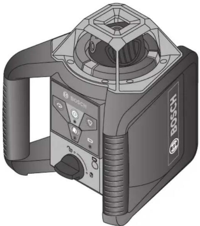
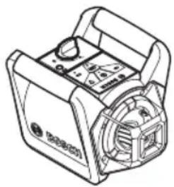
Features
The numbering of the product features shown refers to the illustration of the laser tool on the graphic pages 2, 3, and 5.
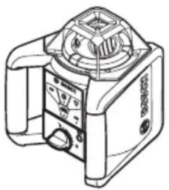
1 Shock-warning indicator
2 Shock-warning button
3 Automatic leveling indicator
4 On/Off button
5 Rotational speed selection
6 Variable laser beam
7 Reception lens for remote control
8 Exit opening for laser beam
9 Plumb beam
10 Rotation head
11 Line operation and length selection
12 Low Battery indicator
13 LR30 Laser Receiver*
14 Battery compartment
15 Battery compartment lock
16 5/8-11 tripod mount
17 Serial number
18 Laser warning label
19 Warning label, laser radiation exit opening (GRL900-20HV, GRL1000-20HV only)
20 Remote control
21 Tripod
22 Leveling rod
23 LR10 Laser receiver
24 Laser viewing glasses
25 Wall mount/alignment unit
26 Wall mount fastening screw
27 Wall mount locking screw
28 5/8-11 instrument mount
29 Ceiling measurement plate
30 Case
*Illustrated accessory may be optional on some models and not included in standard package.
Rotational Laser Level GRL800-20HV GRL900-20HV GRL1000-20HV
| Working range (Diameter) | |||
| -without laser receiver | approx. 200 ft (approx. 60 m) | approx. 200 ft (approx. 60 m) | approx. 200 ft (approx. 60 m) |
| -with laser receiver | approx. 800 ft (approx. 240 m) | approx. 1000 ft (approx. 300 m) | approx. 1000 ft (approx. 300 m) |
| Leveling Accuracy1)2) ±3/16 in at 100 ft (±4.5 mm at 30 m) | ±1/8 in at 100 ft (±3 mm at 30 m) | ±1/8 in at 100 ft (±3 mm at 30 m) | |
| Self-leveling range (typical) ±8% (±5°) ±8% (±5°) ±8% (±5°) | |||
| Leveling duration (typical) 15s 15s 15s | |||
| Rotational speed 150/300/600min | -1 | 150/300/600min-1 | 150/300/600min-1 |
| Scan angle for line operation 0°/10°/25°/50° 0°/10°/25°/50° 0°/10°/25°/50° | |||
| Operating temperature 14°F ~122°F (-10°C ~ +50°C) | 14°F ~122°F (-10°C ~ +50°C) | 14°F ~122°F (-10°C ~ +50°C) | |
| Storage temperature -4°F ~ 158°F (-20°C ~ +70°C) | -4°F ~ 158°F (-20°C ~ +70°C) | -4°F ~ 158°F (-20°C ~ +70°C) | |
| Relative air humidity, max. | 90 % | 90 % | 90 % |
| Laser class | 2 | 3R | 3R |
| Laser type | 635 nm, <1 mW | 635 nm, <5 mW | 635 nm, <5 mW |
| Laser beam Ø at the exit opening, approx.1) | .2 in (4 mm) | .2 in (4 mm) | .2 in (4 mm) |
| Tripod mount | 5/8 in-11 | 5/8 in-11 | 5/8 in-11 |
| Batteries (alkali-manganese) | 2 x 1.5 VD (LR20) | 2 x 1.5 VD (LR20) | 2 x 1.5 VD (LR20) |
| Operating life time, approx. -Batteries (alkali-manganese)1) | 50 h | 50 h | 50 h |
| Weight | 3.9 lb (1.76 kg) | 3.9 lb (1.76 kg) | 3.9 lb (1.76 kg) |
| Dimensions | 7.5 x 7 x 6.7 in (190 x 180 x 170 mm) | 7.5 x 7 x 6.7 in (190 x 180 x 170 mm) | 7.5 x 7 x 6.7 in (190 x 180 x 170 mm) |
| Degree of protection | IP 54 (dust and splash water protected) | IP 54 (dust and splash water protected) | IP 54 (dust and splash water protected) |
1) at 68^ (20^)
2) alongside the axes.
Intended Use
Rotational Laser Level
The laser tool is intended for determining and checking precise horizontal partitions, vertical lines, building lines and plumb points.
The laser tool is suitable for indoor and outdoor use.
WARNING Working safely with the laser tool is possible only when the operating and safety information are read completely and the instructions contained therein are strictly followed. Never make warning labels on the laser tool unrecognizable.
Use of controls or adjustments or performance of procedures other than those specified herein may result in hazardous radiation exposure.
The use of optical instruments with this product will increase risk of eye injury.
Have the laser tool repaired only through qualified specialist using original spare parts. This ensures that the safety of the laser tool is maintained.
Do not allow children to use the laser tool without supervision. They could unintentionally blind other persons.
Do not use the laser viewing glasses as safety goggles. The laser viewing glasses are used for improved visualization of the laser beam, but they do not protect against laser radiation.
Do not use the laser viewing glasses as sun glasses or in traffic. The laser viewing glasses do not afford complete UV protection and reduce color perception.
Preparation
Inserting/Replacing the Battery
WARNING ALWAYS turn off the laser and the main power switch before removing and replacing batteries.
Alkaline batteries are recommended for the tool.
Always replace all batteries at the same time. Use only batteries from one brand and with identical capacity.
Remove the batteries from the tool when not using for extended periods. When storing for extended periods, the batteries can corrode and self-discharge.
When inserting, pay attention to the correct polarity according to the representation of the inside battery lid.
It is the user's responsibility to periodically check the accuracy of the laser tool as work progresses. Always check the accuracy of the laser tool after it has been dropped or subject to extreme temperatures and temperature variations.
To open the battery compartment 14, turn the locking knob 15 to position and pull out the battery compartment.
Always replace all batteries at the same time. Only use batteries from one brand and with identical capacity.
Shut the battery compartment 14 and turn the locking knob 15 to the locked position.
In case the batteries have been inserted incorrectly, the laser tool cannot be switched on. Insert the batteries with correct polarity.
Remove the batteries from the tool when not using it for extended periods. When storing for extended periods, the batteries can corrode and self-discharge.
Low Battery Indicator
When the charge-control indicator 12 flashes red for the first time, the laser tool can still be operated for approx. 2h
When the charge-control indicator 12 lights up red continuously, leveling is no longer possible. The laser tool switches off automatically after 1 minute.
Operation
Initial Operation
WARNING
Protect the laser tool against moisture and
direct sun irradiation.
Do not subject the laser tool to extreme temperatures or variations in temperature.
As an example, do not leave it in vehicles for longer periods. In case of large variations in temperature, allow the tool to adjust to the ambient temperature before putting it into operation. In case of extreme temperatures or variations in temperature, the accuracy of the tool can be impaired.
It is the user's responsibility to periodically check the accuracy of the laser tool as work progresses. Always check the accuracy of the laser tool after it has been dropped or subject to extreme temperatures and temperature variations.
Avoid heavy impact and prevent the laser tool from falling. After heavy exterior impact on the laser tool, an accuracy check should always be carried out before continuing to work (see "Leveling Accuracy").
WARNING
If cage breaks when dropped, broken cage can
cause laceration hazard.
Setting Up the Laser Tool
Horizontal Position Vertical Position
Set up the laser tool on a sturdy surface in the horizontal or vertical position; mount it on a tripod 21 or to the wall mount with alignment unit 25.
Due to the high leveling accuracy, the laser tool reacts sensitively to ground vibrations and position changes. Therefore, pay attention that the position of the laser tool is stable in order to avoid operational interruptions due to re-leveling.
Turning on the Laser Tool
△WARNING
DO NOT direct the laser beam at persons or not stare into the laser not even from a large
Do not leave the switched on laser tool unattended and switch the laser tool off after use. Serious eye injury could result from the laser beam.
Immediately after switching on, the laser tool sends out the vertical plumb beam 9 and the variable laser beam 6.
For switching on the laser tool, press the On/ Off button 4. The indicators 1, 3 and 12 light up briefly. The laser tool immediately starts the automatic leveling. During the leveling, the leveling indicator 3 lights up green and the laser flashes in point operation.
The laser tool is leveled in as soon as leveling indicator 3 lights up green continuously and the laser beam is steady. After the leveling is completed, the laser tool automatically starts in rotational operation.
With the operating mode buttons 5 and 11, the operating modes can already be specified during leveling in (see "Operating Modes, page 14). In this case, the laser tool starts in the set operating mode upon completion of leveling in.
Turning off the Laser Tool
To switch off the laser tool, press the On/Off button 4 again.
- Do not leave the switched on laser tool unattended and switch the laser tool off after use.
To save the batteries, the laser tool is automatically switched off when not within the self-leveling range for more than 2h or when the shock warning is actuated for more than 2h (see "Automatic Leveling"). Reposition the laser tool and switch it on again.
Working Advice
Always use the center of the laser point for marking. The size of the laser point changes with the distance.
Operating Modes
Overview
All three operating modes are possible with the laser tool in horizontal and vertical position.
Rotational Operation
Rotational operation is especially recommended when using the laser receiver. You can select between different rotational speeds.
Line Operation
In this operation mode, the variable laser beam moves within a limited aperture angle. This increases the visibility of the laser beam in comparison to rotational
operation. You can select between different aperture angles.
Point Operation
This operation mode enables the best visibility of the variable laser beam. As an example, it is used for easy projecting of heights or checking building lines.
Rotation Mode (150/300/600 min -1)
Each time after switching on, the laser tool is in rotational operation mode at default rotational speed (300 min -1).
To switch from line operation to rotational operation, press the rotational operation button 5.
Rotational operation starts at default rotational speed (300 min -1).
To change the rotational speed, press the rotational operation button 5 again until the requested speed is reached.
When working with the laser receiver, the highest rotational speed should be set. When working without laser receiver, reduce the rotational speed for improved visibility of the laser beam and use the laser viewing glasses 24.
Line Operation, Point Operation (10^ / 25^ / 50^, 0^)
To switch to line or point operation, press the line operation button 11. The laser tool switches to line operation with the smallest aperture angle.
To change the aperture angle, press the line operation button 11. The aperture angle is increased in two steps; at the same time, the rotational speed is increased with each step.
When pressing the line operation button 11 a third time, the laser tool switches to point operation after brief post-pulsation. Pressing button 11 again takes you back to line operation with the smallest aperture angle.
Note: Due to inertia, it is possible for the laser to slightly move beyond the end point of the laser line.
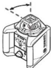
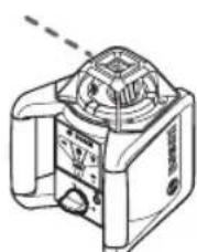
To position the laser line or the laser point within the rotational plane, manually turn the rotation head 10 to the requested position or use the remote control 20.
Turning the Rotational Plane when in the Vertical Position
When the laser tool is in the vertical position, it is possible to rotate the laser point, laser line or rotational plane around the vertical axis with help of the remote control 20. For this, follow the operating instructions of the remote control.
Leveling Accuracy
Automatic leveling
Overview
After switching on, the laser tool automatically detects the horizontal or vertical position. To change between horizontal and vertical position, switch the laser tool off, reposition it and switch on again.
After switching on, the laser tool checks the horizontal and vertical position and automatically levels out any unevenness within the self-leveling range of approx. 8% (5^)
When the laser tool is inclined by more than 8% after switching on or after a position change, leveling in is no longer possible. In this case, the rotor is stopped, the laser flashes and leveling indicator 3 continuously lights up red. Reposition the laser tool and wait for it to re-level. Without repositioning, the laser is automatically switched off after 2 minutes and the laser tool after 2 hours.
When the laser tool is leveled in, it continuously checks the horizontal and vertical position. Automatic re-leveling takes place after position changes. To avoid faulty measurements, the rotor stops during the leveling process, the laser flashes and the leveling indicator 3 flashes green.
Shock-warning Function
The laser tool has a shock-warning function; after position changes or shock to the laser tool, or in case of ground vibrations, it keeps the laser tool from leveling in at changed heights, and thus prevents errors.
To switch on the shock-warning function, press the shock-warning button 2. The shock-warning indicator 1 continuously lights up green, and the shock-warning function is activated after 30 seconds.
When the leveling-accuracy range is exceeded after a position change of the laser tool or when heavy ground vibrations are detected, the shock-warning function is actuated: The rotation stops, the laser flashes, the leveling indicator 3 goes out and the shock-warning indicator 1 flashes red. The current operating mode is stored.
After the shock-warning function is actuated, press the shock-warning button 2. The shock-warning function is restarted and the laser tool starts leveling. As soon as the laser tool is leveled in (leveling indicator 3 continuously lights up green), it starts in the stored operating mode. Now, check the position of the laser beam with a reference point and adjust it, if required.
If operation is not restarted by pressing button 2 after the shock warning function has actuated, the laser is automatically switched off after 2 minutes and the laser tool after 2 hours.
To switch off the shock-warning function, press shock-warning button 2 once, or, when the shock warning is actuated (shock-warning indicator 1 flashing red) press it twice. When the shock-warning function is shut off, the shock warning indicator 1 goes out.
Accuracy Check
Influences on Accuracy
The ambient temperature has the greatest influence. Especially temperature differences occurring from the ground upward can divert the laser beam.
In addition to external influences, device specific influences (e.g. falls or heavy impacts) can also lead to deviations. For this reason, check the accuracy each time before beginning work.
The deviations play a role in excess of approx. 65 ft (20 m) distance and can easily reach two to four times the deviation at 330 ft (100 m).
Because the largest difference in temperature layers is close to the ground, the laser tool should always be mounted on a tripod when operating at distances exceeding 65 ft (20 m). If possible, also set up the laser tool in the center of the work area.
If the laser tool exceeds the maximum deviation in one of the four measuring procedures, have it checked by a Bosch customer service center.
WARNING It is the user's responsibility to periodically check the accuracy of the laser tool as work progresses. Always check the accuracy of the laser tool after it has been dropped or subjected to extreme temperatures and temperature variations.
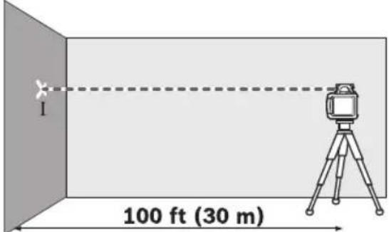
Checking the Leveling Accuracy in the Horizontal Position
An unobstructed area of 100 ft (30m) on a firm surface in front of a wall is required for the check. A complete accuracy check must be carried out for the X- and Y-axis.
- Mount the laser tool in the horizontal position onto a tripod or place it on a firm and level surface at a distance of 100 ft (30 m) to the wall. Switch the laser tool on.
After the leveling, mark the center of the laser beam on the wall (point I).
- Rotate the laser tool by 180^ , allow it to level in and mark the center point of the laser beam on the wall (point II). Make sure that point II is as vertical as possible above or below point I.
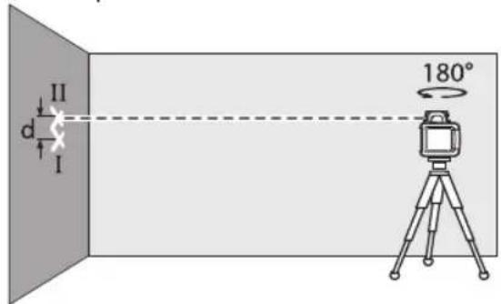
- The difference d of both marked points I and II on the wall results in the actual height deviation of the laser tool for the measured axis.
Repeat the procedure for the other axis. For this, turn the laser tool by 90^ before starting.
The maximum permitted deviation over the recommended distance of 100 ft (30m) is as follows:
For GRL800-20HV:
$$ 1 0 0 \mathrm {f t} \times \pm 3 / 1 6 \text {i n} = \pm 3 / 1 6 \text {i n} $$
$$ (3 0 \mathrm {m} \times \pm 0. 1 5 \mathrm {m m} = \pm 4. 5 \mathrm {m m}) $$
For GRL900-20HV and GRL1000-20HV:
$$ 1 0 0 f t x \pm 1 / 8 i n = \pm 1 / 8 i n $$
$$ (3 0 \mathrm {m} \times \pm 0. 1 0 \mathrm {m m} = \pm 3. 0 \mathrm {m m}) $$
The difference d between points I and II must therefore be maximum 3/8 in (9mm) for GRL800-20HV and 14 in (6 mm) for GRL900-20HV and GRL1000-20HV in each of the two accuracy check procedures.
Checking the Leveling Accuracy in the Vertical Position
An unobstructed area of 30 ft (10 m) on a firm surface in front of a wall is required for the check. Fasten a plumb bob rope to the wall.
Mount the laser tool in the vertical position onto a tripod, or place it on a firm and level surface. Switch the laser tool on and allow it to level.
Align the laser tool such that the laser beam impinges centrally on the plumb bob rope at the upper end. The difference d between laser beam and plumb bob rope at the bottom end of the rope results in the deviation of the laser tool to the vertical line.
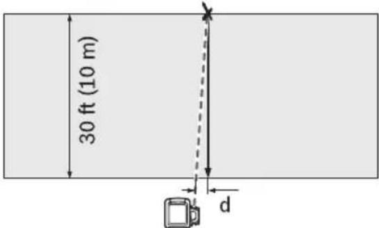
The maximum permitted deviation over a 30 ft (10 m) distance is as follows:
For GRL800-20HV:
$$ \begin{array}{l} 3 0 \mathrm {f t} \times \pm 3 / 1 6 \text {i n} = \pm 1 / 1 6 \text {i n} \ (1 0 \mathrm {m} \times \pm 0. 1 5 \mathrm {m m} = \pm 1. 5 \mathrm {m m}) \ \end{array} $$
For GRL900-20HV and GRL1000-20HV:
$$ \begin{array}{l} 3 0 f t x \pm 1 / 8 i n = \pm 3 / 6 4 i n \ (1 0 \mathrm {m} \times \pm 0. 1 \mathrm {m m} = \pm 1 \mathrm {m m}) \ \end{array} $$
The difference d must therefore be a maximum of 1/16 in (1.5 mm) for GRL800-20HV and 3/64 in (1 mm) for GRL900-20HV and GRL1000-20HV.
Applications
Indicating a Plumb Line/Vertical Plane (see figure B)
To indicate a plumb line or a vertical plane, set up the laser tool in the vertical position.
When the vertical plane is supposed to run at a right angle to a reference line (e.g. a wall), then align the plumb beam 9 with this reference line.
The plumb line is indicated by the variable laser beam 6.
Working without Laser Receiver (see figure C)
Under favorable light conditions (dark environment) and for short distances, it is possible to work without the laser receiver. For better visibility of the laser beam, either select line operation, or select point operation and manually (or by using the remote control 20) rotate the rotation head 10 to the target location.
Working with the Laser Receiver (see figure D)
Under unfavorable light conditions (bright environment, direct sunlight) and for larger distances, use the laser receiver for improved finding of the laser beam. When working with the laser receiver, select rotational operation with the highest rotational speed.
Operating Over Long Distances (see figure E)
When operating over long distances, the laser receiver must be used to find the laser beam. In order to reduce interferences, the laser tool should always be set up in the center of the work area and on a tripod.
Working Outdoors (see figure F)
The laser receiver should always be used when working outdoors.
When working on unstable ground, mount the laser tool onto the tripod 21. Activate the shock-warning function in order to avoid errors in case of ground vibrations or shock to the laser tool.
| Laser beam | Rotation of the laser* | green red green red | |||
| Switching on the laser tool(1 s self-check) | ● | ● | |||
| Leveling in or re-leveling | 2x/s | ○ | 2 | x/s | |
| Laser tool leveled in/ready for operation | ● | ● | ● | ||
| Self-leveling range exceeded | 2x/s | ○ | ● | ||
| Shock-warning function activated | ● | ||||
| Shock warning actuated | 2x/s | ○ | 2x/s | ||
| Battery voltage for ≤2 h operation | 2x/s | ||||
| Battery empty | ○ | ○ | ● | ||
- f or line and rotational operation
2x/s Flashing frequency (twice per second)
Continuous operation
Function stopped
Use with Accessories
Laser Viewing Glasses (Accessory)
WARNING DO NOT use the laser viewing glasses as
safety goggles. The laser viewing glasses are used for improved visualization of the laser beam, but they do not protect against laser radiation.
DO NOT use the laser viewing glasses as sun glasses or in traffic. The laser viewing glasses do not afford complete UV protection and reduce color perception.
The laser viewing glasses filter out the ambient light. This makes the red light of the laser appear brighter for the eyes.
Working with the Laser Receiver (Accessory)
WARNING Have your laser receiver serviced by a qualified repair person using only identical replacement parts. This will ensure that the safety of the laser receiver is maintained.
Read and strictly observe the safety warnings in the operating instructions of the laser receiver.
Under unfavorable light conditions (bright environment, direct sunlight) and for larger distances, use the laser receiver 23 and 13 for improved finding of the laser beam.
When working with the laser receiver, select rotational operation with the highest rotational speed.
Before working with the laser receiver, read and observe the laser receiver operating instructions.
Working with the Remote Control (Accessory)
While pressing the operator buttons, the laser tool can be brought out of alignment so that the rotation is briefly stopped. This effect is avoided when using the remote control 20.
Reception lenses 7 for the remote control are located on three sides of the laser tool (GRL800-20HV has a single reception lens located on the front of the laser tool), among other locations above the control panel on the front side.
Working with the Tripod (Accessory)
The laser tool is equipped with a 5/8 tripod mount for horizontal operation on a tripod.
Place the laser tool via the tripod mount 16 onto the 5 / 8 male thread of the tripod and screw the locking screw of the tripod tight.
On a tripod with a measuring scale on the elevator column, the height difference can be adjusted directly.
Working with Wall Mount/Alignment Unit (Accessory) (see figure A)
You can also mount the laser tool to the wall mount with alignment unit 25. For this, screw the 5 / 8 screw 28 of the wall mount into the tripod mount 16 of the laser tool.
Mounting to a wall: Mounting to a wall is recommended, e.g., for work above the elevation height of tripods or for work on unstable surfaces and without tripod. For this, fasten the wall mount 25, with the laser tool mounted, as vertical as possible to a wall.
For mounting to the wall, you can either fasten the wall mount 25 with fastening screw 26 to a lath (width maximal 8mm ) or hang it up with two hooks.
Mounting on a tripod: The wall mount 25 (WM4 only) can also be screwed onto a tripod with the tripod mount on the back side. This method of fastening is especially recommended for work where the rotational plane is to be aligned with a reference line.
With the alignment unit, the mounted laser tool can be moved vertically (when mounted to the wall) or horizontally (when mounted to a tripod) within a range of approx. 6 in. For this, loosen screw 27 on the alignment unit, move the laser tool to the desired position, and retighten screw 27 again.
Working with the Ceiling Measurement Plate (see figure A)
As an example, the ceiling measurement plate 29 can be used for easy height adjustment of drop ceilings. Fasten the ceiling measurement plate with the magnetic holder, e.g., to a beam.
The reflecting half of the ceiling measurement plate improves the visibility of the laser beam in unfavorable conditions; the laser beam can also be seen from the rear side through the transparent half.
Working with the Measuring Rod (Accessory) (see figure F)
WARNING Do not operate during storms or near high voltage. Risk of being struck by lightning or electrocution.
Keep at a safe distance from electrical installations. It is essential to work in this environment, first contact the safety authorities responsible for the electrical installations and follow their instructions.
For checking irregularities or projecting gradients, it is recommended to use the measuring rod 22 together with the laser receiver.
Maintenance and Service
WARNING
Store and transport the tool only in the supplied
protective case.
Check the tool each time before using.
Keep the tool clean and dry at all times to ensure proper and safe operation.
Do not immerse the tool into water or other fluids.
Wipe off debris using a moist and soft cloth. Do not use any cleaning agents or solvents.
Regularly clean the surfaces at the exit opening of the laser.
In case of visible damage or loose components in the interior of the tool, the safe function is no longer ensured.
If the tool should fail despite the care taken in manufacturing and testing
procedures, repair should be carried out by an authorized after-sales service center for Bosch power tools.
In all correspondence and spare parts orders, please always include the 10-digit article number given on the type plate of the tool.
In case of repairs, send in the tool packed in its protective case 30.
ENVIRONMENT PROTECTION
Recycle raw materials & batteries instead of disposing of waste. The unit, accessories, packaging & used batteries should be sorted for
environmentally friendly recycling in accordance with the latest regulations.
LR30

LR30 General Safety Rules

WARNING
Read all instructions.
Failure to follow all instructions listed below may result in
hazardous radiation exposure, electric shock, fire and/or serious injury.

Keep the laser receiver away from cardiac pacemakers. The magnet plate 5a generates a field that can impair the function of cardiac pacemakers.
original spare parts. This ensures that the safety of the laser receiver is maintained.
- Do not operate the laser receiver explosive environments, such as in the presence of flammable liquids, gases or dusts. Sparks can be created in the laser receiver which may ignite the dust or fumes.
-
Read and strictly observe the safety warnings in the operating instructions of the rotational laser.
-
Keep the laser receiver from magnetic data medium magnetically sensitive equipment. The effect of the magnet plate 5a can lead to irreversible data loss.
away Noise Information
A-weighted sound pressure level of the audio signal at one meter distance is 80 dB(A).
- Have the laser receiver repaired only through qualified specialists using
LR30 Intended Use
The laser receiver is intended for swift finding of rotating laser beams in the wavelength listed in the "Technical Data".
The laser receiver is suitable for indoor and outdoor use.
LR30 Preparation
Inserting/Replacing the Battery
Alkaline batteries are recommended for the laser receiver.
Pull the latch 11a of battery lid outward and open the battery lid 13a.
When inserting batteries, pay attention to the correct polarity.
In the case of a dead battery, the laser receiver will beep and flash the LEDs then automatically shut down when battery has been exhausted.
△WARNING
Remove the batteries from the laser receiver
when not using it for extended periods. When storing for extended periods, the batteries can corrode and self-discharge.
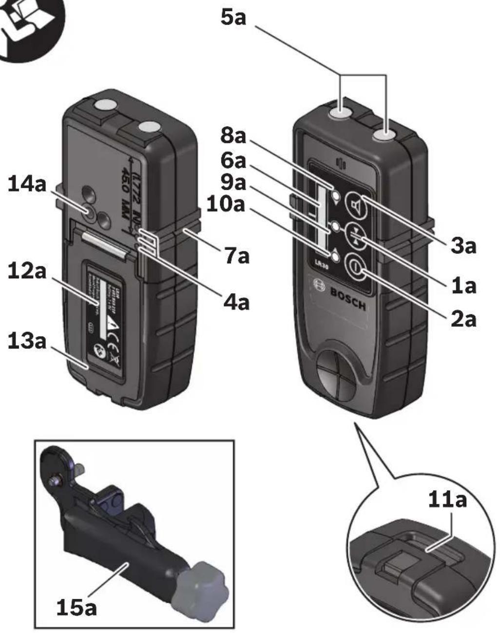
LR30 Features
The numbering of the product features shown refers to the illustration of the laser receiver on the graphic page 20.
1a Button for selecting the accuracy
9a Center-indication LED
2a On/Off button
10a Direction LED "move upward"
3a Audio signal button
11a Latch of battery lid
4a Back LEDs
12a Serial number
5a Magnetic mounts
13a Battery lid
6a Reception area for the laser beam
14a Mounting hole for M6 thread
7a Center mark
15a Mounting bracket
8a Direction LED "move downward"
LR30 Technical Data
Laser Receiver LR30
Article number 3601K69211
Receivable wavelength 635-650 nm
Suitable for rotational laser level GRL800-20HV
Working range 1) 500 ft (150 m)
Receiving angle 45^
Receiving rotation speed 150,300,600 min
Accuracy 2)3)4
-Setting "fine" ±1/16 in (±1.5 mm)
-Setting "coarse" ±1/8 in (±3 mm)
Operating temperature 14^ 122^ (-10^ +50^)
Storage temperature -4^ 158^ (-20^ +70^)
Battery 1 x 9V 6LR61
Operating time, approx. 30h
Weight according to EPTA-Procedure 01:2014 .75 lb (0.34kg)
Dimensions 2.25'' × 1'' × 5'' (57x29x131 mm)
1) The working range (radius) can be reduced due to unfavorable ambient conditions (e.g. direct sunlight).
2) Depends on clearance between laser receiver and rotational laser level.
3) Dependent on laser class and laser type of the rotational laser level.
4) The accuracy can be impacted by unfavorable environmental conditions (e.g. direct sun irradiation).
The laser receiver can be clearly identified with the serial number 12a on the type plate.
LR30 Operation
Initial Operation
- Protect the laser receiver against moisture.
- Do not subject the laser receiver to extreme temperatures or variations in temperature.
As an example, do not leave it in vehicles for longer periods. In case of large variations in temperature, allow the laser receiver to adjust to the ambient temperature before putting it into operation. In case of extreme temperatures or variations in temperature, the accuracy of the laser receiver can be impaired.
WARNING
DO NOT stare directly at the laser beam or project
the laser beam directly into the eyes of others. Serious eye injury could result.
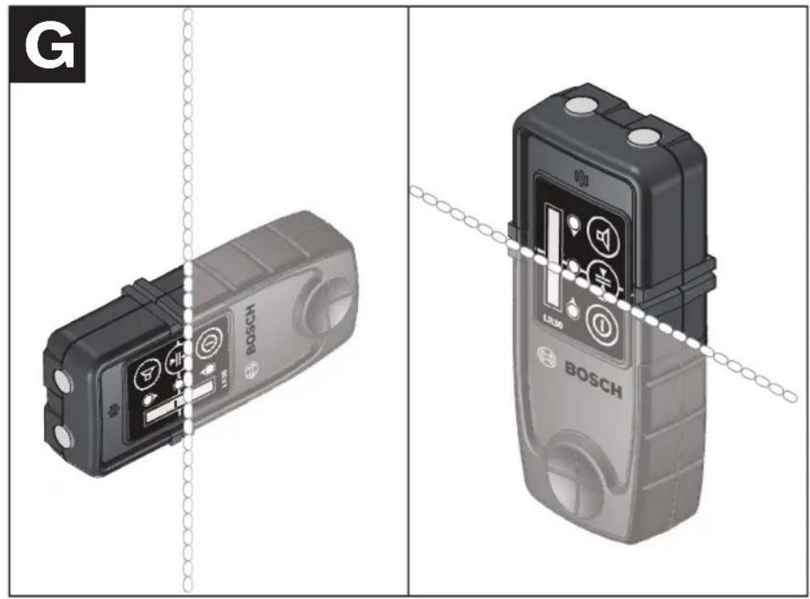
Setting Up the Laser Receiver (see figure G)
Position the laser receiver at least 3ft (1m) away from the laser tool. Switch on the laser tool, and select horizontal or vertical operation.
Position the laser receiver in such a manner that the laser beam can reach the reception area 6a. Align the laser receiver in such a manner that the laser beam runs horizontally through the reception area (as shown in the figure).
Switching On and Off
- A loud audio signal sounds when switching on the laser receiver. Therefore, keep the laser receiver away from your ear or other people when switching on. The loud audio signal can cause hearing defects.
To switch the laser receiver on, press the On/ Off button 2a. All LEDs light up briefly and an audio signal sounds.
To switch the laser receiver off, press the On/ Off button 2a again. Before switching off, all LEDs briefly light up.
When no button is pressed on the laser receiver for approx. 6 minutes and when no laser beam reaches the reception area 6a for 6 minutes, the laser receiver automatically switches off in order to save the battery. The switching off is indicated by brief lighting up of all LEDs.
Selecting the Setting of the Center Indicator
With button 1a, you can specify with which accuracy the position of the laser beam is indicated on the reception area:
- "Fine" adjustment
- "Coarse" adjustment
Whenever switching on the laser receiver the accuracy level "Fine" is set.
Direction Indicators
The position of the laser beam on the reception area 6a is indicated:
- via the LEDs "move downward" 8a, "move upward" 10a or the center-indication LED 9a, or corresponding LED 4a on the back of the tool,
- optionally via the audio signal (see "Audio Signal for Indication of the Laser Beam").
Tool too low: When the laser beam runs through the top half of the reception area 6a, the corresponding direction LED 10a lights up. When the audio signal is switched on, a low frequency signal sounds. Move the tool upward in the direction of the arrow.
Tool too high: When the laser beam runs through the bottom half of the reception area 6a, the corresponding direction LED 8a lights up. When the audio signal is switched on, a high frequency signal sounds. Move the tool downward in the direction of the arrow.
Tool in center position: When the laser beam runs through the reception area 6a at the center mark 7a, the corresponding center-indication LED 9a lights up. When the audio signal is switched on, a continuous signal sounds.
Audio Signal for Indication of the Laser Beam
The position of the laser beam on the reception area 6a can be indicated via an audio signal.
After the laser receiver has been switched on, the volume level can be switched off.
To switch off the audio signal, push the audio signal button 3a.
Working Advice
Marking
When the laser beam runs through the center of the reception area 6a, its height can be marked at the center mark 7a right and left on the tool.
When marking, make sure to align the tool for each laser beam, both vertically and horizontally. If this is not done, then the marks will be offset from the laser beam.
Attaching with the Magnet (see figure H)
When a mounting bracket is not required, the tool can be attached to steel parts via the top side using the magnet mounts 5a.
LR30 Maintenance and Service
Keep the laser receiver clean at all times.
Do not immerse the laser receiver into water or other fluids.
Wipe off debris using a moist and soft cloth. Do not use any cleaning agents or solvents.
If the laser receiver should fail despite the care taken in manufacturing and testing procedures, repair should be carried out by an authorized after-sales service center for Bosch power tools.
In all correspondence and spare parts orders, please always include the 10-digit article number given on the type plate of the laser receiver.
ENVIRONMENT PROTECTION

Recycle raw materials & batteries instead of disposing of waste. The unit, accessories, packaging & used batteries should be sorted for environmentally
friendly recycling in accordance with the latest regulations.
LR10

LR10 General Safety Rules

WARNING
Read all instructions.
Failure to follow all instructions listed below may result in
hazardous radiation exposure, electric shock, fire and/or serious injury.

Keep the laser receiver away from cardiac pacemakers. The magnet plate 7b generates a field that can impair the function of cardiac pacemakers.
- Do not operate the laser receiver in explosive environments, such as in the presence of flammable liquids, gases or dusts. Sparks can be created in the laser receiver which may ignite the dust or fumes.
- Read and strictly observe the safety warnings in the operating instructions of the rotational laser.
Noise Information
The A-weighted sound pressure level of the audio signal at one meter distance is 80 dB(A).

Do not hold the tool close to your ear.
- Keep the laser receiver from magnetic data medium magnetically sensitive equipment. The effect of the magnet plate 7b can lead to irreversible data loss.
- Have the laser receiver repaired only through qualified specialists using original spare parts. This ensures that the safety of the laser receiver is maintained.
LR10 Intended Use
The laser receiver is intended for swift finding of rotating laser beams in the wavelength listed in the "Technical Data".
The laser receiver is suitable for indoor and outdoor use.
LR10 Preparation
Inserting/Replacing the Battery
Alkaline batteries are recommended for the laser receiver.
Pull the latch 16b of battery lid outward and open the battery lid 15b.
When inserting batteries, pay attention to the correct polarity according to the representation on the inside of the battery compartment.
When the battery low indicator 22b appears for the first time on the display 6b, the laser receiver can still be operated for approx. 2h

Remove the batteries from the laser receiver
when not using it for extended periods.
When storing for extended periods, the batteries can corrode and self-discharge.
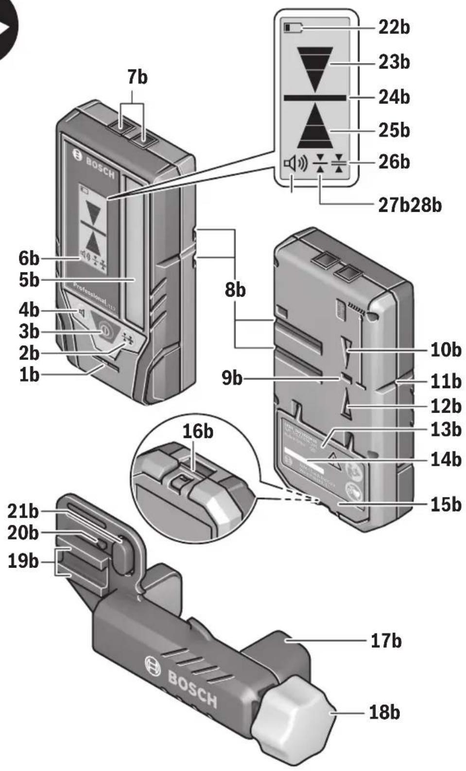
LR10 Features
The numbering of the product features shown refers to the illustration of the measuring tool on the graphic page 26.
1b Speaker
16b Latch of battery lid
2b Button for selecting the accuracy
17b Mounting bracket (1608 M00 C1L)
3b On/Off button
18b Rotary knob of the mounting bracket
4b Audio signal button
19b Guide rail
5b Reception area for the laser beam
20b Holder latch
6b Display
21b Push-button to release the lock
7b Magnets
8b Guide groove for holder
9b Center-indication LED (rear)
10b Direction LED "move downward"
11b Center mark
12b Direction LED "move upward"
13b Type plate
14b Serial number
15b Battery lid
Display Elements
22b Battery low indicator
23b Direction indicator "move downward"
24b Centre indicator
25b Direction indicator "move upward"
26b Indicator for "Coarse" accuracy
27b Indicator for "Fine" accuracy
28b Audio signal indicator
LR10 Technical Data
Laser Receiver LR10
| Article number 3601K69N10 | |
| Receivable wavelength 635-650 nm | |
| Suitable for rotational laser level GRL 900-20HV, GRL1000-20HV | |
| Working range1) | 500 ft (150 m) |
| Receiving angle 45° | |
| Receiving rotation speed 150,300,600 min | -1 |
| Accuracy2) 3) 4) | |
| -Setting “fine” | ±1/32 in (±1 mm) |
| -Setting “coarse” | ±1/8 in (±3 mm) |
| Operating temperature 14°F ~ 122°F (-10°C ~ +50°C) | |
| Storage temperature -4°F ~ 158°F (-20°C ~ +70°C) | |
| Battery 2 x 1.5V LR6 (AA) | |
| Operating time, approx. 40h | 5) |
| Weight according to EPTA-Procedure 01:2014 | .33 lb (0.15kg) |
| Dimensions | 2.9" x 1.1" x 5.4" (73x28x137 mm) |
| Degree of protection | IP 54 (dust and splash water protected) |
1) The working range (radius) can be reduced due to unfavorable ambient conditions (e.g. direct sunlight).
2) depends on clearance between laser receiver and rotational laser level
3) dependent on laser class and laser type of the rotational laser level
4) The accuracy can be impacted by unfavorable environmental conditions (e.g. direct sun irradiation).
5) With display illumination deactivated.
The laser receiver can be clearly identified with the serial number 14b on the type plate.
LR10 Operation
Initial Operation
- Protect the laser receiver against moisture and direct sunlight.
- Do not subject the laser receiver to extreme temperatures or variations in temperature. As an example do not leave it in vehicles for a long time. In case of large variations in temperature, allow the laser receiver to adjust to the ambient temperature before putting it into operation. In case of extreme temperatures or variations in temperature, the accuracy of the laser receiver can be impaired.
Setting up the Laser receiver (see figure 1)
Position the laser receiver at least 20 inches away from the rotational laser.
Position the laser receiver in such a manner that the laser beam can reach the reception area 5b. Align the laser receiver in such a manner that the laser beam runs laterally through the reception area (as shown on the figure).
Switching On and Off
- A loud audio signal sounds when switching on the tool. Therefore, keep the tool away from your ear or other people when switching on. The loud audio signal can cause hearing defects.
To switch the laser receiver On, press the On/ Off button 3b. All display indicators as well as all LEDs light up briefly and an audio signal sounds.
Every time when the laser receiver is switched on, both volume and accuracy settings are stored from the last setting before the receiver was switched off.
To switch the laser receiver Off, press the On/Off button 3b again. All LEDs and all display indicators light up briefly before the receiver switches off, and an audio signal sounds.
If no buttons on the laser receiver are pressed and no laser beam reaches the reception area 5b, for approx. 10 mins, the laser receiver switches off automatically to save energy. The switching off is indicated by all LEDs and all display indicators lighting up briefly, and an audio signal sounding.
Selecting the Accuracy setting
With button 2b, you can specify with which accuracy the position of the laser beam is indicated on the reception area:
- "Fine" adjustment (indication 27b on the display),
- "Coarse" adjustment (indication 26b on the display).
Every time when the laser receiver is switched on, the accuracy setting is stored from before the receiver was switched off.
Direction Indicators
The position of the laser beam on the reception area 5b is indicated:
by the direction indicators "move downward" 23b, "move upward" 25b or center 24b on the display 6b on the front of the laser receiver,
- by the LEDs "move downward" 10b, "move upward" 12b or center 9b on the back of the laser receiver,
- optionally by the audio signal (see "Audio Signal for Indication of the Laser Beam")
Laser receiver too low: If the laser beam runs through the upper half of the reception area 5b, the direction indicator 25b on the display and the corresponding LED 12b light up. If the audio signal is switched on, a signal sounds at high frequency. Move the laser receiver upward in the arrow direction.
Laser receiver too high: If the laser beam runs through the lower half of the reception area 5b, the direction indicator 23b on the display and the corresponding LED 10b light up. If the audio signal is switched on, a signal sounds at low frequency. Move the laser receiver downward in the arrow direction.
Laser receiver in center position: When the laser beam runs through the reception area 5b at the center mark 11b, the center indicator 24b on the display and the corresponding center-indicator LED 9b light up. When the audio signal is switched on, a continuous signal sounds.
Audio Signal for Indication of the Laser Beam
The position of the laser beam on the reception area 5b can be indicated via an audio signal.
The volume level can be increased or switched off.
To change the volume level or switch the audio signal off, push the acoustic signal button 4b until the desired volume level is indicated on the display. At low volume level, the audio signal indicator 28b appears on the display with one bar; at high volume level, the indicator appears with three bars. When the audio signal is set to off, the indicator goes out. Independent of the audio signal setting, a short beep sounds at low volume level each time a button is pressed on the laser receiver.
Every time when the laser receiver is switched on, the volume setting is stored from before the receiver was switched off.
Backlight
The back light of the display is switched on at full strength when the laser receiver is switched on. If no laser beam is detected and
no buttons are pressed for 1 minute, the back light switches off automatically.
The backlight also switches off automatically if there is continuous laser detection and no buttons are pressed for 2 minutes. The back light can be switched off manually by pressing the accuracy setting button 2b and the audio signal button 4b simultaneously
Working Advice
Marking
When the laser beam runs through the center of the reception area 5b, its height can be marked at the center mark 11b right and left of the laser receiver.
When marking, make sure to align the laser receiver both vertically and horizontally. If this is not done the laser marks will be offset from the laser beam.
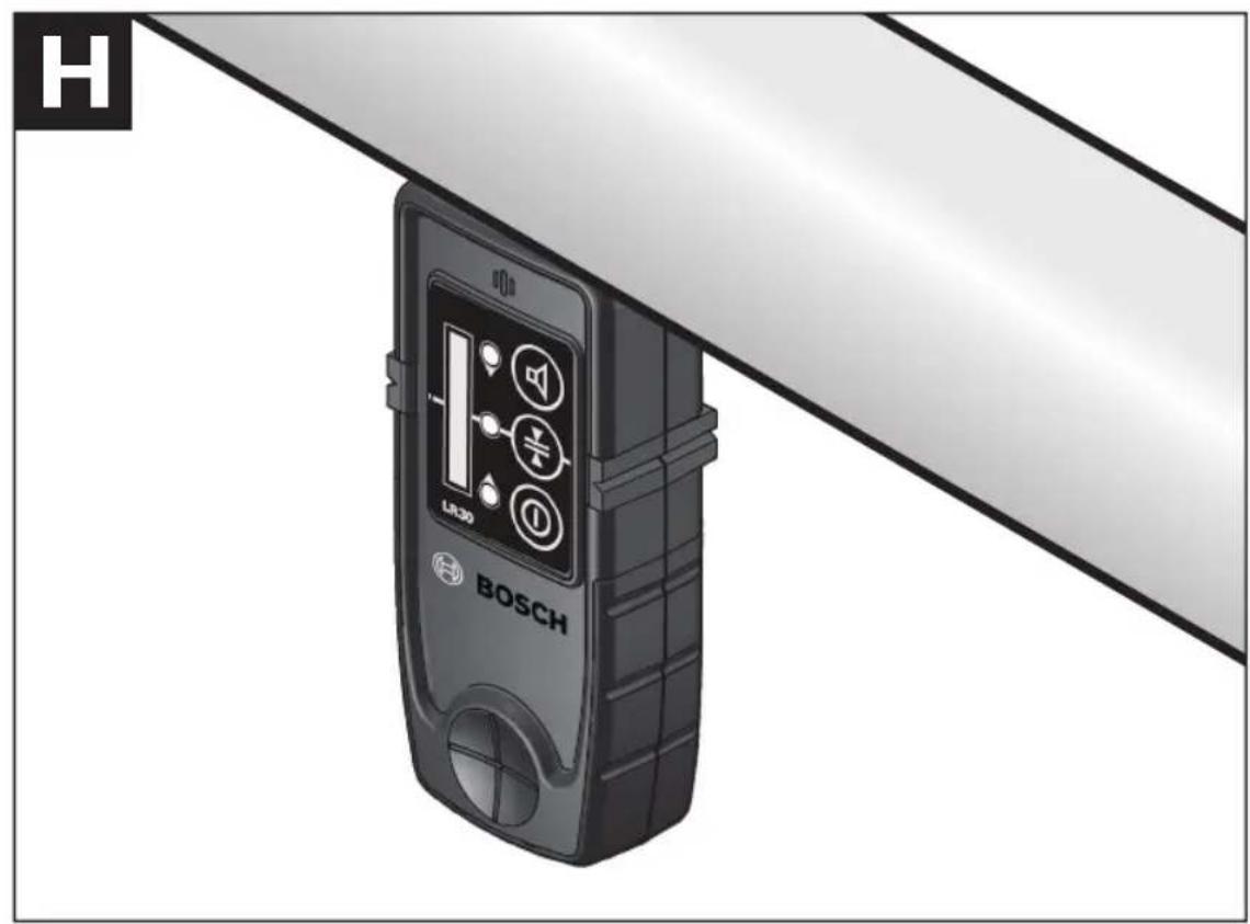
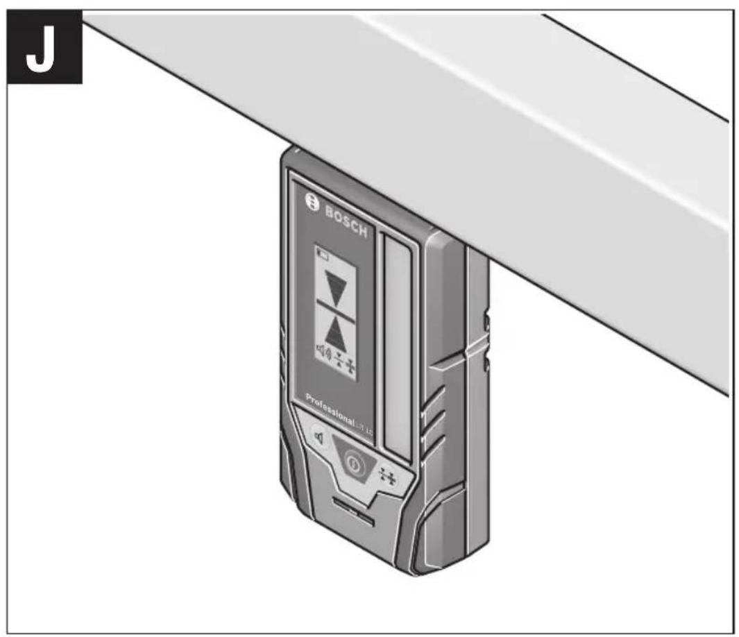
Attaching with the Magnet (see figure J)
When a positive-lock attachment is not absolutely required, the magnets 7b on top of the laser receiver can be used to attach the receiver to steel parts.
LR10 Maintenance and Service
Keep the laser receiver clean at all times.
Do not immerse the laser receiver into water or other fluids.
Wipe off debris using a moist and soft cloth. Do not use any cleaning agents or solvents.
If the laser receiver should fail despite the care taken in manufacturing and testing procedures, repair should be carried out by an authorized after-sales service center for Bosch power tools.
In all correspondence and spare parts orders, please always include the 10-digit article number given on the type plate of the tool.
ENVIRONMENT PROTECTION
Recycle raw materials & batteries instead of disposing of waste. The unit, accessories, packaging & used batteries should be sorted for environmentally
friendly recycling in accordance with the latest regulations.
RC1 Remote Control
(Optional accessory for the GRL800-20HV)
RC1 General Safety Rules
WARNING
Read all instructions.
Failure to follow all
instructions listed below may result in hazardous radiation exposure, electric shock, fire and/or serious injury.
-
Have the remote control repaired only through a qualified repair person and only using identical replacement parts. This will ensure that the functionality of the remote control is maintained.
-
Do not operate the remote control in explosive atmospheres, such as in the presence of flammable liquids, gases or dusts. Sparks can be created in the remote control which may ignite the dust or fumes.
- Read and strictly observe the safety warnings in the operating instructions of the rotational laser.
RC1 Intended Use
The remote control is intended for controlling rotational laser levels in indoor and outdoor use.
RC1 Preparation
Inserting/Replacing the Battery
Using alkali-manganese batteries is recommended for operation of the remote control.
To open the battery lid 8c, press the latch 9c in the direction of the arrow and remove the battery lid. Insert the battery provided.
When inserting, pay attention to the correct polarity according to the representation on the inside of the battery compartment.
△WARNING
Remove the battery from the remote control
when not using it for longer periods.
When storing for longer periods, the battery can corrode and self-discharge.
RC1 Technical Data
Remote control RC1
| Working range1) | 100 ft (30 m) |
| Operating temperature | 14 °F ~ 122 °F (-10 °C) |
| Storage temperature | -4 °F ~ 158 °F (-20 °C ~ +70 °C) |
| Battery | 1 x 1.5 V LR06 (AA) |
| Weight according to EPTA-Procedure 01/2003 | 2.4 oz. (69 g) |
1) The working range can be decreased by unfavorable environmental conditions (e.g. direct sun irradiation).
Please observe the article number on the type plate of your remote control.
The trade names of individual remote controls may vary.
For clear identification of your remote control, see the serial number 10c on the type plate.
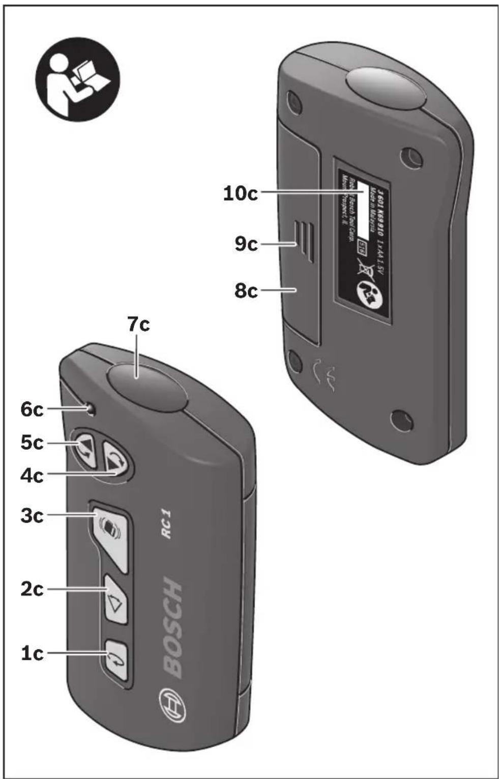
RC1 Features
The numbering of the product features refers to the illustrations on the remote control graphics page 32.
1c Button for rotational operation and selection of the rotation speed
5c Button for "rotation in counterclockwise direction"
2c Button for line operation and line length selection
6c Operation indicator
3c Shock-warning reset button
7c Outlet opening for infra-red beam
4c Button for "rotation in clockwise direction"
8c Battery lid
9c Latch of battery lid
10c Serial number
RC1 Operation
Initial Operation
- Protect the remote control moisture and direct sunlight.
- Do not subject the remote control to extreme temperatures or variations in temperature. As an example, do not leave it in vehicles for longer periods. In case of large variations in temperature, allow the remote control to adjust to the ambient temperature before putting it into operation.
The remote control remains ready for operation as long as a battery with sufficient voltage is inserted.
Set up the laser tool in such a manner that the signals of the remote control directly reach one of the reception lenses on the laser tool (for this, see the operating instructions of the laser tool). When the remote control cannot be pointed directly against a reception lens, the working range is reduced. By reflecting the signal (e.g. against walls), the working range can be improved, even for indirect signals.
After pressing a button on the remote control, the illuminated operation indicator 6c indicates that a signal was sent out.
Switching the laser tool on/off with the remote control is not possible.
RC1 Operating Modes
For detailed information of the laser tool functions, see the operating instructions of the laser tool.

Rotational Operation (150/300/600 min-1)
The function of the button for rotational operation 1c on the remote control is identical with that on the laser tool.
Each time after switching on, the laser tool is in rotational operation mode with average rotational speed.
To switch from line operation to rotational operation, press the rotational operation button 1c. Rotational operation starts with average rotational speed.
To change the rotational speed, press the rotational operation button 1c again until the requested speed is reached.

Line Operation, Point Operation (10^ / 25^ / 50^,0^)
The function of the button for line operation 2c on the remote control is identical with that on the laser tool.
To switch to line or point operation, press the line operation button 2c. The laser tool switches to line operation with the smallest aperture angle.
To change the aperture angle, press the line operation button 2c. The aperture angle is increased in two steps; at the same time, the rotational speed is increased with each step. When pressing the line operation button 2c a third time, the laser tool switches to point operation after brief post-pulsation. Pressing button 2c again takes you back to line operation with the smallest aperture angle.
Note: Due to inertia, it is possible for the laser to slightly move beyond the end point of the laser line.

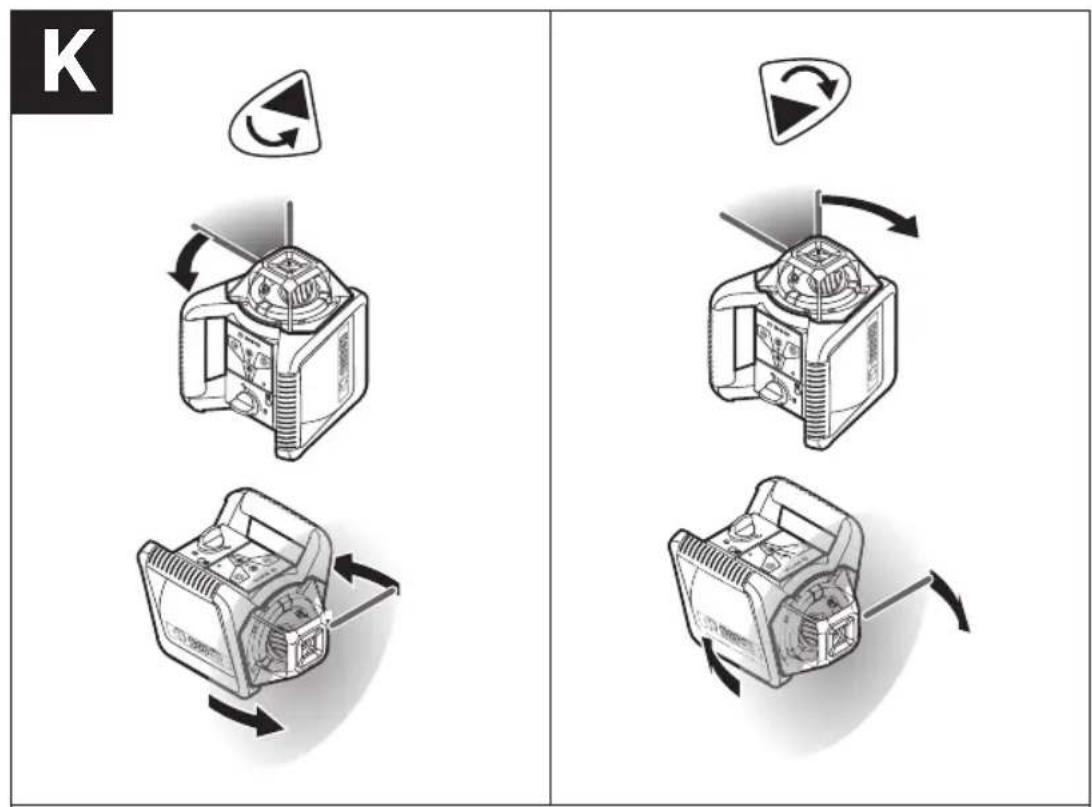
Rotating the Laser Line/ Laser Dot or the Rotational Plane (see figure K)
Rotating the laser line/laser dot or the rotational plane is possible only with the remote control.
When the laser tool is in the horizontal position, the laser line (in line operation) or the laser dot (in point operation) can be positioned within the rotational plane of the laser.
Press button 4c to rotate in clockwise direction, and button 5c to rotate in counterclockwise direction. In rotational operation, pressing the buttons has no effect.
When the rotational laser is in the vertical position, it is possible to rotate the laser point, laser line or rotational plane around the vertical axis. Rotating is possible only within the self-leveling range 5^ toward the left or right).
Press button 4c to rotate in clockwise direction, and button 5c to rotate in counterclockwise direction.

Reset Shock-warning Function
The laser level has a shock warning function; after position changes or shock to the laser tool, or in case of ground vibrations, it keeps the laser tool from leveling in at changed heights, and thus prevents vertical errors.
Switching the shock-warning function on and off is possible only on the laser tool. Once the shock-warning function has actuated, is can be restarted via the remote control.
After actuation of the shock warning function, the rotation of the laser is stopped, the laser flashes, the leveling indicator goes out, and the shock warning indicator flashes red. The current operating mode is stored.
After the shock-warning function has actuated, press the shock warning reset button 3c. The shock-warning function is restarted and the rotational laser starts leveling. As soon as the laser tool is levelled in (the leveling indicator on the laser tool continuously lights up green), it starts in the stored operating mode. Now, check the height of the laser beam with a reference point and correct the height, if required.
RC1 Applications
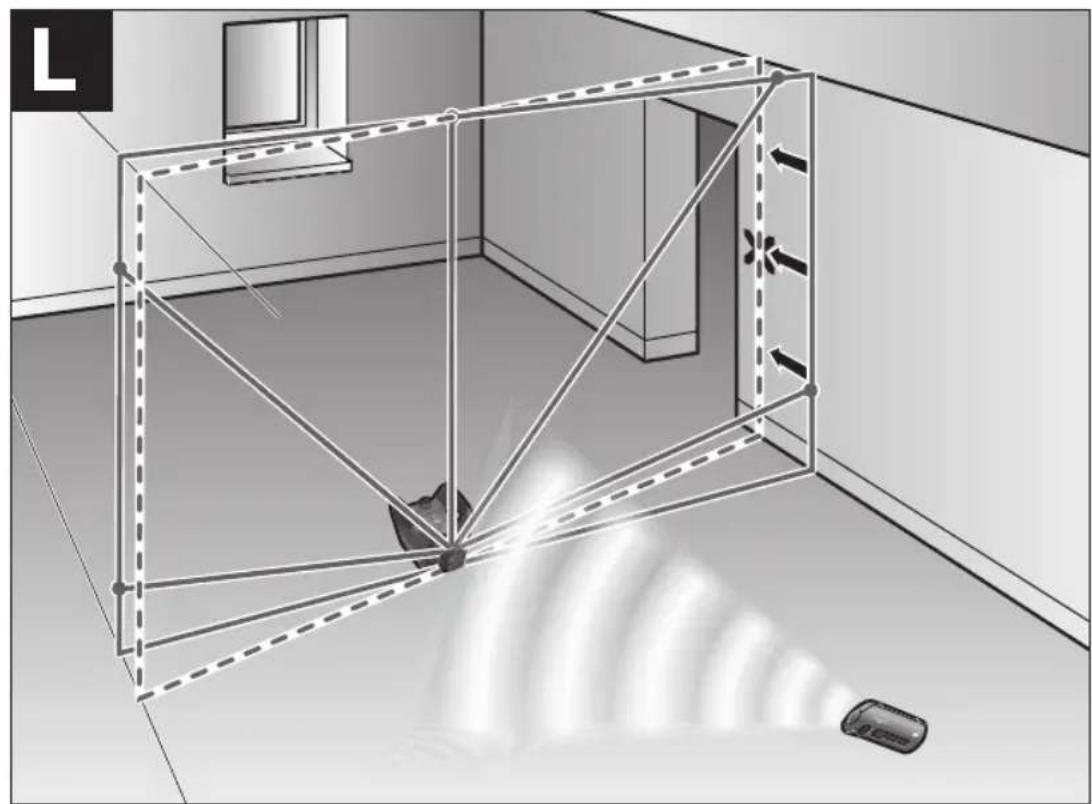
Application Example Turning the Rotational Plane when in the Vertical Position (see figure L)
To align the vertical laser line or the rotational plane against a reference point on a wall,
set up the laser tool in the vertical position, and roughly align the laser line or the rotational plane with the reference point. For precise alignment with the reference point, press button 4c (clockwise rotation) or 5c (counterclockwise rotation).
RC1 Maintenance
Keep the remote control clean at all times.
Do not immerse the remote control into water or other fluids.
Wipe off debris using a moist and soft cloth. Do not use any cleaning agents or solvents.
If the remote control should fail despite the care taken in manufacture and testing, repair should be carried out by an authorized customer services agent for Bosch power tools. Do not open the remote control yourself.
In all correspondence and spare parts orders, please always include the 10-digit article number given on the type plate of the remote control.
ENVIRONMENT PROTECTION
Recycle raw materials & batteries instead of disposing of waste. The unit, accessories, packaging and used batteries should be
sorted for environmentally friendly recycling in accordance with the latest regulations.
LIMITED WARRANTY OF BOSCH LASER AND MEASURINGTOOLPRODUCTS
Robert Bosch Tool Corporation ("Seller") warrants to the original purchaser only, that all Bosch lasers and measuring tools will be free from defects in material or workmanship for a period of one (1) year from date of purchase. Bosch will extend warranty coverage to two (2) years when you register your product within eight (8) weeks after date of purchase. Product registration card must be complete and mailed to Bosch (postmarked within eight weeks after date of purchase), or you may register on-line at www.boschtools.com/Service/ProductRegistration. If you choose not to register your product, a one (1) year limited warranty will apply to your product.
30 Day Money Back Refund or Replacement -
If you are not completely satisfied with the performance of your laser and measuring tools, for any reason, you can return it to your Bosch dealer within 30 days of the date of purchase for a full refund or replacement. To obtain this 30-Day Refund or Replacement, your return must be accompanied by the original receipt for purchase of the laser or optical instrument product. A maximum of 2 returns per customer will be permitted.
SELLER'S SOLE OBLIGATION AND YOUR EXCLUSIVE REMEDY under this Limited Warranty and, to the extent permitted by law, any warranty or condition implied by law, shall be the repair or replacement of parts, without charge, which are defective in material or workmanship and which have not been misused, carelessly handled, or mispaired by persons other than Seller or Authorized Service Center. To make a claim under this Limited Warranty, you must return the complete Bosch laser or measuring tool, transportation prepaid, to any BOSCH Factory Service Center or Authorized Service Center. Please include a dated proof of purchase with your tool. For locations of nearby service centers, please use our on-line service locator or call 1-877-267-2499.
THIS WARRANTY PROGRAM DOES NOT APPLY TO TRIPODS AND RODS. Robert Bosch Tool Corporation ("Seller") warrants tripods and leveling rods for a period of one (1) year from date of purchase.
THIS LIMITED WARRANTY DOES NOT APPLY TO OTHER ACCESSORY ITEMS AND RELATED ITEMS. THESE ITEMS RECEIVE A 90 DAY LIMITED WARRANTY.
To make a claim under this Limited Warranty, you must return the complete product, transportation prepaid. For details to make a claim under this Limited Warranty please visit www.boschtools.com or call 1-877-267-2499.
ANY IMPLIED WARRANTYES SHALL BE LIMITED IN DURATION TO ONE YEAR FROM DATE OF PURCHASE. SOME STATES IN THE U.S., AND SOME CANADIAN PROVINCES DO NOT ALLOW LIMITATIONS ON HOW LONG AN IMPLIED WARRANTY LASTS, SO THE ABOVE LIMITATION MAY NOT APPLY TO YOU.
IN NO EVENT SHALL SELLER BE LIABLE FOR ANY INCIDENTAL OR CONSEQUENTIAL DAMAGES (INCLUDING BUT NOT LIMITED TO LIABILITY FOR LOSS OF PROFITS) ARISING FROM THE SALE OR USE OF THIS PRODUCT. SOME STATES IN THE U.S., AND SOME CANADIAN PROVINCES DO NOT ALLOW THE EXCLUSION OR LIMITATION OF INCIDENTAL OR CONSEQUENTIAL DAMAGES, SO THE ABOVE LIMITATION MAY NOT APPLY TO YOU.
THIS LIMITED WARRANTY GIVES YOU SPECIFIC LEGAL RIGHTS, AND YOU MAY ALSO HAVE OTHER RIGHTS WHICH VARY FROM STATE TO STATE IN THE U.S., OR PROVINCE TO PROVINCE IN CANADA AND FROM COUNTRY TO COUNTRY.
THIS LIMITED WARRANTY APPLIES ONLY TO PRODUCTS SOLD WITHIN THE UNITED STATES OF AMERICA, CANADA AND THE COMMONWEALTH OF PUERTO RICO. FOR WARRANTY COVERAGE WITHIN OTHER COUNTRIES, CONTACT YOUR LOCAL BOSCH DEALER OR IMPORTER.
DO NOT expose the laser tool and battery to rain or wet conditions. Water entering laser tool will increase the risk of fire and personal injury.
NE COURT-CIRCUITEZ PAS de bornes des piles.
NE RECHARGEZ PAS des piles alcalines.
Note: Due to inertia, it is possible for the laser to slightly move beyond the end point of the laser line.

DO NOT expose the laser tool and battery to rain or wet conditions. Water entering laser tool will increase the risk of fire and personal injury.
Industry Canada (IC)
(30mx±0.15mm=±4.5mm)
GRL900-20HV y GRL1000-20HV:
100pi × ± 1 / 8 pulg ± 1 / 8 pulg
(30 ~m × ± 0.10 ~mm = ± 3.0 ~mm)
30 pies x ±1/8 pulp = ±3/64 pulp
(10m× ± 0.1mm = ± 1mm)
Use with Accessories
Selecting the Setting of the Center Indicator
In all correspondence and spare parts orders, please always include the 10-digit article number given on the type plate of the remote control.
© Robert Bosch Tool Corporation 1800 W. Central Road Mt. Prospect, IL 60056-2230
Exportado por: Robert Bosch Tool Corporation Mt. Prospect, IL 60056-2230, E.U.A.
Importado en Mexico por: Robert Bosch, S.A. de C.V., Calle Robert Bosch No. 405, Zona Industrial, Toluca, Edo. de Mexico, C.P. 50070, Tel. (722) 2792300

1609730721
1609730721 10/18
Printed in U.S.A.