JS572EB Professional - Saw BOSCH - Free user manual and instructions
Find the device manual for free JS572EB Professional BOSCH in PDF.


User questions about JS572EB Professional BOSCH
0 question about this device. Answer the ones you know or ask your own.
Ask a new question about this device
Download the instructions for your Saw in PDF format for free! Find your manual JS572EB Professional - BOSCH and take your electronic device back in hand. On this page are published all the documents necessary for the use of your device. JS572EB Professional by BOSCH.
USER MANUAL JS572EB Professional BOSCH
IMPORTANT Read Before Using
IMPORTANT Lire avant usage
IMPORTANTE Leer antes de usar

natural_image
Icon of a person reading a book inside a circle (no text or symbols)Operating/Safety Instructions Consignes d'utilisation/de sécurité Instrucciones de funcionamiento y seguridad
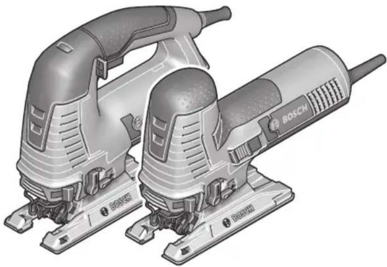
JS572E JS572EB
natural_image
Illustration of two Bosch electric drillers with visible branding (no text or symbols on the devices themselves)
BOSCH
Call Toll Free for Consumer Information and Service Locations Pour obtenir des informations et les adresses de nos centres de service après-vente, appelez ce numéro gratuit Llame gratis para obtener información para el consumidor y ubicaciones de servicio
1-877-BOSCH99 (1-877-267-2499) www.boschtools.com
For English Version See page 2
| Safety SymbolsThe definitions below describe the level of severity for each signal word. Please read the manual and pay attention to these symbols. | |
 | This is the safety alert symbol. It is used to alert you to potential personal injury hazards. Obey all safety messages that follow this symbol to avoid possible injury or death. |
| DANGER indicates a hazardous situation which, if not avoided, will result in death or serious injury. | |
| WARNING indicates a hazardous situation which, if not avoided, could result in death or serious injury. | |
| CAUTION indicates a hazardous situation which, if not avoided, could result in minor or moderate injury. | |
General Power Tool Safety Warnings
WARNING
Read all safety warnings, instructions, illustrations and specifications provided with this power tool. Failure to follow all instructions listed
below may result in electric shock, fire and/or serious injury.
SAVE ALL WARNINGS AND INSTRUCTIONS FOR FUTURE REFERENCE
The term “power tool” in the warnings refers to your mains-operated (corded) power tool or battery-operated (cordless) power tool.
1. Work area safety
a. Keep work area clean and well lit.
Cluttered or dark areas invite accidents.
b. Do not operate power tools in explosive atmospheres, such as in the presence of flammable liquids, gases or dust. Power tools create sparks which may ignite the dust or fumes.
c. Keep children and bystanders away while operating a power tool.
Distractions can cause you to lose control.
2. Electrical safety
a. Power tool plugs must match the outlet. Never modify the plug in any way. Do not use any adapter plugs with earthed (grounded) power tools. Unmodified plugs and matching outlets will reduce risk of electric shock.
b. Avoid body contact with earthed or grounded surfaces, such as pipes, radiators, ranges and refrigerators. There is an increased risk of electric shock if your body is earthed or grounded.
c. Do not expose power tools to rain or wet conditions. Water entering a power tool will increase the risk of electric shock.
d. Do not abuse the cord. Never use the cord for carrying, pulling or unplugging the power tool. Keep cord away from heat, oil, sharp edges or moving parts. Damaged or entangled cords increase the risk of electric shock.
e. When operating a power tool outdoors, use an extension cord suitable for outdoor use. Use of a cord suitable for outdoor use reduces the risk of electric shock.
f. If operating a power tool in a damp location is unavoidable, use a Ground Fault Circuit Interrupter (GFCI) protected supply. Use of an GFCI reduces the risk of electric shock.
3. Personal safety
a. Stay alert, watch what you are doing and use common sense when operating a power tool. Do not use a power tool while you are tired or under the influence of drugs, alcohol or
General Power Tool Safety Warnings
medication. A moment of inattention while operating power tools may result in serious personal injury.
b. Use personal protective equipment. Always wear eye protection. Protective equipment such as dust mask, non-skid safety shoes, hard hat, or hearing protection used for appropriate conditions will reduce personal injuries.
c. Prevent unintentional starting. Ensure the switch is in the off-position before connecting to power source and / or battery pack, picking up or carrying the tool. Carrying power tools with your finger on the switch or energizing power tools that have the switch on invites accidents.
d. Remove any adjusting key or wrench before turning the power tool on. A wrench or a key left attached to a rotating part of the power tool may result in personal injury.
e. Do not overreach. Keep proper footing and balance at all times. This enables better control of the power tool in unexpected situations.
f. Dress properly. Do not wear loose clothing or jewelry. Keep your hair, clothing and gloves away from moving parts. Loose clothes, jewelry or long hair can be caught in moving parts.
g. If devices are provided for the connection of dust extraction and collection facilities, ensure these are connected and properly used. Use of dust collection can reduce dust-related hazards.
h. Do not let familiarity gained from frequent use of tools allow you to become complacent and ignore tool safety principles. A careless action can cause severe injury within a fraction of a second.
4. Power tool use and care
a. Do not force the power tool. Use the correct power tool for your application.
The correct power tool will do the job better and safer at the rate for which it was designed.
b. Do not use the power tool if the switch does not turn it on and off. Any power tool that cannot be controlled with the switch is dangerous and must be repaired.
c. Disconnect the plug from the power source and/or remove the battery pack, if detachable, from the power tool before making any adjustments, changing accessories, or storing power tools. Such preventive safety measures reduce the risk of starting the power tool accidentally.
d. Store idle power tools out of the reach of children and do not allow persons unfamiliar with the power tool or these instructions to operate the power tool.
Power tools are dangerous in the hands of untrained users.
e. Maintain power tools and accessories. Check for misalignment or binding of moving parts, breakage of parts and any other condition that may affect the power tool's operation. If damaged, have the power tool repaired before use. Many accidents are caused by poorly maintained power tools.
f. Keep cutting tools sharp and clean.
Properly maintained cutting tools with sharp cutting edges are less likely to bind and are easier to control.
g. Use the power tool, accessories and tool bits etc. in accordance with these instructions, taking into account the working conditions and the work to be performed. Use of the power tool for operations different from those intended could result in a hazardous situation.
h. Keep handles and grasping surfaces dry, clean and free from oil and grease.
Slippery handles and grasping surfaces do not allow for safe handling and control of the tool in unexpected situations.
5. Service
a. Have your power tool serviced by a qualified repair person using only identical replacement parts. This will ensure that the safety of the power tool is maintained.
Safety Rules for Jig Saws
a. Hold the power tool by insulated gripping surfaces, when performing an operation where the cutting accessory may contact hidden wiring or its own cord. Cutting accessory contacting a "live" wire may make exposed metal parts of the power tool "live" and could give the operator an electric shock.
b. Use clamps or another practical way to secure and support the workpiece to a stable platform. Holding the workpiece by hand or against your body leaves it unstable and may lead to loss of control.
c. Do not drill, fasten or break into existing walls or other blind areas where electrical wiring may exist. If this situation is unavoidable, disconnect all fuses or circuit breakers feeding this worksite.
d. Never leave the trigger locked "ON". Before plugging the tool in, check that the trigger lock is "OFF". Accidental start-ups could cause injury.
e. Be aware of the location and setting of the switch "Lock-ON" button. If the switch is locked "ON" during the use, be ready for emergency situations to switch it "OFF", by first pulling the trigger then immediately releasing it without pressing the "Lock-ON" button.
f. Keep hands away from cutting area. Do not reach under the material being cut. The proximity of the blade to your hand is hidden from your sight.
g. Keep hands from between the gear housing and saw blade holder. The reciprocating blade holder can pinch your fingers.
h. Do not use dull or damaged blades. Bent blade can break easily or cause kickback.
i. Before starting to cut, turn tool "ON" and allow the blade to come to full speed. Tool can chatter or vibrate if blade speed is too slow at beginning of cut and possibly kickback.
j. Always wear safety goggles or eye protection when using this tool. Use a dust mask or respirator for applications which generate dust.
k. Secure material before cutting. Never hold it in your hand or across legs. Small or thin material may flex or vibrate with the blade, causing loss of control.
I. Make certain all adjusting screws and the blade holder are tight before making a cut. Loose adjusting screws and holders can cause the tool or blade to slip and loss of control may result.
Additional Safety Warnings
GFCI and personal protection devices like electrician's rubber gloves and footwear will further enhance your personal safety.
Do not use AC only rated tools with a DC power supply. While the tool may appear to work, the electrical components of the AC rated tool are likely to fail and create a hazard to the operator.
Keep handles dry, clean and free from oil and grease. Slippery hands cannot safely control the power tool.
Develop a periodic maintenance schedule for your tool. When cleaning a tool be careful not to disassemble any portion of the tool since internal wires may be misplaced or pinched or safety guard return springs may be improperly mounted. Certain cleaning agents such as gasoline, carbon tetrachloride, ammonia, etc. may damage plastic parts.
Risk of injury to user. The power cord must only be serviced by a Bosch Factory Service Center or Autho rized Bosch Service Station.
WARNING
Some dust created by power sanding, sawing,
grinding, drilling, and other construction activities contains chemicals known to cause cancer, birth defects or other reproductive harm. Some examples of these chemicals are:
- Lead from lead-based paints,
- Crystalline silica from bricks and cement and other masonry products, and
- Arsenic and chromium from chemically-treated lumber.
Your risk from these exposures varies, depending on how often you do this type of work. To reduce your exposure to these chemicals: work in a well ventilated area, and work with approved safety equipment, such as those dust masks that are specially designed to filter out microscopic particles.
Symbols
IMPORTANT: Some of the following symbols may be used on your tool. Please study them and learn their meaning. Proper interpretation of these symbols will allow you to operate the tool better and safer.
| Symbol Designation/Explanation | |
| V Volts (voltage) | |
| A Amperes (current) | |
| Ah Amp-hour (measurement of battery capacity) | |
| Hz Hertz (frequency, cycles per second) | |
| W Watt (power) | |
| kg Kilograms (weight) | |
| min Minutes (time) | |
| s Seconds (time) | |
| ∅ | Diameter (size of drill bits, grinding wheels, etc.) |
| n_0 | No load speed (rotational speed at no load) |
| n Rated | speed (maximum attainable speed) |
| ../min | Revolutions or reciprocation per minute (revolutions, strokes, surface speed, orbits etc. per minute) |
| 0 Off position (zero speed, zero torque...) | |
| 1, 2, 3, ...I, II, III, | Selector settings (speed, torque or position settings. Higher number means greater speed) |
| 0 | Infinitely variable selector with off (speed is increasing from 0 setting) |
| → | Arrow (action in the direction of arrow) |
| ~ | Alternating current (type or a characteristic of current) |
| == | Direct current (type or a characteristic of current) |
| ~ | Alternating or direct current (type or a characteristic of current) |
| □ | Class II construction (designates double insulated construction tools) |
| ⊕ | Earthing terminal (grounding terminal) |
Symbols (continued)
IMPORTANT: Some of the following symbols may be used on your tool. Please study them and learn their meaning. Proper interpretation of these symbols will allow you to operate the tool better and safer.
| Symbol Designation / Explanation | |
 | Designates Li-ion battery recycling program |
 | Designates Ni-Cad battery recycling program |
 | Alerts user to read manual |
 | Alerts user to wear eye protection |
 | This symbol designates that this tool is listed by Underwriters Laboratories. |
 | This symbol designates that this component is recognized by Underwriters Laboratories. |
 | This symbol designates that this tool is listed by Underwriters Laboratories, to United States and Canadian Standards. |
 | This symbol designates that this tool is listed by the Canadian Standards Association. |
 | This symbol designates that this tool is listed by the Canadian Standards Association, to United States and Canadian Standards. |
 | This symbol designates that this tool is listed by the Intertek Testing Services, to United States and Canadian Standards. |
 | This symbol designates that this tool complies to NOM Mexican Standards. |
Functional Description and Specifications
WARNING
Disconnect the plug from the power source before making any assembly, adjustments or changing accessories. Such preventive safety
measures reduce the risk of starting the tool accidentally.
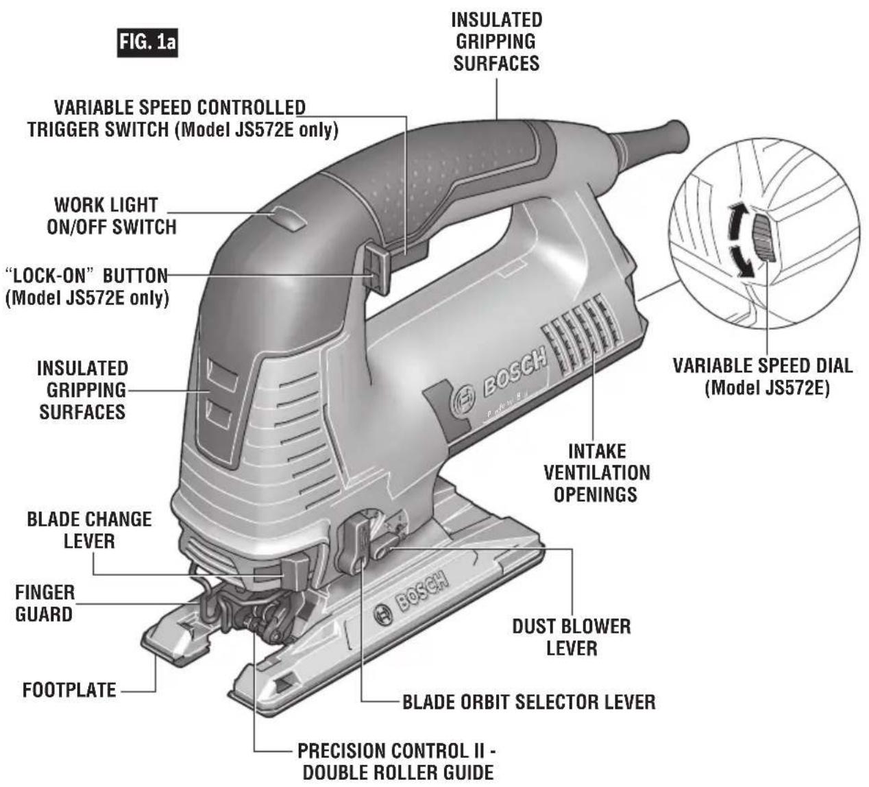
JS572E Jig Saw
text_image
FIG. 1a INSULATED GRIPPING SURFACES VARIABLE SPEED CONTROLLED TRIGGER SWITCH (Model JS572E only) WORK LIGHT ON/OFF SWITCH "LOCK-ON" BUTTON (Model JS572E only) INSULATED GRIPPING SURFACES INTAKE VENTILATION OPENINGS VARIABLE SPEED DIAL (Model JS572E) BLADE CHANGE LEVER FINGER GUARD FOOTPLATE DUST BLOWER LEVER BLADE ORBIT SELECTOR LEVER PRECISION CONTROL II - DOUBLE ROLLER GUIDEFunctional Description and Specifications
Jig Saw JS572EB

text_image
FIG. 1b WORK LIGHT ON/OFF SWITCH INSULATED GRIPPING SURFACES INSULATED GRIPPING SURFACES VARIABLE SPEED DIAL (Model JS572EB) SLIDE ON-OFF SWITCH (Model JS572EB only)| Model number JS572E & JS572EB | ||
| Maximum Capacities | Stroke length 1" (25 mm) | |
| Wood 3-1/2" (89 mm) | ||
| Aluminium 13/16" (20.6 mm) | ||
| Mild steel 5/16" (8 mm) | ||
NOTE: For tool specifications refer to the nameplate on your tool.
Assembly
WARNING
Disconnect the plug from the power source before making any assembly, adjustments or changing accessories. Such preventive safety
measures reduce the risk of starting the tool accidentally.
Blade Installation and Removal
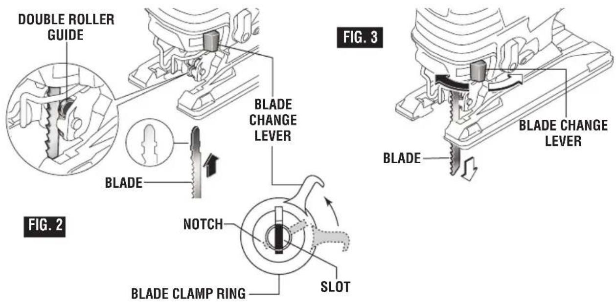
This jigsaw is equipped with a Bosch tool-less blade changing system for fast and easy changes of T-shank blades.
Note: This jigsaw does not accept U-shank blades.
If blade is not properly installed, then the blade may unexpectedly dislodge from jigsaw when tool is energized.
- To remove a previously-used blade, pull blade change lever until blade ejects (Fig. 2).
Blade ejects forcefully when released. Direct away from yourself or bystanders.
-
Pull the blade change lever to the point that the notch on the blade clamp's ring line up with the slot in the center of the clamp (Fig. 2).
-
Insert the saw blade (teeth in cutting direction) until it the "T" part of the blade shank is completely inserted in to the blade clamp. (When inserting the saw blade, the back of the blade must rest in the grooves in double roller guide Fig. 3.)
-
When blade change lever is released, it will spring back to its closed position.
-
Verify that the blade clamp has also returned to its closed position (which is the point where slots were previously).
Note: If the saw blade cannot be inserted into the plunger, the slots of the blade holder are not in the correct position.
Precision Control
The double roller guidance system helps to ensure minimal blade deflection.
text_image
DOUBLE ROLLER GUIDE BLADE NOTCH BLADE CLAMP RING SLOT BLADE CHANGE LEVER BLADE CHANGE LEVER FIG. 2 FIG. 3Assembly
Dust Extraction (Not included, sold separately)
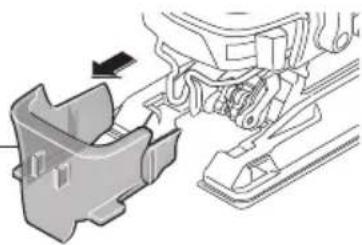
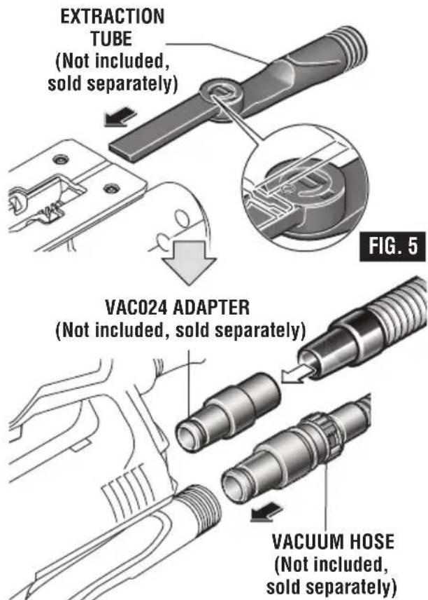
The JA1012 Dust Extraction Kit includes a dust shroud and an extraction tube for connecting the jig saw to a vacuum hose or vacuum hose adapter.
Note: The dust shroud must be used when the extraction tube is connected to a vacuum cleaner system.
To use this feature, insert extraction tube into footplate. (Fig. 4).
FIG. 4
DUST SHROUD (Not included, sold separately)
natural_image
Mechanical assembly diagram showing a component with an arrow indicating direction (no text or symbols present)For vacuuming, a Bosch vacuum hose or hose adapter (sold separately) can be directly connected to the extraction tube (Fig. 5).
text_image
EXTRACTION TUBE (Not included, sold separately) VAC024 ADAPTER (Not included, sold separately) VACUUM HOSE (Not included, sold separately) FIG. 5The VAC024 adapter allows connection to 1-1/4" and 1-1/2" vacuum hoses.
Attaching Steel Overshoe
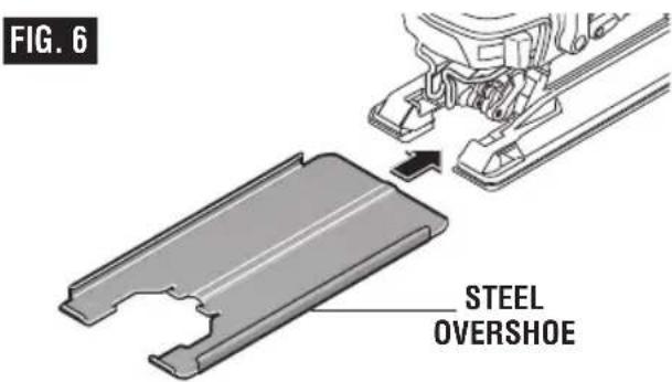
Your tool is equipped with a protective plastic overshoe that protects finer surfaces. An optional heavy-duty steel overshoe for work in rough conditions is sold separately.
To attach, slide overshoe in direction of arrow completely onto metal footplate (Fig. 6).
text_image
FIG. 6 STEEL OVERSHOEAnti-Splinter Insert
To minimize splintering of the top surface of the material being cut, place the JA1013 anti-splinter insert in the blade opening of the footplate's plastic overshoe (Fig. 7).
Note: The anti-splinter insert cannot be used when the footplate is tilted for angle cutting.
Note: This insert will only work with blades that have ground sides such as T301CD, T101B, T101D, and T101DP.
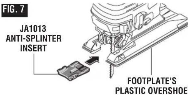
text_image
FIG. 7 JA1013 ANTI-SPLINTER INSERT FOOTPLATE'S PLASTIC OVERSHOEOperating Instructions
WARNING
Disconnect the plug from the power source before making any assembly, adjustments or changing accessories. Such preventive safety
measures reduce the risk of starting the tool accidentally.
Plunger Speed
The jigsaw cutting speed or stroke rate required depends on the material being cut, the type of blade being used, and the feed rate preferred by the operator.
The best speed for a particular application is largely determined by experience though as a general rule, slower speeds are for denser materials and faster speeds for softer materials.
Note: that when the jigsaw is used at low speed settings for an extended length of time, the motor temperature will rise due to slower speeds of the internal cooling fan. In such cases, it is necessary to occasionally run the tool at full speed for a few minutes to keep the motor running at high efficiency.
Variable Speed Dial
Your Jigsaw is equipped with a variable speed dial. The blade stroke rate may be adjusted during cutting operation by presetting the dial on or between any one of the six numbers (Fig. 5).
SPM rating (strokes per minute) Setting JS572E JS572EB
| 1 800 Max. 800 |
| 2 1200 Max. 1200 |
| 3 1700 Max. 1700 |
| 4 2100 Max. 2100 |
| 5 2600 Max. 2600 |
| 6 3000 Max. 3000 |
Slide On-Off Switch (Model JS572EB only)
The tool is switched "ON" by the switch button located at the side of the motor housing. The switch locks in the "ON" position, a convenience for continuous operation (Fig. 1).
To turn the tool "ON" slide the switch button forward.
TO UNLOCK THE SWITCH, slide the switch button backward.
Variable Speed Controlled Trigger Switch (Model JS572E only)
Your tool is equipped with a variable speed trigger switch. The tool can be turned "ON" or "OFF" by squeezing or releasing the trigger. The speed can be adjusted from the minimum to maximum SPM as set on the variable speed dial by the pressure you apply to the trigger. Apply more pressure to increase the speed and release pressure to decrease speed.
Regardless of the pressure applied on the trigger, the tool will not operate any faster than maximum speed setting selected on the variable speed dial.
"Lock-On" Button (Model JS572E only)
The "Lock-ON" button, located in the handle of your tool allows for continuous operation at maximum preset SPM without holding the trigger (Fig. 1).
TO LOCK TRIGGER "ON": squeeze trigger, depress button and release trigger.
TO UNLOCK THE TRIGGER: squeeze trigger and release it without depressing the "Lock-ON" button.
WARNING
If the "Lock-ON" button is continuously being
depressed, the trigger can not be released.
Work Light
Your tool is equipped with a work light for better visibility during operation. The tool power cord must be plugged into a power source before you activate the light. To turn light ON depress the work light ON/OFF switch. To turn light off depress the ON/OFF switch again (Fig. 1).
Operating Instructions
Constant Response Circuitry
The internal electronic feedback system provides a "soft start", which will reduce the stresses that occur from a high torque start. The system also maintains the selected speed under load for maximum efficiency.
Blade Orbit Selector Lever
Maximum cutting efficiency can be obtained by adjusting the blade orbit selector lever to suit the material being cut.
The following chart will help you determine which setting to use for your application. This chart is intended as a guideline only, and test cuts in scrap material should be performed first to determine the best setting.
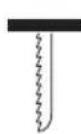
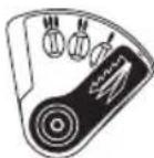
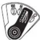
Setting O
Hard materials such as metals or thin sheet metals. This setting can be used with knife blades, grit edge blades, rasp work and down cutting blades.
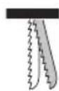
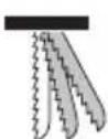
Setting I
Soft materials where cleaner cutting or delicate scrolling work is performed.
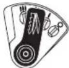
Setting II
Medium density materials such as harder woods or particle board.
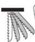
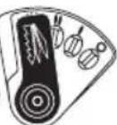
Setting III
Soft materials such as wood, plastics, etc. and when fast cutting is more important than a clean cut.
Chip Blower
Your jig saw is equipped with a two position chip blower to help keep the cutting line clear of chips.
By adjusting the chip blower lever the force of the discharge air may be altered as follows;
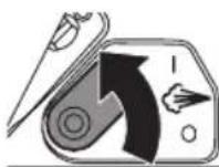
BLOWER SWITCHED ON
For working with wood, plastic and similar materials that produce large amounts of sawdust.
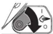
BLOWER SWITCHED OFF
For working with metals and when cooling agents are used, or with dust collection accessory.
Footplate Angle Adjustment
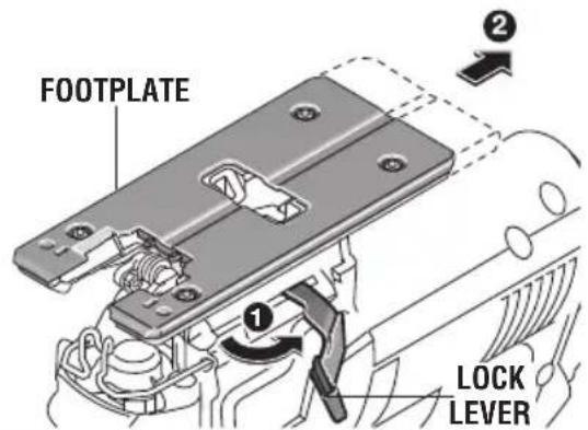
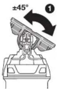
The footplate may be tilted to allow angle cuts up to 45^ in either direction (Fig. 8).
Note: before adjusting the footplate, remove dust shroud and anti-splinter if used.
Open the lock lever to unlock footplate. Push and hold the footplate firmly towards the back of tool as shown. While holding the footplate backwards tilt footplate to desired angle on bevel scale, then release pressure on footplate so it engages into detent at desired angle (Fig. 8).
text_image
FOOTPLATE 1 2 LOCK LEVERFIG. 8
text_image
±45° ①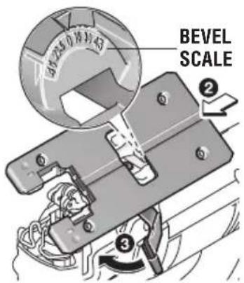
text_image
BEVEL SCALEOperating Instructions
Your tool has detent slots the footplate will engage at 0^ & 45^ , and there are additional position marks for 15^ , 22.5^ and 30^ angles.
Close the lock lever slowly to assure that footplate is locked at the desired angle.
Tool Tips
WARNING Always hold the saw by the insulated
gripping surfaces on the front of the tool and the switch handle. Failure to hold the tool by the insulated gripping surface may result in electric shock or electrocution if sawing into a blind area where live wiring exits.
Always be certain that smaller workpieces are securely fastened to a bench or other support. Larger panels may be held in place by clamps on a bench or sawhorses.
To begin a cut, clearly mark the cutting line, and rest the front of the footplate on the work. Engage the switch, and move the blade into the work using only enough forward pressure to keep the blade cutting steadily. Do not force, as this will not make the saw cut faster; let the blade do the work.
Choose blades carefully, as the ability of the jigsaw to follow curves, provide smoother finishes, or faster cutting is directly related to the type of blade used (See your Bosch Dealer).
For tight curves it is best to use a narrow or scroll blade.
When sawing metal or similar materials, shut off chip blower and apply coolant/lubricant alongside the cutting line. Don't use extraction.
Use of reverse-tooth blade such as the Bosch T101BR requires the orbital setting to be "0" and that downward pressure be applied to the top of the saw.
Plunge cutting
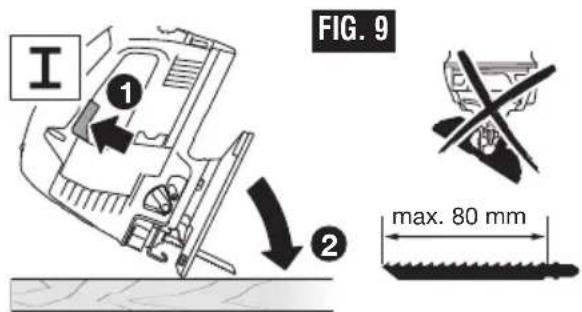
Plunge cutting is useful and time-saving in making rough openings in softer materials. It is not necessary to drill a hole for an inside or pocket cut. The longest blade to be used for plunge cutting is 3-1/8" (80 mm). Footplate must be set 0° setting. (Fig. 9).
text_image
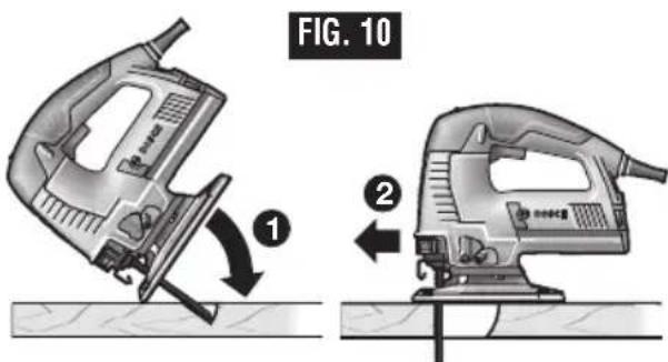
FIG. 9 max. 80 mmDraw lines for the opening, hold the saw firmly, tilt it forward so that the toe of the saw foot rests on the work, but with the blade well clear of the work. Turn the tool on and run at top speed, and then very gradually lower the blade (Fig. 10).
text_image
FIG. 10 ① ②When it touches, continue pressing down on the toe of the saw foot slowly pivoting the saw like a hinge until the blade cuts through and the foot rests flat on the work. Then saw ahead on the cutting line. We do not recommend plunge cutting with a scroll blade. Do not try to plunge cut into hard materials such as steel.
To make sharp corners, cut up to the corner, then back up slightly before rounding the corner. After the opening is complete, go back to each corner and cut it from the opposite direction to square it off.
Operating Instructions
JA1010 Circle and Parallel Cutting Guide
(Sold separately)
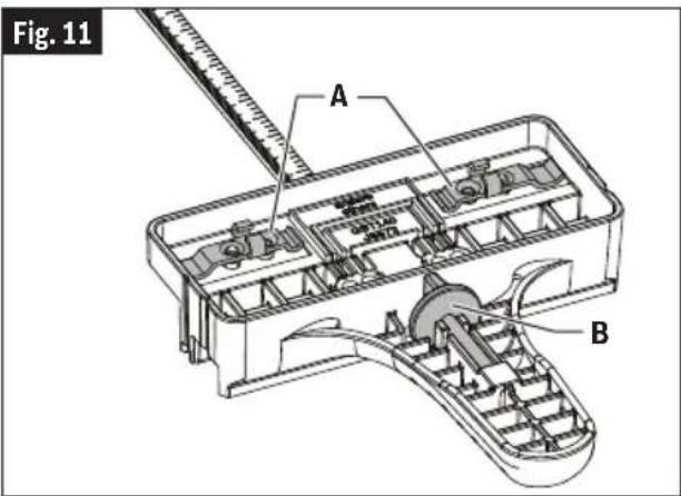
The JA1010 is used for fast and accurate straight and circle cutting. It includes the guide, two clamps A for attaching it to the jig saw, and a center pin B for guiding circle cuts. The clamps and the centering pin can be stored on the guide (Fig. 11).
One end of the clamp is used to attach the guide's bar to jig saws that have narrow tops on their footplate mounting slots (C) and the other end is used to attach the guide's bar to jig saws that have wide tops on their footplate mounting slots (D) (Fig. 12).
When possible, attach the bar to the jig saw using both clamps for enhanced grip and precision.
ATTACHING GUIDE TO JIG SAW
- Orient the blade clamp so that the proper end is placed on the jig saw foot from either side of the tool.
- Insert guide's bar through a clamp, then through the slots provided in foot, with the guide's fence orientated correctly for the intended application, parallel cutting or circle cutting. (If possible, place second clamp on bar from opposite side of jig saw.)
- Place lock knob(s) on proper side of clamp(s) and securely tighten lock knob(s) on the clamp(s) (Fig. 13).
PARALLEL CUTTING
Parallel cuts can be made from 5/8" to 6" in from the edge of the workpiece.
- The guide fence surface needs to be positioned ALONGSIDE the workpiece (Fig. 14).
- Hook clamp(s) onto footplate, adjust fence to desired width and place lock knob(s) on proper side of clamp(s)
- Securely tighten lock knob(s) on the clamp(s) (Fig. 13).
- Insert jig saw's plug into power source, hold the saw firmly, squeeze trigger and slowly push the saw forward (Fig. 14).
text_image
Fig. 11 A B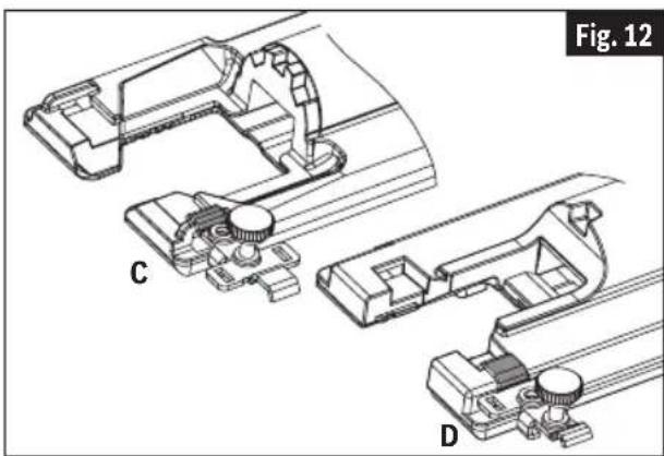
natural_image
Technical line drawing of mechanical components labeled C and D, showing assembly or assembly steps without any readable text or symbols.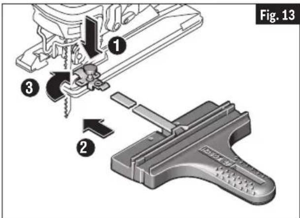
text_image
Fig. 13 ① ③ ②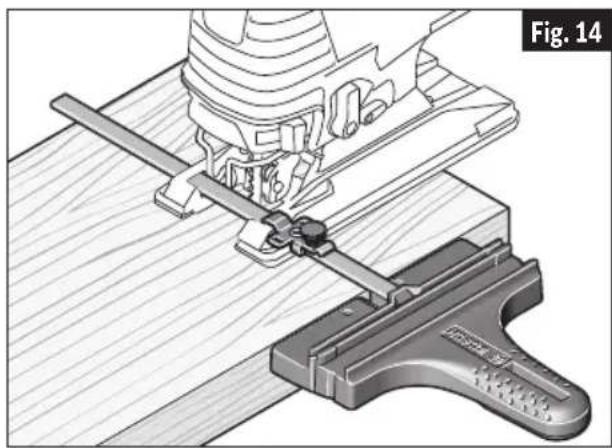
natural_image
Technical illustration of a mechanical clamp assembly with a wooden base and clamping tool (no text or symbols)Operating Instructions
CIRCLE CUTTING
Circle cuts can be made from 5" to 16-1/2" in diameter
- Determine the center point of the desired circle.
-
Drill a 3/16" (5 mm) center hole 7/8" (23 mm) deep in workpiece. (For enhanced precision, drill the hole using a drill press, if possible).
-
Drill or plunge cut near the circle's edge, turn saw off, and disconnect the plug from power source.
-
Insert guide bar through a clamp, then through the slots provided in foot, from either side of foot (Fig. 15). (If possible, place second clamp on bar from opposite side of jig saw).
-
Remove guide pin B from end of guide, push pin through proper hole provided in guide, then into center hole of workpiece. (When used with a Bosch JS572 jig saw – or the JSH180 cordless jig saw – the holes labeled for the JS572 should be used.) For other jig saws, one of the other holes should be used.
-
Measure the distance from the center of the hole to the desired circle radius. Adjust that measurement as necessary to account for the width of the blade:
-
When cutting a hole, cut from inside the intended radius.
-
When cutting wheels or discs, cut from the outside the intended radius.
-
Hook clamp(s) onto footplate, and position the guide to that adjusted radius measurement.
-
Place lock knob(s) on proper side of clamp(s) and securely tighten lock knob(s) on the clamp(s) (Fig. 13).
-
Insert jig saw's plug into power source, hold the saw firmly, squeeze trigger and slowly push the saw forward.

text_image
Fig. 15 A B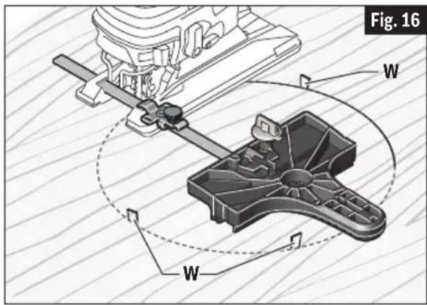
text_image
Fig. 16 W WCIRCLE-CUTTING TIPS:
- Place small wedges W in the cut as shown in Fig. 16, to keep the inner circle from spreading when near the end of the cut.
- Use a thick jig saw blade, such as the Bosh T101TP or T144DP whenever possible.
- Make sure that the jig saw's orbital setting is at 0 (zero)
- Cut slowly so the blade will stay straight in the cut.
Maintenance
WARNING
To avoid accidents, always disconnect the battery pack from tool before servicing or cleaning.
Service
WARNING
Preventive maintenance performed by un au - thorized personnel may result in misplacing of internal wires and components which could cause serious
hazard. We recommend that all tool service be performed by a Bosch Factory Service Center or Authorized Bosch Service Station. SERVICE MEN: Disconnect tool and/or charger from power source before servicing.
Tool Lubrication
Your Bosch tool has been properly lubricated and is ready for use. It is recommended that tools with gears be regreased with a special gear lubricant at every brush change.
Carbon Brushes
The brushes and commutator in your tool have been engineered for many hours of dependable service. To maintain peak efficiency of the motor, we recommend every two to six months the brush es be examined. Only genuine Bosch replace ment brushes specially designed for your tool should be used.
Bearings
Bearings which become noisy (due to heavy load or very abrasive material cutting) should be replaced at once to avoid overheating and motor failure.
Cleaning
CAUTION
Certain cleaning agents and solvents damage plastic parts. Some of these are: gasoline, carbon tetrachloride, chlorinated cleaning solvents, ammonia and household detergents that contain ammonia.
Ventilation openings and switch levers must be kept clean and free of foreign matter. Do not attempt to clean by inserting pointed objects through opening.
Cleaning Blade Holder
Clean the saw blade holder regularly. For this, remove the saw blade from the tool and lightly tap footplate on a level surface.
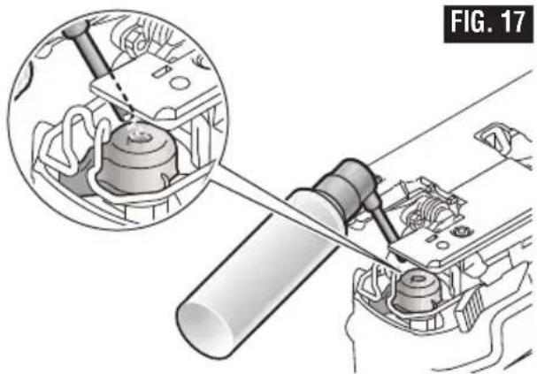
Regularly spray penetrating oil onto the saw blade holder (Fig. 17).
natural_image
Mechanical assembly diagram showing a tool interacting with a component, with an inset close-up of the mechanical part (no text or symbols visible)Check the guide roller regularly. If worn, it must be replaced through an authorized Bosch Factory Service Center
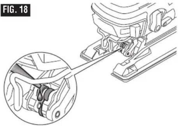
Lubricate the guide roller occasionally with a drop of oil (Fig. 18).
natural_image
Mechanical assembly diagram showing a bracket with a close-up inset of the component (no text or symbols)Extension Cords
WARNING
If an extension cord is necessary, a cord with adequate size conductors that is capable of carrying the current necessary for your tool must be used. This will prevent excessive voltage drop, loss of power or overheating. Grounded tools must use 3-wire extension cords that have 3-prong plugs and receptacles.
NOTE: The smaller the gauge number, the heavier the cord.
RECOMMENDED SIZES OF EXTENSION CORDS 120 VOLT ALTERNATING CURRENT TOOLS
| Tool's Ampere Rating | Cord Size in A.W.G. | Wire Sizes in mm 2 | ||||||
| Cord Length in Feet Cord | Cord Length in Meters | |||||||
| 25 | 50 | 100 | 150 | 15 | 30 | 60 | 120 | |
| 3-6 | 18 | 16 | 16 | 14 | 0.75 | 0.75 | 1.5 | 2.5 |
| 6-8 | 18 | 16 | 14 | 12 | 0.75 | 1.0 | 2.5 | 4.0 |
| 8-10 | 18 | 16 | 14 | 12 | 0.75 | 1.0 | 2.5 | 4.0 |
| 10-12 | 16 | 16 | 14 | 12 | 1.0 | 2.5 | 4.0 | - |
| 12-16 | 14 | 12 | - | - | - | - | - | - |
Accessories and Attachments
WARNING
The use of any other attachments or acces so ries not specified in this manual may create a hazard.
Store accessories in a dry and temperate environment to avoid corrosion and deterioration.
text_image
I FIG. 9 ① ② max. 80 mmtext_image
FIG. 10 ① ②natural_image
Technical line drawing of mechanical components labeled C and D, showing assembly or assembly steps without any readable text or symbols.natural_image
Technical illustration of a mechanical clamp tool operating on a wooden workbench, labeled Fig. 14 (no text or symbols on the diagram itself)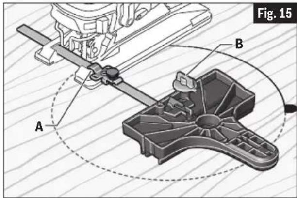
text_image
Fig. 15 A Btext_image
Fig. 16 W WCONSEILS POUR LES COUPES CIRCULAIRES :
natural_image
Mechanical assembly diagram showing a tool interacting with a component, with an inset close-up of the mechanical part (no text or symbols visible)natural_image
Mechanical assembly diagram showing a lever mechanism with a magnified inset of the component (no text or symbols)Cordons de rallonge
AVERTISSEMENT
text_image
±45° ① ESCALA DE BISEL ② ③text_image
I FIG. 9 ① ② max. 80 mmCorte mediante descenso vertical
text_image
FIG. 10 ① ②natural_image
Technical line drawing of mechanical components labeled C and D, showing assembly or assembly steps without any readable text or symbols.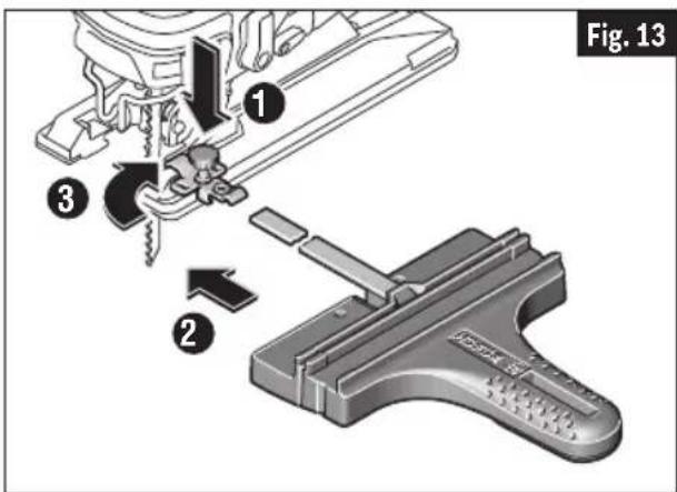
text_image
Fig. 13 ① ③ ②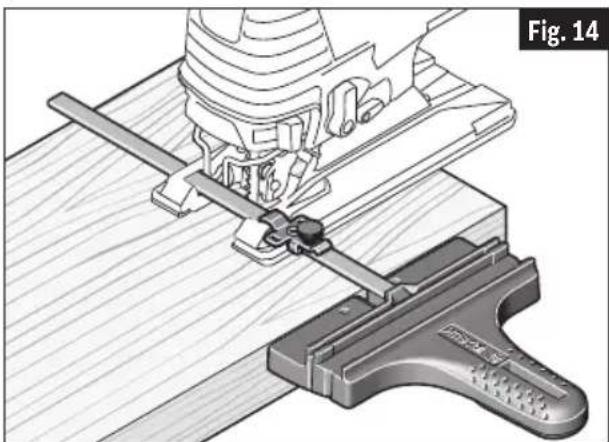
natural_image
Technical illustration of a mechanical clamp tool operating on a wooden workbench, labeled Fig. 14 (no text or symbols on the diagram itself)CORTE DE CÍRCULOS
text_image
Fig. 16 W Wnatural_image
Mechanical assembly diagram showing a tool interacting with a component, with an inset close-up of the tool inside (no text or symbols)natural_image
Mechanical assembly diagram showing a lever mechanism with a magnified inset view of the component (no text or symbols present)Robert Bosch Tool Corporation ("Seller") warrants to the original purchaser only, that all BOSCH portable and benchtop power tools will be free from defects in material or workmanship for a period of one year from date of purchase. SELLER'S SOLE OBLIGATION AND YOUR EXCLUSIVE REMEDY under this Limited Warranty and, to the extent permitted by law, any warranty or condition implied by law, shall be the repair or replacement of parts, without charge, which are defective in material or workmanship and which have not been misused, carelessly handled, or misrepaired by persons other than Seller or Authorized Service Station. To make a claim under this Limited Warranty, you must return the complete portable or benchtop power tool product, transportation prepaid, to any BOSCH Factory Service Center or Authorized Service Station. For Authorized BOSCH Power Tool Service Stations, please refer to your phone directory.
THIS LIMITED WARRANTY DOES NOT APPLY TO ACCESSORY ITEMS SUCH AS CIRCULAR SAW BLADES, DRILL BITS, ROUTER BITS, JIGSAW BLADES, SANDING BELTS, GRINDING WHEELS AND OTHER RELATED ITEMS.
ANY IMPLIED WARRANTIES SHALL BE LIMITED IN DURATION TO ONE YEAR FROM DATE OF PURCHASE. SOME STATES IN THE U.S., SOME CANADIAN PROVINCES DO NOT ALLOW LIMITATIONS ON HOW LONG AN IMPLIED WARRANTY LASTS, SO THE ABOVE LIMITATION MAY NOT APPLY TO YOU.
IN NO EVENT SHALL SELLER BE LIABLE FOR ANY INCIDENTAL OR CONSEQUENTIAL DAMAGES (INCLUDING BUT NOT LIMITED TO LIABILITY FOR LOSS OF PROFITS) ARISING FROM THE SALE OR USE OF THIS PRODUCT. SOME STATES IN THE U.S. AND SOME CANADIAN PROVINCES DO NOT ALLOW THE EXCLUSION OR LIMITATION OF INCIDENTAL OR CONSEQUENTIAL DAMAGES, SO THE ABOVE LIMITATION OR EXCLUSION MAY NOT APPLY TO YOU.
THIS LIMITED WARRANTY GIVES YOU SPECIFIC LEGAL RIGHTS, AND YOU MAY ALSO HAVE OTHER RIGHTS WHICH VARY FROM STATE TO STATE IN THE U.S., PROVINCE TO PROVINCE IN CANADA AND FROM COUNTRY TO COUNTRY.
THIS LIMITED WARRANTY APPLIES ONLY TO PORTABLE AND BENCHTOP ELECTRIC TOOLS SOLD WITHIN THE UNITED STATES OF AMERICA, CANADA AND THE COMMONWEALTH OF PUERTO RICO. FOR WARRANTY COVERAGE WITHIN OTHER COUNTRIES, CONTACT YOUR LOCAL BOSCH DEALER OR IMPORTER.
GARANTIE LIMITÉE DES OUTILS ÉLECTRIQUES PORTATIFS ET D'ÉTABLI BOSCH
© Robert Bosch Tool Corporation 1800 W. Central Road Mt. Prospect, IL 60056-2230
Exportado por: Robert Bosch Tool Corporation Mt. Prospect, IL 60056-2230, E.U.A.