Compact B0CHW4KGXN - Food dispenser Dörr - Free user manual and instructions
Find the device manual for free Compact B0CHW4KGXN Dörr in PDF.

| Product type | Automatic food dispenser |
| Brand | Dörr |
| Model | Compact B0CHW4KGXN |
| Dimensions (without container) | Approx. 14 × 14 × 13.8 cm |
| Dimensions (with container) | Approx. 25 × 25 × 40 cm |
| Weight (without container) | Approx. 450 g |
| Weight (with container) | Approx. 2150 g |
| Container capacity (model with) | Approx. 20 kg / 25 liters |
| Power supply | 4 AA LR6 1.5 V batteries or equivalent rechargeable batteries (not included); connection for optional 6 V solar panel |
| Number of programmable feedings per day | 1 to 4 |
| Adjustable spreading duration | 1 to 30 seconds |
| Spreading range | Approx. 7 meters (depending on the feed) |
| Dispensed quantity | Approx. 125 g of whole grain corn per second |
| Selectable working days | Yes, individually for each day of the week |
| Test function | Yes, adjustable duration from 1 to 30 seconds |
| Display | Digital screen with adjustment of time, days, and durations |
| Materials | Plastic, metal spreading disc |
| Care and cleaning | Clean with a slightly damp microfiber cloth; do not immerse in water; remove batteries before cleaning |
| Safety - safety distance | Keep a distance of at least 8 meters during operation |
| Safety - usage | Do not use indoors; protect eyes and limbs; do not put hands inside the housing |
| Spare parts and repairability | Repair by customer service only; no spare parts provided |
| General information | Compliant with European directives (CE, RoHS, WEEE) |
Frequently Asked Questions - Compact B0CHW4KGXN Dörr
User questions about Compact B0CHW4KGXN Dörr
0 question about this device. Answer the ones you know or ask your own.
Ask a new question about this device
Download the instructions for your Food dispenser in PDF format for free! Find your manual Compact B0CHW4KGXN - Dörr and take your electronic device back in hand. On this page are published all the documents necessary for the use of your device. Compact B0CHW4KGXN by Dörr.
USER MANUAL Compact B0CHW4KGXN Dörr
DÖRR
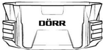
natural_image
Line drawing of a container with 'DÖRR' branding on the side (no other text or symbols)
natural_image
Technical line drawing of a mechanical component with labeled DÖRR (no other text or symbols)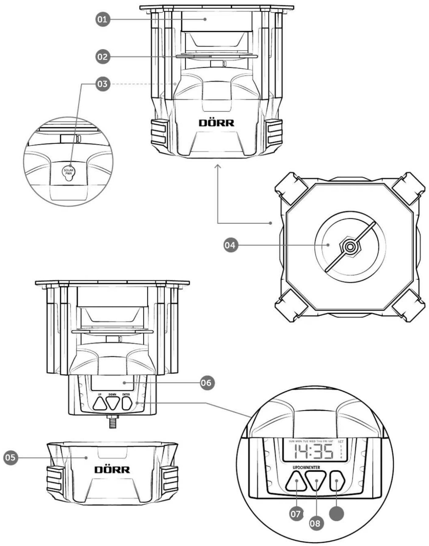
natural_image
Technical diagram of a circular mechanical component with concentric rings and mounting holes (no text or symbols)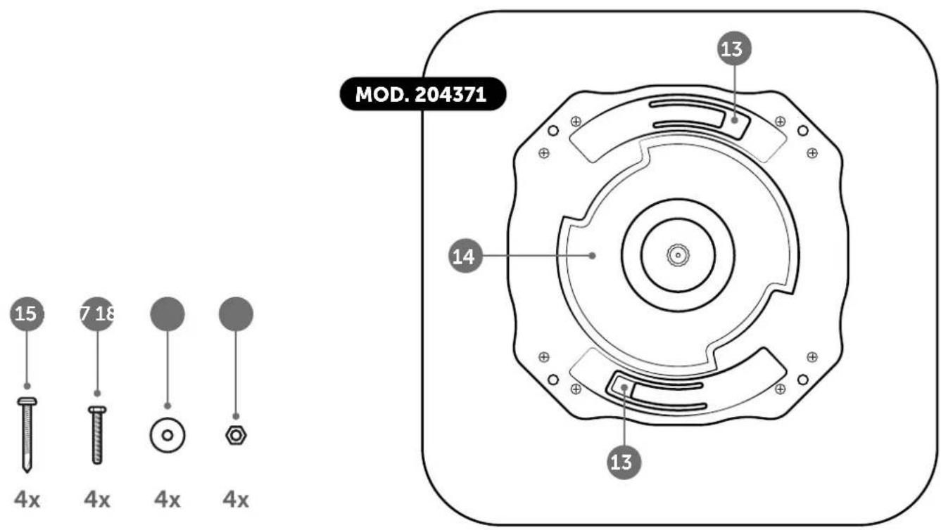
DEUTSCH
8 Taste DOWN ▽ (runter)
natural_image
Cross-sectional diagram of a mechanical piston assembly with internal components and directional arrows (no text or labels)06 | INBETRIEBNAHME
06.1 BATTERIEN EINLEGEN
WICHTIG
natural_image
Cross-sectional diagram of a mechanical assembly with internal components (no text or labels)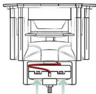
natural_image
Cross-sectional diagram of a mechanical assembly with internal components and directional arrows (no text or labels)natural_image
Technical line drawing of a mechanical device with a red cable inserted into a base (no text or symbols)06.2 BATTERIEWECHSEL
HINWEIS
08 | TEST FUNKTION
√ 12.4 ROHS KONFORMITÄT
THANK YOU for choosing a quality product from DÖRR.
Please read the instruction manual and the safety hints carefully before using the device for the first time.
Keep the operating instructions together with the device for reference. If other people use this device, provide them with these instructions. If you sell the unit, this manual forms an integral part of the device and must be supplied with it.
DÖRR is not liable for damage caused by improper use or failure to observe the operating and safety instructions.
In the event of damage caused by improper handling or by external influence, the guarantee or warranty claim becomes void. Any manipulation, structural modification of the product or opening of the housing by the user or an unauthorised third party shall be considered improper handling.
SYMBOLS IN THIS INSTRUCTION MANUAL
CAUTION
This symbol is to alert you to potential hazards that could result in serious bodily injury and/or property damage.
IMPORTANT
This symbol indicates important information that must be observed to ensure smooth operation of the product.
NOTICE
This symbol indicates useful tips and tricks that will help you use the product.
01 | SAFETY HINTS
- Keep a distance of minimum 8m from the feeder for both test and regular operation!
- Protect your eyes and extremities! The fast rotation of the feeding engine and the ejected feed can be harmful.
- ▲ Never reach into the housing and the spinner plat during operation - there is a risk of cut injuries and amputation of fingers!
Not for use in closed rooms!
This device is not a toy! To prevent accidents and suffocation keep the device, the accessories and the packing materials away from children and pets.
- ▲ People with physical or cognitive disabilities should use the device with supervision.
- ▲ People with cardiac pacemakers, defibrillators or any other electrical implants should maintain a minimum distance of 30 cm, as the device generates magnetic fields.
- Make sure to use the device only with appropriate, high-quality batteries type Mignon AA LR6 1.5V or equivalent rechargeable AA batteries (not included). When inserting the batteries, pay attention to the correct polarity (+/-). Please remove batteries when device is not in use for a long period of time.
- Turn off the device after use.
- Do not operate or touch the device with wet hands. ⚠️ Risk of electric shock!
- Do not submerge or throw the feeder into water.
- Protect the device against impacts. Do not use the device if it has been dropped. In this case a qualified electrician should inspect the device before you use it again.
- If the device is defective or damaged, do not attempt to disassemble or repair it yourself – ⚠ there is a risk of electric shock! If maintenance or repair is required, please contact our service department.
- Protect the device from dirt. Do not clean the device with benzine or harsh cleaning agents. We recommend using a lint-free, slightly damp micro-fibre cloth to clean the external components of the device. ⚠ Never immerse the device in water for cleaning. ⚠ Before cleaning, switch off the device and remove the batteries.
- Store the device in a dust-free, dry and cool place. ⚠️ Keep the device out of reach of children. Keep the device away from pets.
- At the end of its service life, please dispose of the device in accordance with the Waste Electrical and
Electronic Equipment Directive (WEEE Directive) or the applicable national regulations, e.g. the ElektroG in Germany. For information on proper disposal, please contact your local waste disposal authority or the relevant authorities.
02 | SAFETY HINTS FOR BATTERIES
Make sure to use the device only with appropriate, high-quality batteries type Mignon AA LR6 1.5V or equivalent rechargeable AA batteries (not included). When inserting the batteries, pay attention to the correct polarity (+/-). Do not insert batteries of different types and always replace all batteries at the same time. Do not combine used batteries with fresh batteries. Please remove batteries when device is not in use for a longer period. ⚠️ Do not throw the batteries into fire, do not short-circuit and do not disassemble them! ⚠️ Never charge non-rechargeable batteries – risk of explosion! Remove empty batteries immediately from the device to avoid the leaking of battery acid. Remove leaking batteries from the device immediately. Clean the contacts before inserting fresh batteries. ⚠️ Risk of battery acid burn! In case of contact with battery acid, rinse the affected area immediately with water and contact a doctor. Batteries can be dangerous to life if swallowed. ⚠️ Keep batteries away from small children and pets. Do not dispose of batteries in household waste (see also capture „Disposal of Batteries/Accumulators“).
03 | PRODUCT DESCRIPTION
The DÖRR „Compact“ feeder helps to manage feeding in your hunting ground. It reliably spreads e.g. corn at certain times. It can be used to avoid damages caused by game in hunting ground as a distraction feeding.
• Spreads e.g. corn, cereals, feed pellets and more
• Digital timer to select 1 – 4 feeding times per day
- Working days selectable
- Feeding time adjustable from 1 – 30 seconds
- Spreads about 125 g corn (whole grains) per second
- Spreading range up to 7 m (depending on weight and size of feed pieces)
• Operation via 4x AA batteries LR6 1,5V (not included)
- Connection for optional 6V solar panel
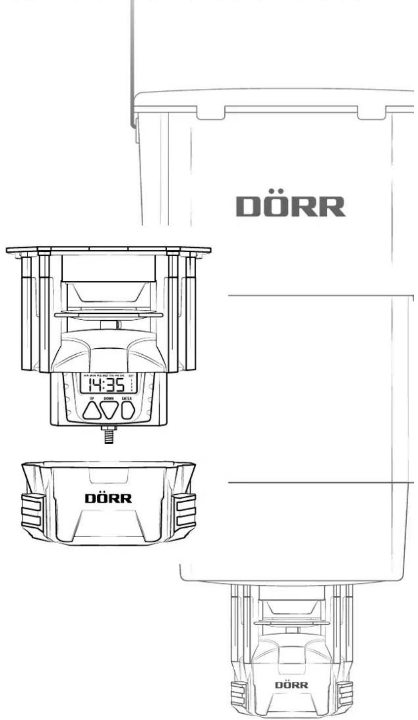
04 | NOMENCLATURE
01 Feeder housing
02 Metal spinner plat
03 Connection for optional 6V solar panel
04 Locking screw
05 Housing cover battery compartment + timer
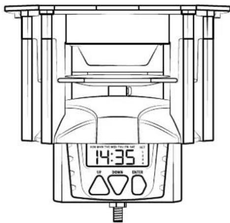
06 Display
07 Button UP △
08 Button DOWN ▽
09 Button ENTER D
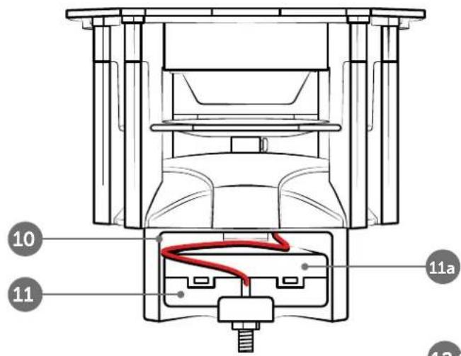
10 Battery compartment
11 Battery box
11a) Cover battery box
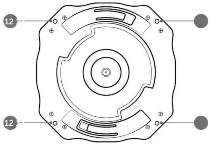
12 4 mounting holes (ø 4mm)
13* Quick-lock adapter
14* Release clips
15 4 pcs self-tapping screws
16 4 pcs Hex bolts M4 x 25mm
17 4 pcs washers M4
18 4 pcs Hex nuts M4
* Only model No. 204371 with container
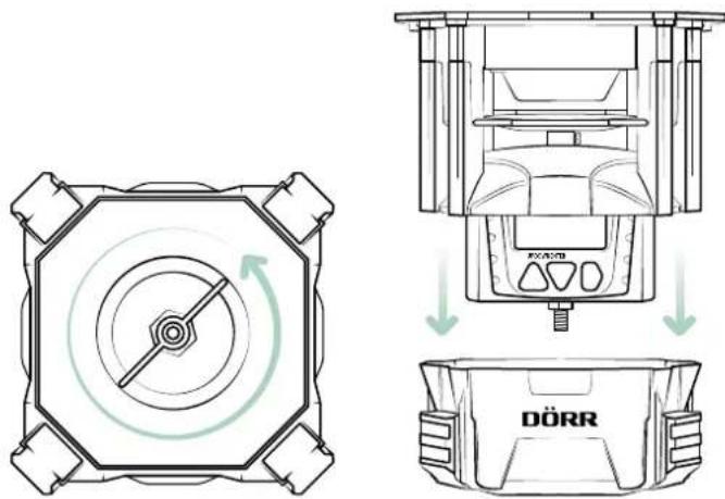
05 | MOUNTING ONTO A FEED CONTAINER
05.1 MODEL 204370 (WITHOUT CONTAINER)
Mount the feeder on a suitable feed container (optionally available in stores) by screwing it through the 4 mounting holes (12) using the supplied screws, washers and nuts (16-18).
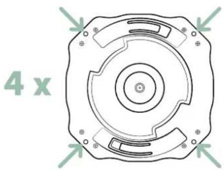
natural_image
Technical diagram of a circular mechanical component with four mounting holes and concentric rings (no text or symbols)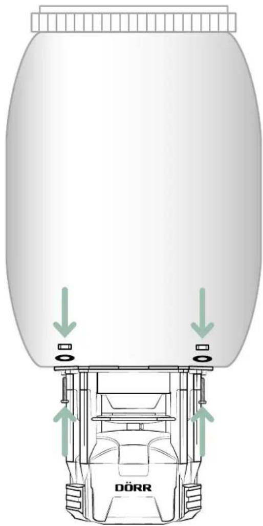
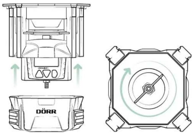
05.2 MODEL 204371 (WITH CONTAINER)
With the quick-lock adapters (13) on top of the feeder and on the bottom of the feed container, the feeder can be easily attached to the container. Turn the feeder to the right until it clicks audible into place.
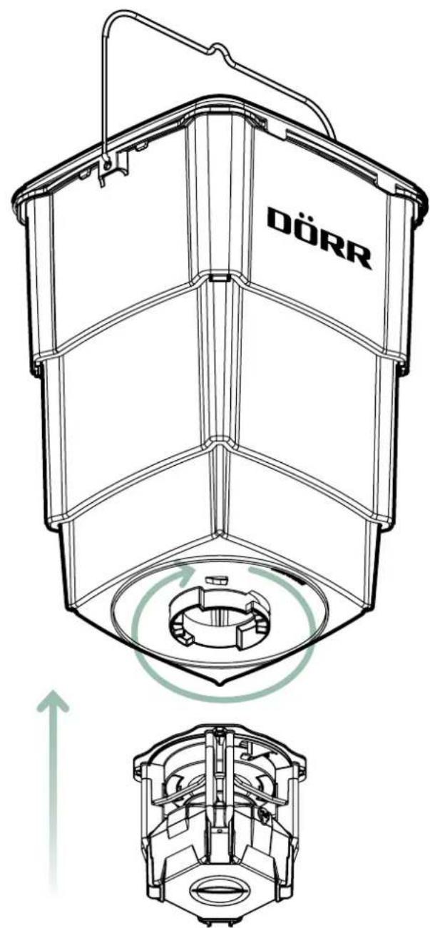

NOTICE
You will only require the supplied screws, washers and nuts (16-18) if you wish to mount another suitable feed container, e.g. a barrel, onto the feed spreader.
To remove the feed container, pull the two release clips (14) down and turn the feed to the left.
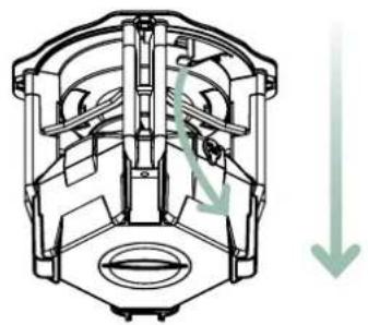
natural_image
Cross-sectional diagram of a mechanical component with internal channels and directional arrows (no text or labels)06 | FIRST STEPS
06.1 INSERT BATTERIES
IMPORTANT
Make sure to use the device only with appropriate, high-quality batteries type Mignon AA LR6 1,5V or equivalent rechargeable AA batteries (not included). When inserting the batteries, pay attention to the correct polarity (+/-). Please remove batteries when device is not in use for a long period of time.
Favourable battery value packs can be found in our DÖRR web shop doerr.shop.
Unscrew the locking screw (04) on the bottom of the feeder until you can remove the lower housing cover (05).
The battery compartment (10) with the battery box (11) is located on the rear side of the feeder.
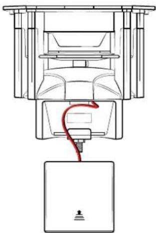
To remove the battery box (11), push it up with both thumbs until the battery box clicks out of the holder.
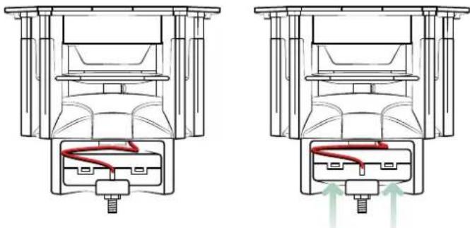
natural_image
Technical line drawing of a mechanical assembly with two views showing internal components and red flow arrows (no text or symbols)Carefully remove the battery box (11) from the battery compartment (10) without tearing off the cable connection.
natural_image
Technical line drawing of a mechanical device with a red cable inserted into a base (no text or symbols)Slide open the battery compartment cover (11a) according to the marking in the direction of the arrow. Equip the battery box with 4 pieces Mignon batteries AA LR6 1.5V or or equivalent rechargeable AA batteries (not included). When inserting the batteries, pay attention to the correct polarity +/- (markings inside the battery box).
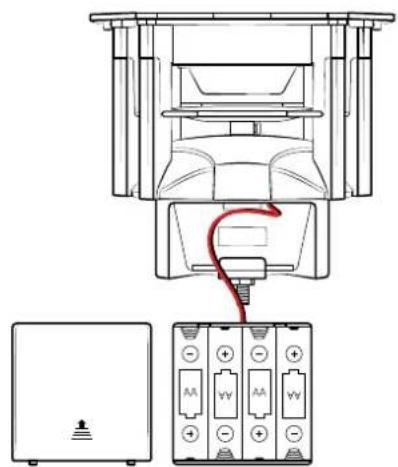
Slide the battery compartment cover (11a) back onto the battery box (11). Place the battery box (11) with the cable connection back into the battery compartment (10) and press the battery box back down into the holder.
06.2 CHANGING BATTERIES
NOTICE
Please note that the timer will retain the set time and programmed feeding times for approximately 1 minute when batteries will be replaced. If you need longer to change the batteries, the time and feeding times must be set again.
CAUTION
If you want to operate the feeder with an optional 6V solar panel, please remove any batteries/rechargeable batteries from the battery box (11) to prevent damage to the timer and the batteries.
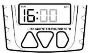
07 | SET THE TIMERS
07.1 SELECT TIME FORMAT
Once the batteries have been inserted correctly, the display will show 00:00.
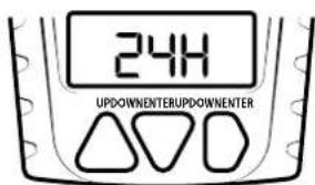
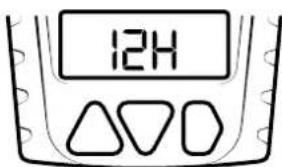
The factory default time format is set to 24 hours. To switch to the 12-hour format, press and hold the ENTER button (09) until 24-h appears on the display.
Then press the UP button (07) or the DOWN button (08) to select the 12-hour format (12-h). Confirm the setting with the ENTER button (09).
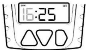
- Press the ENTER button (09). The hour digits will start flashing.
- Set the desired hour using the UP (07) and DOWN (08) buttons.
- Confirm with ENTER (09) to switch to the minute setting.
- The minute digits will now flash. Set the minutes using UP (07) and DOWN (08).
- Press the ENTER button (09) to set working days and feeding times (see section 07.3 below).
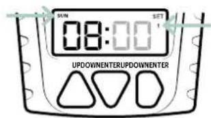
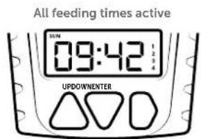
07.3 SETTING WORKING DAYS + FEEDING TIMES
The working days and feeding times are programmed immediately after setting the time. After you have confirmed the minute entry with the ENTER button (09), SUN (English for 'Sunday') flashes in the top left corner of the display. At the same time, the number 1 appears in the top right-hand corner under SET, which stands for the first feeding time.
07.3.1 Enter feeding time 1 for Sunday
- Press the ENTER button (09). The hour digits will start flashing.
- Set the desired hour using the UP (07) and DOWN (08) buttons.
- Confirm with ENTER (09) to switch to the minute setting.
- The minute digits will now flash. Set the minutes using UP (07) and DOWN (08) and confirm again with ENTER (09).
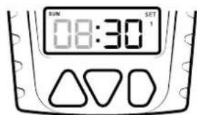
07.3.2 Setting the spreading duration
- After entering the minutes, you will automatically switch to setting the spreading duration (seconds display flashes, factory setting: 7 seconds).
- Use the UP (07) and DOWN (08) buttons to select a duration between 1 and 30 seconds.
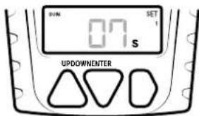
- Press the ENTER button (09) to set the working days.
07.3.3 Setting working days
After setting the spreading time, you will automatically be taken to the selection of weekdays on which the feed spreader should be active according to the programmed feeding time 1. The display now shows all weekdays with their English abbreviations:
| SUN | MON | TUE | WED | THU | FRI | SAT |
| Sunday | Monday | Tuesday | Wednesday | Thursday | Friday | Saturday |
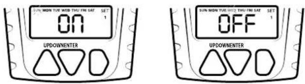
At the start, SUN flashes for Sunday. At the same time, ON appears on the display, which means that feeding time 1 is activated for Sunday.
- To deactivate Sunday, press the UP button (07) or DOWN button (08) until OFF is displayed.
- Press the ENTER button (09) to confirm your selection and move on to the next day.
- For each additional day of the week, use the UP (07) or DOWN (08) button to select between ON (feeding time 1 active) or OFF (feeding time 1 inactive).
- Confirm your selection with the ENTER button (09) to confirm your selection and move on to the next day.
- Proceed in the same way for all remaining days of the week.
Example:
Sunday feeding time 1 active Wednesday feeding time 1 off
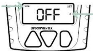
07.3.4 Enter feeding time 2
After confirming the entry of feeding time 1 for the last day SAT (Saturday) with the ENTER button (09), the device automatically switches to feeding time 2. OFF flashes on the display. SUN (Sunday) appears again in the top left corner, and the number 2, which stands for the second feeding time, is displayed on the right.
- Set the desired hour using the UP (07) and DOWN (08) buttons.
- Confirm with ENTER (09) to switch to the minute setting.
- The minute digits will now flash. Set the minutes using UP (07) and DOWN (08) and confirm again with ENTER (09).
- Then set the spreading duration as described in section 07.3.2 and the working days as described in section 07.3.3.
07.3.5 Enter feeding times 3 and 4
To enter feeding times 3 and 4, proceed in the same way as for feeding time 2 (section 07.2.3).
Example:
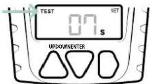
07.4 TEST DURATION
Once feeding time 4 has been set, press the ENTER button (09) to display a 'test duration'. The seconds digits will start flashing on the display and TEST will appear
in the top left corner. Use the UP (07) and DOWN (08) buttons to enter a test duration of 1-30 seconds.
NOTICE
We recommend a maximum test duration of 2 seconds in order to dispense only a small amount of feed for test runs.
Further information on operating the test function can be found in Chapter 08 | TEST FUNCTION
07.5 DEACTIVATING THE TIMERS
To cancel a custom feeding time, press the ENTER button (09) repeatedly until you get to the start time entry in the appropriate timer. Press the UP (07) or DOWN (08) button repeatedly until the display shows OFF. Press the ENTER button (09) to exit programming mode.
Reinstall the housing cover (05) on the feeder housing (01) and screw on the locking screw.
08 | TEST FUNCTION
After installing the feed spreader, this function helps you to determine the optimum time interval, spread amount and spread radius depending on the feed used. The test duration can be set as described in chapter 07.4.

NOTICE
We recommend a maximum test duration of 2 seconds in order to dispense only a small amount of feed for test runs.

ACHTUNG
- Keep a distance of minimum 8m from the feeder for both test and regular operation!
- Protect your eyes and extremities! The fast rotation of the feeding engine and the ejected feed can be harmful.
- ▲ Never reach into the housing and the spinner plat during operation - there is a risk of cut injuries and amputation of fingers!
Not for use in closed rooms!
Press and hold the UP (07) and DOWN (08) buttons simultaneously for approx. 3 seconds and then release them. A 5-second countdown appears on the display. Once the countdown has elapsed, the feed spreader automatically starts the test phase.
To cancel the test, press the ENTER button (09) during the countdown.
09 | CLEANING + STORAGE
Do not clean the device with benzine or harsh cleaning agents. We recommend using a lint-free, slightly damp microfibre cloth to clean the outer parts of the device.
Never immerse the feeder in water for cleaning.
Before cleaning, switch off the device and remove the batteries. When not in use, store the feeder in a dust-free, dry, cool place. The product is not a toy – keep it out of the reach of children. Keep the product away from pets.
10 | TECHNICAL SPECIFICATIONS
| Power supply | 4x AA batteries LR6 1.5V or equivalent rechargeable AA batteries (not included) |
| Feeding times per day | 1 - 4 |
| Spreading range approx. 7 m in 2 m height | |
| Disperse quantity approx. 125 g/1 second | |
| Feeding duration with timer | 1 – 30 seconds |
10.1 MODEL 204370 (WITHOUT CONTAINER)
| Dimensions approx. 14 x 14 x 13,8 cm |
| Weight approx. 450 g |
10.2 MODEL 204371 (WITHCONTAINER)
| Dimensions container approx. 25 x 25 x 40 cm | |
| Capacity container | 20 kg/25 liters (e.g. full grains of corn) |
| Weight approx. 2150 g | |
DÖRR GmbH reserves the right to make technical changes without notice.
11 | SCOPE OF DELIVERY
11.1 MODEL 204370 WITHOUT CONTAINER
1x Feeder
each 4x screws, nuts, washers, self-tapping screws
1x Safety hints
11.2 MODEL 204371 WITH CONTAINER
1x Feeder
1x Collapsible feed container with lid
each 4x screws, nuts, washers, self-tapping screws
1x Safety hints
12 | DISPOSAL, CE MARKING

12.1 DISPOSAL OF BATTERIES/ACCUMULERS
Batteries and rechargeable batteries are marked with the symbol of a crossed-out waste bin. This symbol indicates that empty batteries or rechargeable batteries that can no longer be recharged must not be disposed of in household waste. Old batteries may contain harmful substances that can cause damage to health and the environment. As the end user, you are legally obliged to return used batteries (under German battery law, Section 11 Act Revising the Law of Waste-Related Product Responsibility for Batteries and Accumulators). You can return batteries free of charge after use at the point of sale or in your immediate vicinity (e.g. at municipal collection points or in shops). You can also return batteries to the seller by post.

12.2 WEEE INFORMATION
The WEEE (Waste Electrical and Electronic Equipment) Directive, which came into force as European law on 13 February 2003, led to comprehensive changes in the disposal of discarded electrical equipment. The primary purpose of this directive is to prevent e-waste while promoting reuse, recycling and other forms of reprocessing in order to reduce waste. The WEEE logo (dustbin) shown on the product and on the packaging indicates that the product must not be disposed of in normal household waste. You are responsible for delivering all discarded electrical and electronic equipment to appropriate collection points. Sorting waste for separate collection and sensible recycling of packaging waste helps to use natural resources more sparingly. Furthermore, e-waste recycling is a contribution to preserving our environment and thus also people's health. Further information on the disposal of electrical and electronic equipment, recycling and collection points can be obtained from local authorities, waste disposal companies, specialist retailers and the manufacturer of the device.

12.3 DISPOSAL OF THE PACKAGING
Dispose of the packaging by type. Give cardboard to the waste paper, foils to the collection of recyclables.
√ 12.4 CONFORMITY WITH ROHS
The imprinted CE mark complies with the applicable EU standards and indicates that the device meets the requirements of all EU directives applicable to this product.
FRANÇAIS
natural_image
Cross-sectional diagram of a mechanical piston assembly with internal components and directional arrows (no text or labels)06 | MISE EN SERVICE
06.1 BATTERIEN EINLEGEN
IMPORTANT
natural_image
Cross-sectional diagram of a mechanical assembly with internal components and a red spiral path (no text or labels)
natural_image
Cross-sectional diagram of a mechanical device with internal components and directional arrows (no text or symbols)natural_image
Technical line drawing of a mechanical device with a red cable inserted into a housing (no text or symbols)06.2 REMPLACEMENT DES PILES

REMARQUE
natural_image
Pure diagram of a circular mechanical or electrical component with radial arrows, no text or symbols present.08 | FONCTION TEST
12.4 CONFORMITÉ ROHS
natural_image
Cross-sectional diagram of a mechanical piston assembly with internal components and directional arrows (no text or labels)06 | PUESTA EN MARCHA
natural_image
Cross-sectional diagram of a mechanical assembly with internal components (no text or labels)
natural_image
Cross-sectional diagram of a mechanical assembly with internal components and directional arrows (no text or labels)natural_image
Technical line drawing of a mechanical device with a red cable inserted into a housing (no text or symbols)natural_image
Pure geometric diagram of a square frame with concentric circles and radial arrows, no text or symbols present.natural_image
Cross-sectional diagram of a mechanical piston assembly with internal components and directional arrows (no text or labels)06 | PRIMA ACCENSIONE
06.1 INSERIMENTO DELLE BATTERIE
IMPORTANTE
natural_image
Cross-sectional diagram of a mechanical assembly with internal components and a red spiral path (no text or labels)
natural_image
Cross-sectional diagram of a mechanical assembly with internal components and directional arrows (no text or labels)natural_image
Technical line drawing of a mechanical device with a red cable inserted into a base (no text or symbols)natural_image
Pure geometric diagram of a square frame with concentric circles and radial arrows, no text or symbols present.12.4 CONFORMITÀ ROHS
natural_image
Cross-sectional diagram of a mechanical piston assembly showing internal components and fluid flow direction (no text or labels)06 | PRVNÍ UVEDENÍ DO PROVOZU
06.1 VLOŽENÍ BATERIÍ
! DÜLEŽITÉ
natural_image
Cross-sectional diagram of a mechanical assembly with internal components and a red spiral path (no text or labels)
natural_image
Cross-sectional diagram of a mechanical assembly with no visible text or symbolsnatural_image
Technical line drawing of a mechanical device with a red cable inserted into a housing (no text or symbols)08 | TESTOVACÍ FUNKCE
12.4 KONFORMITA ROHS
13* Quick release-adapter
natural_image
Cross-sectional diagram of an internal combustion engine cylinder (no text or labels)06 | IBRUGTAGNING
06.1 ISÆTNING AF BATTERIER
! VIGTIGT
natural_image
Cross-sectional diagram of a mechanical assembly with internal components and a red spiral path (no text or labels)
natural_image
Cross-sectional diagram of a mechanical assembly with no visible text or symbolsnatural_image
Technical line drawing of a mechanical device with a red cable inserted into a base (no text or symbols)07.3.4 Indtast fodringstid 2
10.1 MODEL 204370 (UDEN BEHOLDER)
| Dimensioner ca. 14 x 14 x 13,8 cm |
| Vægt ca. 450 g |
10.2 MODEL 204371 (MED BEHOLDER)
12 | BORTSKAFFELSE, CE-MÆRKNING
12.1 BORTSKAFFELSE AF BATTERI
7 UP-painike △ (ylös)
8 DOWN-painike ▽ (alas)
natural_image
Cross-sectional diagram of a mechanical piston assembly showing internal components and fluid flow direction (no text or labels)06 | KÄYTTÖÖNOTTO
06.1 PARISTOJEN ASETTAMINEN
! TÄRKEÄÄ
Rehunlevitin'n takana on paristokotelo (10) ja paristolaatikko (11).
natural_image
Cross-sectional diagram of a mechanical assembly with internal components (no text or labels)
natural_image
Cross-sectional diagram of a mechanical assembly with internal components and directional arrows (no text or labels)natural_image
Technical line drawing of a mechanical device with a red cable inserted into a housing (no text or symbols)10 | TEKNISET TIEDOT
natural_image
Cross-sectional diagram of a mechanical piston assembly with internal components and directional arrows (no text or labels)06 | ÜZEMBE HELYEZÉS
06.1 AZ ELEMEK BEHELYEZÉSE
! FONTOS
natural_image
Cross-sectional diagram of a mechanical assembly with internal components and a red spiral path (no text or labels)
natural_image
Cross-sectional diagram of a mechanical assembly with internal components and directional arrows (no text or labels)natural_image
Technical line drawing of a mechanical device with a red cable inserted into a housing (no text or symbols)08 | TESZTFUNKCIÓ
11 | CSOMAG TARTALMA
11.1 MODELL 204370 TARTÁLY NÉLKÜL
02 | BATTERIJ WAARSCHUWINGEN
03 | PRODUCTBESCHRIJVING
natural_image
Cross-sectional diagram of a mechanical piston assembly with internal components and directional arrows (no text or labels)06 | INGEBRUIKNAME
06.1 PLAATSEN VAN DE BATTERIJEN
BELANGRIJK
natural_image
Cross-sectional diagram of a mechanical assembly with internal components and a red spiral path (no text or labels)
natural_image
Cross-sectional diagram of a mechanical assembly with no visible text or symbolsnatural_image
Technical line drawing of a mechanical device with a red cable inserted into a base (no text or symbols)08 | TESTFUNCTIE
12.3 VERPAKKING AFVOEREN
8 DOWN-knapp ▽ (ned)
9 ENTER-knapp D (inmatningsknapp)
10 Batterifack
11 Batterilâda
natural_image
Cross-sectional diagram of a mechanical piston assembly with internal components and directional arrows (no text or labels)06 | IDRIFTTAGANDE
06.1 SÄTTA I BATTERIERNA

VIKTIGT
natural_image
Technical line drawing of a mechanical assembly with two views showing internal components and red flow arrows (no text or symbols)natural_image
Technical line drawing of a mechanical device with a red cable inserted into a base (no text or symbols)07.1 VÄLJA TIDSFORMAT
07.3.4 Ange utfodringstid 2