Smart Home Panel 3 - Electrical panel ECOFLOW - Free user manual and instructions
Find the device manual for free Smart Home Panel 3 ECOFLOW in PDF.

| Product Type | Smart Electrical Panel for Home Energy Management |
| Available Models | 32 circuits (EF-SHP-32) and 24 circuits (EF-SHP-24) |
| Dimensions (32 circuits) | 1 150 × 365 × 188 mm |
| Dimensions (24 circuits) | 1 049 × 365 × 188 mm |
| Weight (32 circuits) | 40.3 ± 0.2 kg |
| Weight (24 circuits) | 28.7 ± 0.2 kg |
| Enclosure Protection | NEMA 3R (rain-resistant) |
| Installation Method | Surface or semi-flush mount |
| Nominal Input Voltage | 120/240 V~ (split phase) or 208 Y/120 V~ (three-phase) |
| Nominal Frequency | 60 Hz |
| Max Grid Current | 160 A (200 A protective device) |
| Branch Circuits (32 circuits) | 8 × 90 A and 24 × 60 A |
| Branch Circuits (24 circuits) | 24 × 60 A |
| Communication Methods | Bluetooth, WLAN, Ethernet, CAN, RS485 |
| Certifications | UL 67, UL 869A, UL 916, UL 1741, CSA C22.2 #29, #205, #107.1 |
| Operating Temperature | -30 to 50 °C |
| Operating Humidity | Up to 100% RH (with condensation) |
| Max Altitude | ≤ 3,000 m |
| Compatible Circuit Breakers | Eaton, Square D, Siemens, ABB (GE) - see manual for specific models |
| Smart Input Box Included | Yes, for connection to EcoFlow storage system |
| Installation Required | By a qualified electrician |
| Warranty | Refer to product documentation |
Frequently Asked Questions - Smart Home Panel 3 ECOFLOW
User questions about Smart Home Panel 3 ECOFLOW
0 question about this device. Answer the ones you know or ask your own.
Ask a new question about this device
Download the instructions for your Electrical panel in PDF format for free! Find your manual Smart Home Panel 3 - ECOFLOW and take your electronic device back in hand. On this page are published all the documents necessary for the use of your device. Smart Home Panel 3 by ECOFLOW.
USER MANUAL Smart Home Panel 3 ECOFLOW
1 Safety Instructions
1 Disclaimer
1 Symbol Conventions
1 Safety Symbols
1 Important Safety Instructions
2 Technical Specifications
2 EcoFlow Smart Home Panel 3 (32 Circuits)
2 EcoFlow Smart Home Panel 3 (24 Circuits)
3 Compliance
3 FCC Compliance Statement
3 Industry Canada Compliance
3 Conformidad con la NOM
4 Unpacking and Preparation
4 What's in the Box
4 Preparing materials and tools
5 Product Overview
6 Installation
6 Cable entry setting
6 Mounting
8 Subpanel setting (Optional)
9 Wiring
10 Communication
11 EcoFlow Smart Inlet Box Installation
11 Pre-Installation: site planning
11 Step 1: Mount the Inlet Box on the wall
12 Step 2: Wiring
13 Step 3: Re-Install the cover of the Inlet Box
13 Step 4: Connect to storage systems
13 Completing installation
15 Reset relays if failure occurs
15 System Commissioning
17 Circuit Breaker Compatibility
17 Main circuit breaker
17 Branch circuit breaker
Table des matières
This product includes essential printed documentation required for setup and basic usage. For detailed manuals, resources, and the most up-to-date information about the product, visit https://www.ecoflow.com/support/download. Fully read and understand the product documentation prior to use. Improper use may result in serious injury, damage, or property loss. By using this product, you agree to and accept all terms outlined in the product documentation. EcoFlow is not liable for losses, damages, or injuries caused by misuse or non-compliance.
Symbol Conventions
The following table describes the symbol conventions used in this document. Please note that all the instructions and cautions on the equipment or in related documents are only supplements to local laws and regulations.
| Symbol | Description |
| Indicates a potentially hazardous situation that, if not avoided, could result in equipment damage, data loss, performance deterioration, or unanticipated results.NOTICE is used to address practices not related to personal injury. | |
 | Indicates additional information that promotes understanding of the product or a topic. |
Safety Symbols
| Symbol Description | |
 | Caution! Risk of Danger1. Disconnect the equipment from all voltage sources before servicing.2. Do not disconnect under load. |
 | Caution! Risk of Electric ShockDo not remove the cover (or back). No user serviceable parts inside. Refer servicing to qualified service personnel. |
 | Refer to DocumentationRead all documentation supplied with the product. |
 | GroundingIndicates the position for connecting the protective earthing (PE) cable. |
Important Safety Instructions

- THE MANUAL, PAMPHLET, OR INSTRUCTION SHEET SHOULD BE CONSULTED BEFORE INSTALLATION OF THE PANELBOARD.
- RISK OF ELECTRIC SHOCK – MORE THAN ONE DISCONNECT SWITCH MAY BE REQUIRED TO DEENERGIZE THE EQUIPMENT BEFORE SERVICING.
• TURNING OFF PARALLEL ENERGY SOURCE DISCONNECT
DOES NOT DEENERGIZE THIS PANEL. TURN OFF POWER FROM ALL SOURCES SUPPLYING THIS EQUIPMENT BEFORE WORKING INSIDE.
- BOTH THE LINE AND LOAD TERMINALS MAY BE ENERGIZED WHEN THE BREAKER IS IN THE OPEN (OFF) POSITION.
General
- Intended use: suitable for use as service equipment (except in Canada).
- These servicing instructions are for use by qualified personnel only. To reduce the risk of electric shock, do not perform any servicing other than that specified in the operating instructions unless you are qualified to do so.
- Please read the product document carefully before installing, operating, or servicing this equipment.
- Installation of this equipment must conform to local standards, national electrical safety standards, and the manufacturer's instructions.
- MORE THAN ONE LIVE CIRCUIT. DISCONNECT ALL SOURCES OF SUPPLY BEFORE SERVICING.
- There is a high possibility of electric shock or serious burns due to the high voltages in the equipment.
Operation
- Use appropriate personal protective equipment (PPE) and follow safe electrical work practices.
- Wiring methods in accordance with the National Electrical Code, ANSI/NFPA 70 are to be used.
- Risk of Electric Shock: Do not touch exposed electrical cables or parts with bare hands.
- Be cautious to prevent injury when moving heavy objects.
- Do not install or operate the equipment in an area where flammable or explosive materials are stored.
- Inspect the equipment and cables for damage before installing. Do not install the equipment or cables if damaged in any way.
- Turn off all power supplying this equipment before installation. Disconnect each circuit individually before servicing. AC voltage sources are terminated inside this equipment.
- Always use a properly rated voltage sensing device to confirm power is off.
- During the drilling process, cover the interior equipment to prevent debris from falling into the equipment, and clear the debris after drilling to prevent interference with the equipment.
- Do not damage, smear or cover any warning labels on the device. All labels must be visible after installation.
- Before operating the equipment, check the electrical connections to ensure that the equipment is reliably and permanently grounded.
- Do not place any kind of objects on top of the product during operation.
- To completely de-energize the product, you MUST open the upstream breakers as well as physically unplug all batteries or power. Failure to do so may present a shock hazard.
- Do not place or install flammable or potentially explosive objects near the product or in explosive atmospheres.
- Do not insert foreign objects into any part of the equipment.
- Do not connect life-support systems, other medical equipment, or any other use whereproduct failure could lead to injury to persons or loss of life to circuits which can be remotely switched.
- Replace all devices, doors, and covers before turning on power to this equipment.
- In the case of cables damaged, it must be replaced by the manufacturer, customer service or qualified personnel to
prevent a safety hazard.
- Do not use solvents to clean the equipment.
- Do not use parts or accessories other than those specified for use with the equipment.
- When installing the equipment, the screws need to be tightened according to the specification torque using a special tool.
Environment
- Do not install or operate the equipment in extreme weather events such as lightning, snow, heavy rain, strong wind and so on.
- Install the equipment in a location that prevents damage from flooding. Ensure that no water sources are above or near the equipment, including down spouts, sprinklers, or faucets.
- The equipment must be disposed of according to local codes and regulations.
- Keep out of reach of children or animals.
- This product is designed for residential use only.
Technical Specifications
EcoFlow Smart Home Panel 3 (32 Circuits)
| General | |
| Model | EF-SHP-32 |
| Dimensions | 1150 × 365 × 188 mm(45.28 × 14.37 × 7.40 in) |
| Net Weight | 88.8 ± 0.4 lb (40.3 ± 0.2 kg) |
| Enclosure Protection | NEMA 3R, Rainproof |
| Installation Method | Surface or semi-flush mounting |
| Number of Load Branch Circuit | 90 A × 8, 60 A × 24 |
| System Electrical Parameter | |
| Grid Connection | L1/L2/N/GND |
| Rated Input Voltage | 120/240 V~ (split phase)208Y/120 V~, 3 W (from 3∅ 4 W) |
| Rated Frequency | 60 Hz |
| Max. Continuous Current for Grid Lugs | 160 A |
| Max. Continuous Current for Battery Box Lugs | 150 A |
| Grid Rating | Max. Continuous Current 160 A(OCPD 200 A) |
| Branch Circuit Rating | Max. Continuous Current 90 A (OCPD 125 A)Max. Continuous Current 60 A (OCPD 80 A) |
| Busbar Rating | 200 A |
| Maximum Input Short-circuit Current | 22 kA rms |
| Communication Method | Bluetooth, WLAN, Ethernet, CAN, RS485 |
| Certificates | UL 67, UL 869A, UL 916, UL 1741, CSA Std C22.2 # 29, CSA Std C22.2 # 205, CSA Std C22.22 # 107.1 |
| Environment | |
| Operating Temperature | -22°F to 122°F (-30°C to 50°C) |
| Storage Temperature | -22°F to 122°F (-30°C to 50°C) |
| Operating Humidity | Up to 100% RH, condensing |
| Maximum Operating Altitude | ≤ 9,842 ft (3,000 m) |
EcoFlow Smart Home Panel 3 (24 Circuits)
| General | |
| Model | EF-SHP-24 |
| Dimensions | 1049 × 365 × 188 mm(41.28 × 14.37 × 7.40 in) |
| Net Weight | 63.3 ± 0.4 lb (28.7 ± 0.2 kg) |
| Enclosure Protection | NEMA 3R, Rainproof |
| Installation Method | Surface or semi-flush mounting |
| Number of Load Branch Circuit | 60 A × 24 |
| System Electrical Parameter | |
| Grid Connection | L1/L2/N/GND |
| Rated Input Voltage | 120/240 V~ (split phase)208Y/120 V~, 3 W (from 3∅ 4 W) |
| Rated Frequency | 60 Hz |
| Max. Continuous Current for Grid Lugs | 160 A |
| Max. Continuous Current for Battery Box Lugs | 150 A |
| Grid Rating | Max. Continuous Current 160 A(OCPD 200 A) |
| Branch Circuit Rating | Max. Continuous Current 60 A (OCPD 80A) |
| Busbar Rating | 160 A |
| Maximum Input Short-circuit Current | 22 kA rms |
| Communication Method | Bluetooth, WLAN, Ethernet, CAN, RS485 |
| Certificates | UL 67, UL 869A, UL 916, UL 1741, CSA Std C22.2 # 29, CSA Std C22.2 # 205, CSA Std C22.22 # 107.1 |
| Environment | |
| Operating Temperature | -22°F to 122°F (-30°C to 50°C) |
| Storage Temperature | -22°F to 122°F (-30°C to 50°C) |
| Operating Humidity | Up to 100% RH, condensing |
| Maximum Operating Altitude | ≤ 9,842 ft (3,000 m) |
Compliance
FCC Compliance Statement
Any Changes or modifications not expressly approved by the party responsible for compliance could void the user's authority to operate the equipment.
This device complies with part 15 of the FCC Rules. Operation is subject to the following two conditions:
(1) This device may not cause harmful interference, and
(2) this device must accept any interference received, including interference that may cause undesired operation.
This equipment has been tested and found to comply with the limits for a Class B digital device, pursuant to Part 15 of the FCC Rules. These limits are designed to provide reasonable protection against harmful interference in a residential installation. This equipment generates uses and can radiate radio frequency energy and, if not installed and used in accordance with the instructions, may cause harmful interference to radio communications. However, there is no guarantee that interference will not occur in a particular installation. If this equipment does cause harmful interference to radio or television reception, which can be determined by turning the equipment off and on, the user is encouraged to try to correct the interference by one of the following measures:
- Reorient or relocate the receiving antenna.
- Increase the separation between the equipment and receiver.
- Connect the equipment into an outlet on a circuit different from that to which the receiver is connected.
- Consult the dealer or an experienced radio/TV technician for help.
RF exposure statement
This equipment complies with FCC radiation exposure limits set forth for an uncontrolled environment.
This equipment should be installed and operated with a minimum distance of 20 cm between the radiator and your body.
Industry Canada Compliance
This device complies with Industry Canada's licence-exempt RSSs.
Operation is subject to the following two conditions:
(1) This device may not cause interference, and
(2) This device must accept any interference, including interference that may cause undesired operation of the device.
This Class B digital apparatus complies with Canadian ICES-003.
This transmitter must not be co-located or operating in conjunction with any other antenna or transmitter. This equipment shall be installed and operated with a minimum distance of 20 centimeters between the radiator and your body.
Unpacking and Preparation
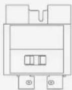
I What's in the Box

natural_image
Blank white rectangular panel with a small black symbol on the top left corner (no text or labels)EcoFlow Smart Home Panel 3 (32 Circuits / 24 Circuits) (the door and deadfront cover packaged separately)
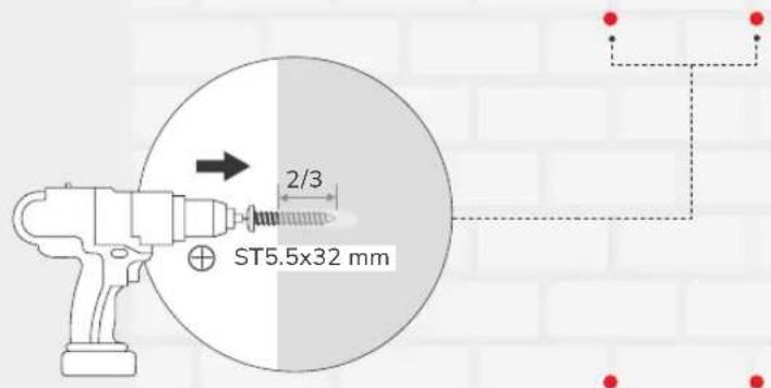
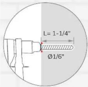
Mark-off template Screws ST5.5x32 mm (x9)

Breaker hold-down (×4)
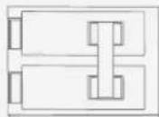
EcoFlow Smart Inlet Box (Smart Home Panel 2 Upgrade) (x1)
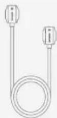
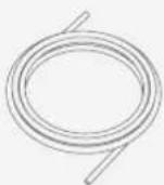
EcoFlow Smart Inlet Box Connection Cable (5P8 Port to 5P8 Port) (x1)

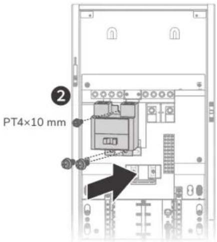
Screws M3×8 mm (×10) Screw PT4×10 mm (×1)

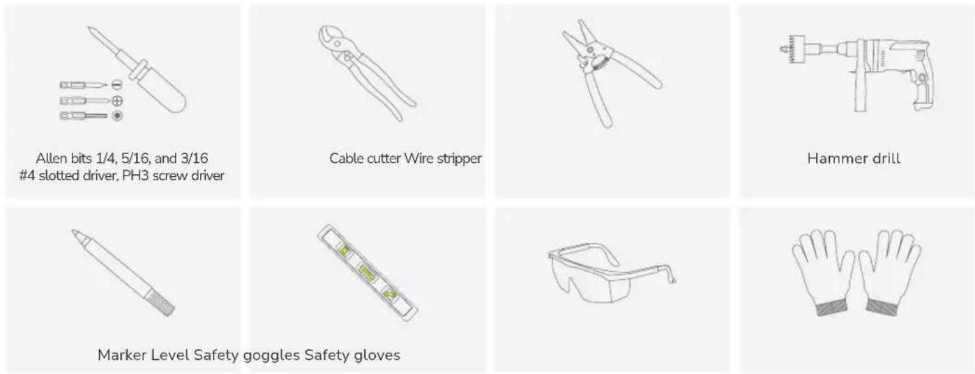
I Preparing materials and tools
- Materials
Main circuit breaker: 100-200A *See "Circuit Breaker Compatibility" for details.
Branch circuit breaker: 125A Max, AFCI/GFCI supported, plug-in type *See "Circuit Breaker Compatibility" for details.
Conductors for grid supply, backup power and loads, copper or aluminum, rated to a minimum of 75^ C ( 165^ F). For branch breakers greater than 80A: rated to minimum of 90^ C ( 194^ F).
*See "Wiring" to check the wire specification.
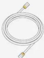
Cable for Ethernet and the smart inlet box communication: CAT6, T568B straight-through, shielded, marked as STP or SFTP
• Standard installation tools
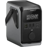
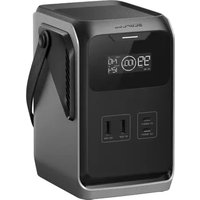
Product Overview
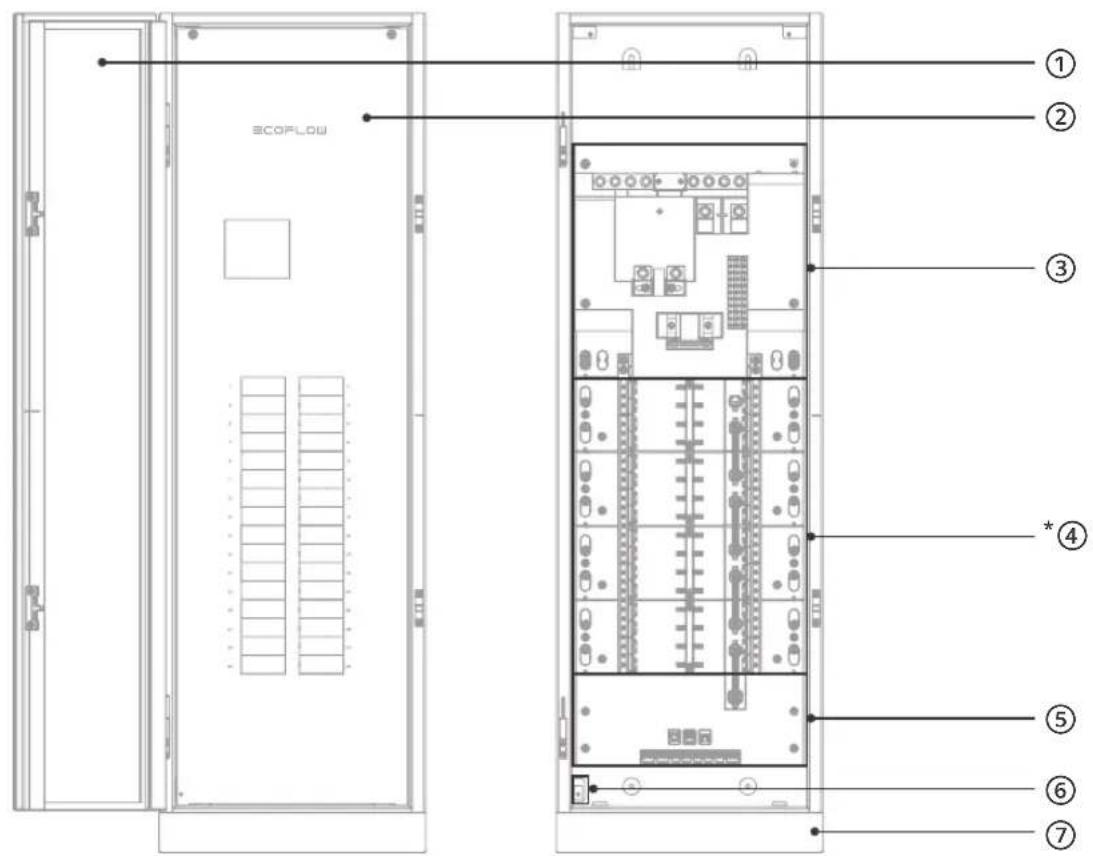
① Door
⑤ Communication module
② Deadfront cover
⑥ Deadfront detection
③ Main circuit breaker module
⑦ Antenna
④ Branch circuit breaker module
*Compared to EcoFlow Smart Home Panel 3 (24 Circuits), EcoFlow Smart Home Panel 3 (32 Circuits) includes an additional 100 A smart module.
Installation
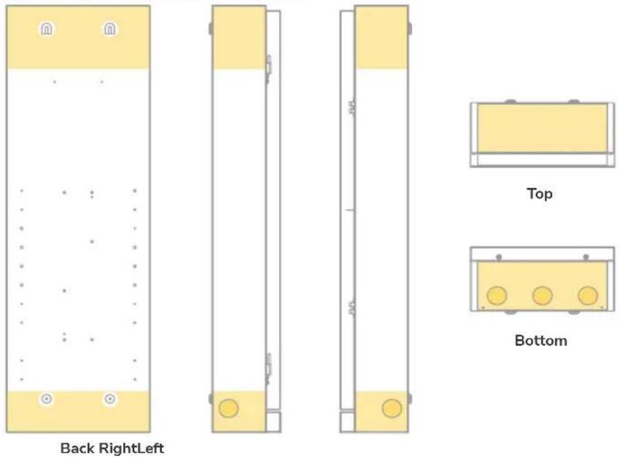
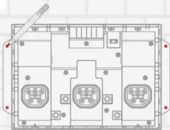
I Cable entry setting
5 preset expandable knockouts: 1-3/4" knockouts
If you need to drill more cable entries, cover the interior equipment to prevent debris from falling into the equipment. Clear the debris after drilling to prevent interference with the equipment. A hydraulic hole puncher is recommended.
After removing knockouts, it's crucial to address the sharp edges to prevent damage to the cable sheaths. You can achieve this by either smoothing the edges with a file or deburring tool or by using cable sheaths or bushings to protect the wires as they pass through.
Allowable entry locations are the yellow highlighted area below.
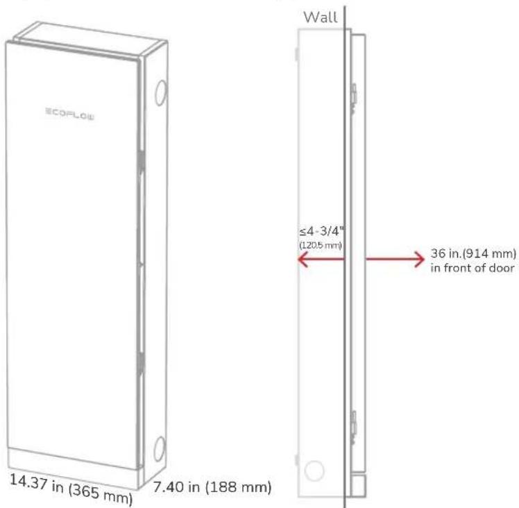
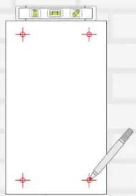
I Mounting
The panel supports surface or semi-flush mounting.
- Clearance
Keep 1.5 inches from the door swing side to ensure the panel door can open to 90°. In case of semi-flush mouting, the depth of recessing the product into the wall must not exceed 4-3/4" (120.5 mm). Otherwise, it limits the access of the panel.
The installation height of the panel should comply with local regulations.
Other equipment that is associated with the electrical installation and is located above or below the electrical equipment shall be permitted to extend not more than 6 in. (150 mm) beyond the front of the electrical equipment.
24 circuits: 41.28 in (1049 mm)
32 circuits: 45.28 in (1150 mm)
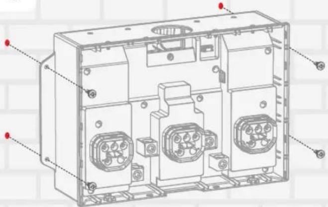
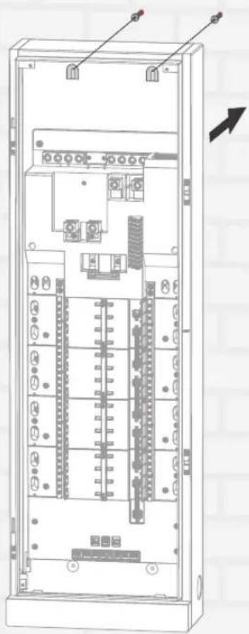
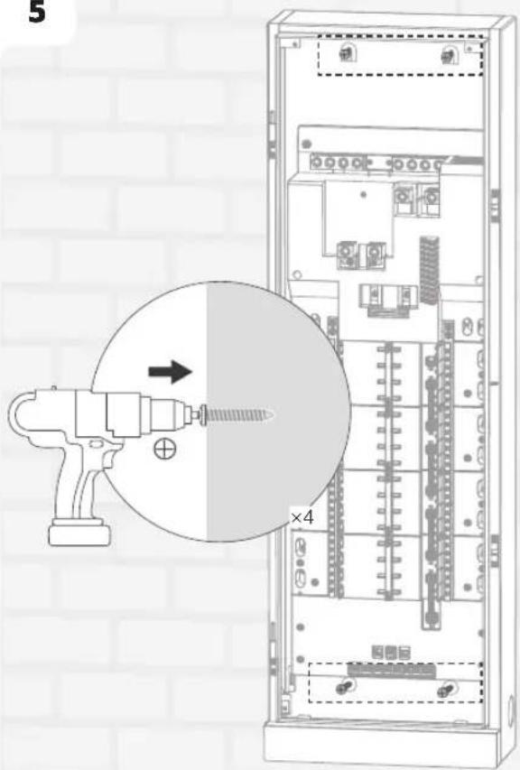
- Mounting the panel
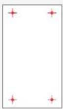
Mark and pre-install four screws into the wall, leaving approximately 1/3 of each screw exposed. Then, mount the panel onto the screws and fully tighten all four screws to secure it.
1
2


3
4

natural_image
Technical line drawing of an electrical enclosure with internal components and wiring (no text or symbols)5

- Mounting the breakers
Use conductive paste on the lower terminal of the MCCB, and the parameters of the conductive paste should be as follows: Contact resistance stability coefficient >0.8, temperature range: -22°F to 221°F (-30°C to 105°C)
-Main circuit breaker
-Branch circuit breaker
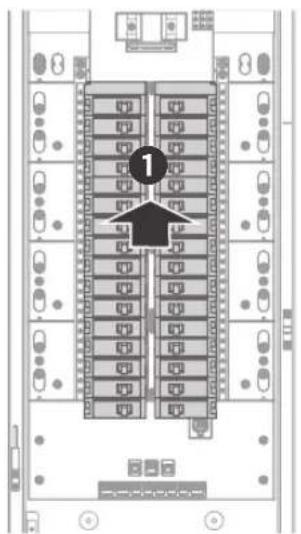
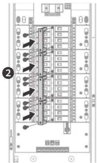

For EcoFlow Smart Home Panel 3 (32 Circuits):
- The 100 A smart module shall be installed at the lowest part of the panel.
- The maximum continuous current rating of each branch circuit of the 100 A smart module is 90 A.
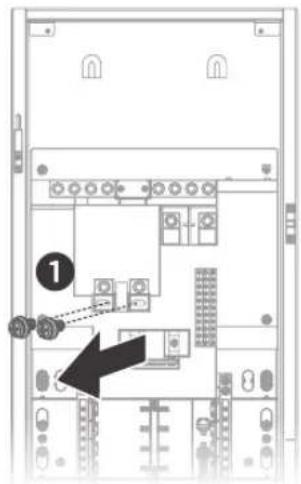
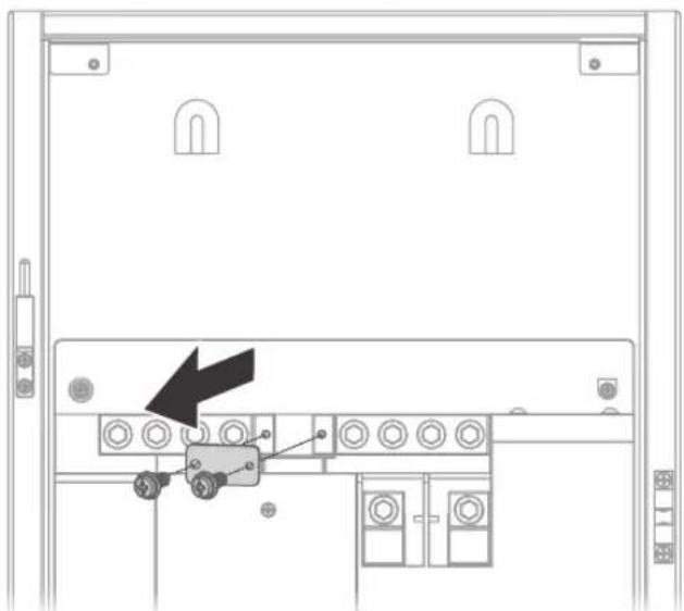
I Subpanel setting (Optional)
When used as a subpanel, unscrew the bonding between neutral and ground.
natural_image
Technical diagram of a server rack with a black arrow pointing to a component (no text or symbols present)I Wiring

Risk of electric shock. Before wiring, make sure the power is off. Ensure that main and branch circuit breakers are in the OFF position.
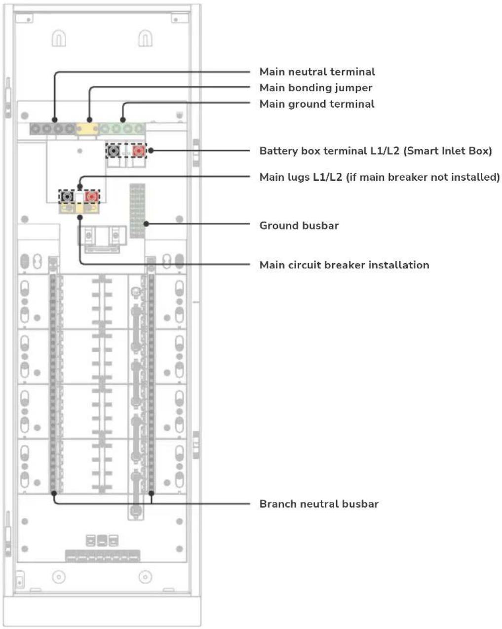
| Terminal Wire Gauge Wire Strip Length Tool Size Torque | ||||
| Main lugs (L1, L2) | Copper wire: ≥ 3/0 AWGAluminum wire: ≥ 250 kcmil | 0.75 inch (20 mm) 5/16 in hex | 275 in-lbs (31.1 N·m) for 3/0AWG - 250 kcmil110 in-lbs (12.4 N·m) for 6AWG - 2/0AWG | |
| Battery box terminal | Copper wire: ≥ 1/0 AWGAluminum wire: ≥ 3/0 AWG | 0.75 inch (20 mm) 5/16 in hex | 275 in-lbs (31.1 N·m) for 3/0AWG - 250 kcmil110 in-lbs (12.4 N·m) for 6AWG - 2/0AWG | |
| Main neutral terminal | 6AWG - 250 kcmil 0.85 inch | (22 mm) 5/16 in hex | 275 in-lbs (31.1 N·m) for 3/0AWG - 250 kcmil110 in-lbs (12.4 N·m) for 6AWG - 2/0AWG | |
| Main ground terminal | 6AWG - 250 kcmil 0.85 inch | (22 mm) 5/16 in hex | 275 in-lbs (31.1 N·m) for 3/0AWG - 250 kcmil110 in-lbs (12.4 N·m) for 6AWG - 2/0AWG | |
| Branch neutral busbar | 14AWG - 4AWG 0.35 inch (9 mm) | 3/16 in slotted 26 in-lbs (2.9 N·m) | ||
| Ground busbar | 14AWG - 4AWG 0.35 inch (9 mm) | 3/16 in slotted 26 in-lbs (2.9 N·m) | ||

For circuit breaker wiring requirements, refer to the instructions on the circuit breakers.
I Communication
- Communication port definition
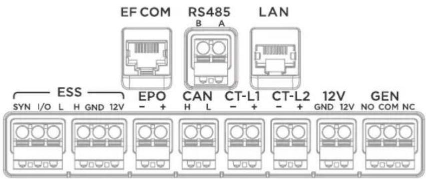
| Communication Port Description | |
| EF COM Connects with EcoFlow Smart Inlet Box | |
| RS485 Reserved communication port | |
| LAN | Ethenet connection |
| ESS Reserved | |
| EPO | This port is shorted by a jumper before the product leaves the factory. If you need to connect the EPO, first remove the jumper, then connect the EPO in accordance with local regulations. |
| CAN | Reserved communication port for connecting with EcoFlow EV charger or for parallel connection of the panel |
| CT-L1 Connects with CT | |
| CT-L2 Connects with CT | |
| 12V Reserved DC 12V power output port | |
| GEN Reserved | |
EcoFlow Smart Inlet Box Installation

Mounting the smart inlet box upside down is not recommended.
I Pre-Installation: site planning
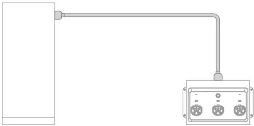
natural_image
Pure electrical circuit lines without any symbolsEnclosure NEMA 3R
Install the panel indoors or outdoors
Enclosure NEMA 1
Install the box indoors and avoid water
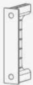
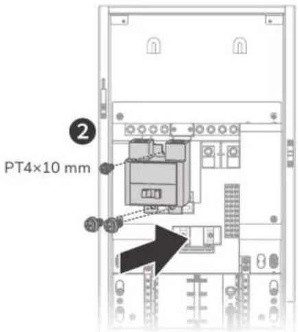
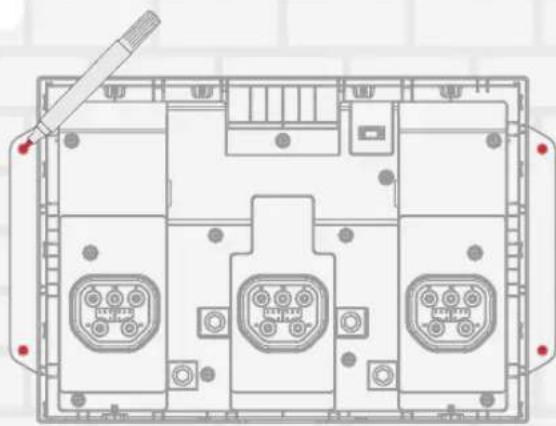
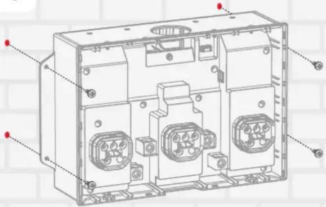
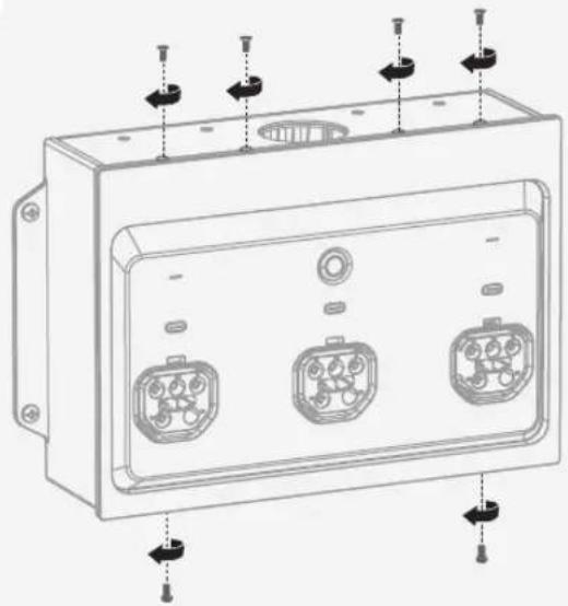
I Step 1: Mount the Inlet Box on the wall
1
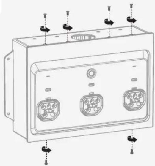
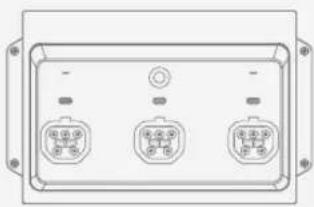
natural_image
Technical line drawing of a rectangular electronic device with three internal connectors and mounting holes (no text or symbols)2
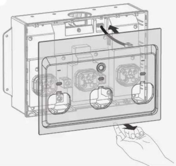
natural_image
Technical line drawing of an open electrical enclosure with internal components and a hand holding the base panel (no text or symbols present)3
natural_image
Top-down schematic of a device layout with labeled ports and connectors (no text or symbols)4
I Step 2: Wiring

- Risk of electric shock. Before wiring, make sure the power is off.
• Install Overcurrent Protection Devices (OCPD) between the box and battery storage, according to the local regulation.
General terminal information is listed below:
| Terminal *Wire gauge Wire strip length Torque Tool | ||||
| L1, L2, N, GND on the smart inlet box | Copper wire: ≥ 1/0 AWGAluminum wire: ≥ 3/0 AWG | 20 mm (13/16 in.) | 110 in-lbs (12.4 N·m) for 6 AWG-2/0 AWG275 in-lbs (31.1 N·m) for 3/0 AWG-250 kcmil | 5/16-inch hex |
*Cable selection in this table is based on a default current of 150 A.
The maximum length bewtween the smart inlet box and the panel is 30 m (98 ft).
The following illustration is an example of using the product as the main panel and connecting with Battery Box (Smart Inlet Box)
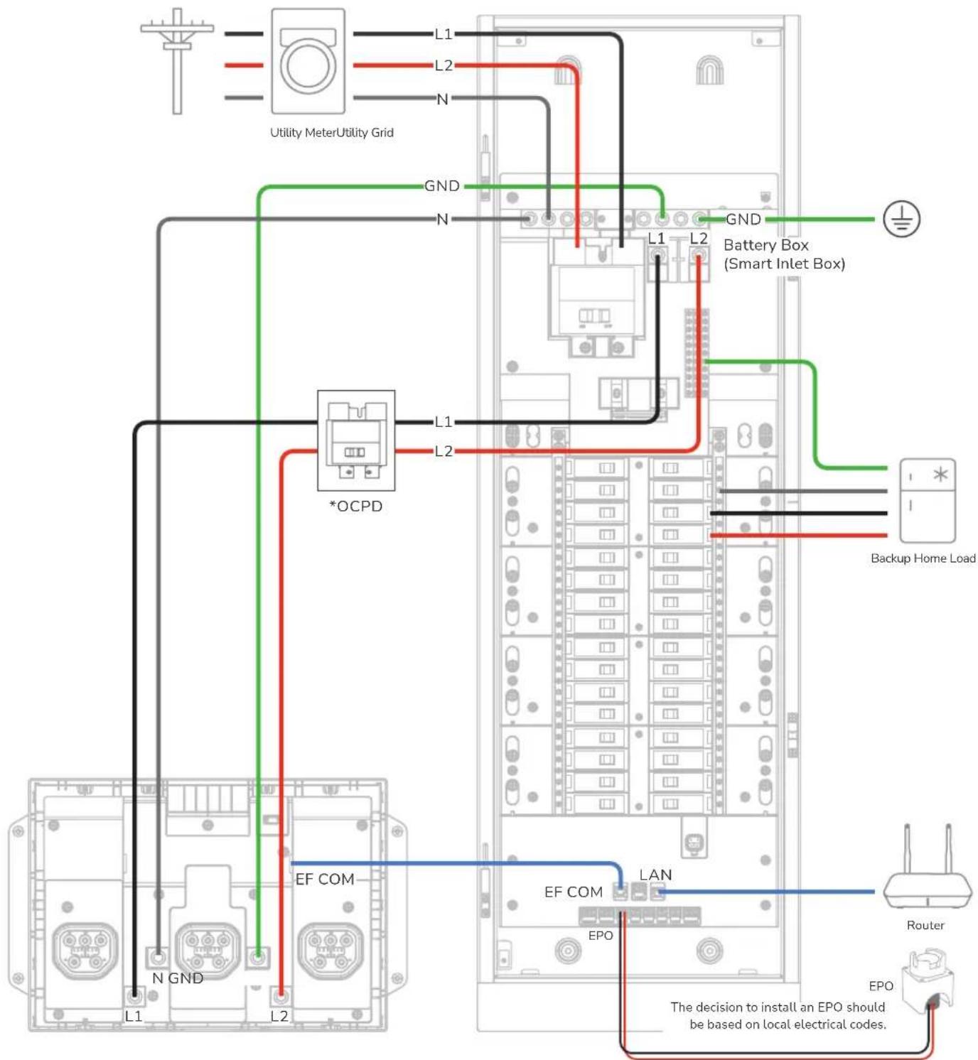
*The OCPD rating must comply with local electrical codes. A 200A, 2P circuit breaker is recommended, with cables sized at a minimum of 3/0 AWG (copper) or 250 kcmil (aluminum).
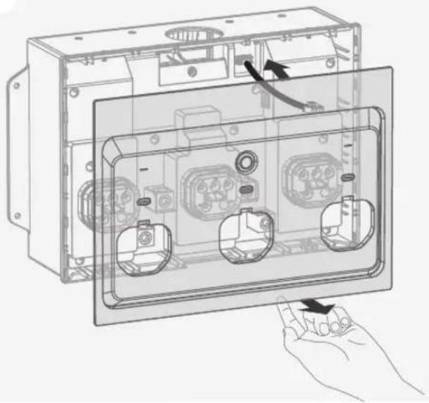
I Step 3: Re-Install the cover of the Inlet Box
1
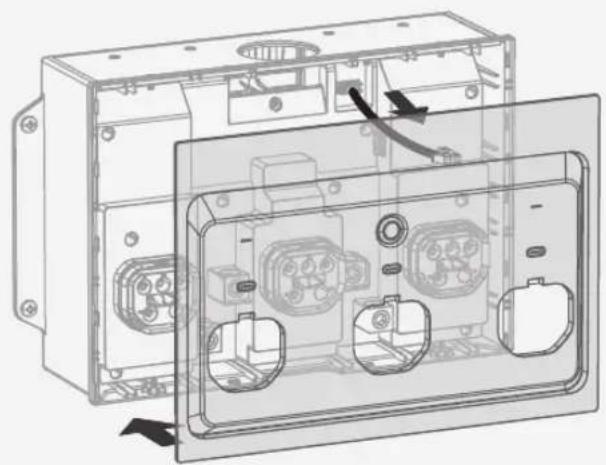
natural_image
Technical line drawing of an open electrical enclosure with internal components and wiring (no text or symbols)2

natural_image
Technical line drawing of a rectangular electronic device with three internal connectors and mounting holes (no text or symbols)I Step 4: Connect to storage systems

If required by local electrical codes, install an overcurrent protection device (OCPD) between the box and the battery storage.
For EcoFlow DELTA Pro Ultra (max. 3 units) / EcoFlow DELTA Pro Ultra X (max. 3 units)
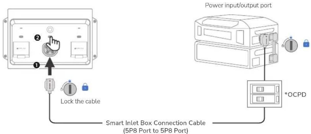
*The OCPD rating must comply with local regulations. A 70A 2P circuit breaker is recommended.
I Completing installation
- Check the connection.
☐ Confirm that all connections are correct, properly grounded, and secure.
☐ Confirm that all screws are tightened.
☐ Use a multimeter in continuity setting to make sure that the hot wire is not short circuited to neutral.
☐ Use a multimeter in continuity setting to make sure that the hot wire is not short circuited to ground.
- Remove twist-outs for the main circuit breaker and branch circuit breaker on the deadfront cover.
Fill any unused open spaces on the cover with standard metal or plastic filler plate.
- Install the deadfront cover.
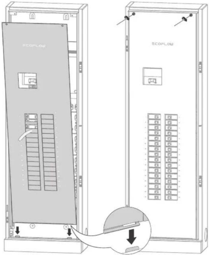
- Install the door.
Then, slide down the glass door onto the hinges. Lock the panel if necessary.
- Energize the panel.
Before energizing, ensure that main and branch circuit breakers are in the OFF position. To energize, first turn ON the main breaker, and then turn ON each branch circuit breaker. Check the indicators of the smart inlet box to ensure the system operates properly. If the error icon exists, check the EcoFlow app for troubleshooting.
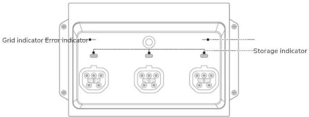
| Indicator Status Description | |||
| GRID | ○ | Solid white Grid voltage is detected | |
| ● | Blinking red Grid overvoltage or overfrequency | ||
| ● | Solid red Grid voltage is not detected | ||
| AC1/AC2/AC3(Storage) | ● | Solid green Powering your home appliances | |
| ● | Breathing green Standby | ||
| ● | Solid yellow Charging | ||
| ● | Blinking red | Error | |
| ● | Solid red | ||
| ERROR | ● | Solid red System error | |
| ● | Off No system error | ||
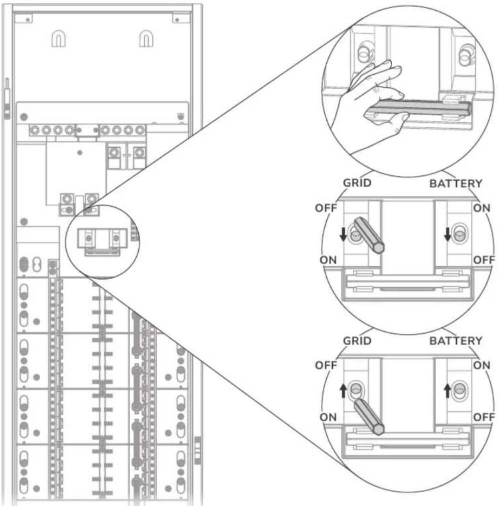
I Reset relays if failure occurs
When the EcoFlow app prompts a main relay fault (fault code: 2005), perform the following operations.
System Commissioning
1 Download and install EcoFlow App
Scan the QR code or download at: https://download.ecoflow.com/app


2 Create account and log in
After the account is created, enter the account and password.


3 Add system and set up Internet
Add the portable power station and smart home panel 3 manually or using Bluetooth.
• Via Wi-Fi
Select WiFi select the appropriate network and enter the password.
• Via Ethernet
Connect the system to a router using a network cable in the DHCP or Static mode.
- In the default DHCP mode, the device obtains IP address automatically (recommended).
- In the Static mode, network administrator (homeowner) should set a valid IP address to the device. To avoid IP address conflict, check the IP addresses of other devices on the network by accessing router's settings.


4 Commissioning
There are 5 steps for commissioning. Steps 1-4 are shown below, and step 5 is setting check. Settings include home location, grid voltage and frequency, current of the main circuit, split-phase circuits, the maximum circuit current of each circuit.


5 Check the firmware for update
After configuring and entering the system main page, check for the latest firmware update. If any, make sure the firmware is up to date.
6 Validate app control
Check whether the EcoFlow app can control the system properly, or whether the operation mode can be switched.
Circuit Breaker Compatibility
NOTICE
This product has been evaluated for use with the branch circuit breaker types listed below in accordance with the UL Standard for Panelboards.
I Main circuit breaker
| Brand Model Rated Current | ||
| EATON CSR 100-200A |
I Branch circuit breaker
- Eaton
| Type Amp Catalog Number Pole | |||
| General circuit breakers type BR | 32 circuits: 10-125 32 circuits: BR or BRH; followed by 110 to 2125 | 1-pole and 2-pole | |
| 24 circuits: 10-80 24 circuits: BR or BRH; followed by 110 to 280 | |||
| Duplex (tandem) circuit breakers type BD 10-50 BD followed by 1010 to 5050 1-pole | |||
| Quadplex (tandem) circuit breakers type BQ and BQC | 15-50 BQ followed by 215215 to 2502120 | 1-pole and 2-pole | |
| Combination arc fault circuit interrupter circuit breakers type BR | 10-20 | BRC, BRN or BRL followed by 110 to 120; followed by AF or CAF (pigtail only) | 1-pole and 2-pole |
| Ground fault circuit interrupter circuit breakers type GFTCB and GFEP | 10-60 | BRN, GFTCB, BRHN, or GFTCBH followed by 110 to 260; may be followed by GF (pigtail only) | 1-pole and 2-pole |
| Ground fault equipment protection circuit breakers type GFEP | 15-50 | BRN or GFEP followed by 115 to 250; may be followed by EP (pigtail only) | 1-pole and 2-pole |
| Dual function combination ground fault and arc-fault protection circuit breakers type BR | 10-20 | BRN or BRAFGF followed by 110 to 120; may be followed by DF (pigtail only) | 1-pole |
- Square D
| Type Amp Catalog Number Pole | |||
| General circuit breakers type HOM | 32 circuits: 10-125 32 circuits: HOM followed by 110 to 2125 | 1-pole and 2-pole | |
| 24 circuits: 10-80 24 circuits: HOM followed by 110 to 280 | |||
| Tandem circuit breakers type HOMT | 10-30 | HOMT followed by 1010 to 3020 | 1-pole |
| Quad tandem circuit breakers type HOMT | 15-50 HOMT followed by 1515215 to 2020250 | 1-pole and 2-pole | |
| Quad tandem circuit breakers type HOMT | 15-50 | followed by 110 to 220; may be followed by P; followed by CAFI | 2-pole |
| Combination arc-fault circuit interrupter circuit breakers type HOM-CAFI | 10-20 | HOM followed by 110 to 220; may be followed by P; followed by CAFI | 1-pole and 2-pole |
| Ground fault circuit interrupter circuit breakers type HOM-GFI | 10-50 | HOM followed by 110 to 250; may be followed by P; followed by GFI | 1-pole and 2-pole |
| Ground fault equipment protection circuit breakers type HOM-EPD | 15-50 HOM followed by 15 to 250; followed by EPD | 1-pole and 2-pole | |
| Dual function combination ground fault and arc-fault protection circuit breakers type HOM-DF | 10-20 | HOM followed by 110 to 120; may be followed by P; followed by DF | 1-pole |
- Siemens
| Type Amp Catalog Number Pole | |||
| General circuit breakers type QP | 32 circuits: 10-125 | 32 circuits: Q followed by 110 to 2125; may be followed by H | 1-pole and 2-pole |
| 24 circuits: 10-80 | 24 circuits: Q followed by 110 to 280; may be followed by H | ||
| Duplex (tandem) circuit breakers type QT 10-30 | Q followed by 1010 to 3030 | may be followed by NC 1-pole | |
| Triplex (tandem) circuit breakers type QT 10-30 | Q followed by 21010 to 230 | 30; followed by CT | 1-pole and 2-pole |
| Quadplex (tandem) circuit breakers type QT 15-40 | Q followed by 21515 to 240 | 4040; followed by CT2 2-pole | |
| Branch-feeder arc-fault circuit interrupter circuit breakers type QAF2 | 15-20 | QA followed by 115 to 120; followed by AF; may be followed by H (pigtail only) | 1-pole and 2-pole |
| Combination arc-fault circuit interrupter circuit breakers type QAF and QAF2 | 10-20 | Q or QA followed by 115 to 120; followed by AFC; may be followed by H (pigtail only) | 1-pole and 2-pole |
| Tandem combination arc-fault circuit interrupter circuit breakers type CAFCI | 10-20 | Q followed by 1010 to 2020; followed by AFC (pigtail only) | 1-pole |
| Ground fault circuit interrupter circuit breakers type QPF and QPF2 | 10-60 | QF followed by 110 to 260; followed by A; may be followed by H (pigtail only) | 1-pole and 2-pole |
| Ground fault equipment protection circuit breakers type QE | 15-60 | QE followed by 115 to 260; may be followed by H (pigtail only) | 1-pole and 2-pole |
| Dual function combination ground fault and arc-fault protection circuit breakers type QFGA2 | 10-20 | Q followed by 110 to 120; followed by DF; may be followed by H (pigtail only) | 1-pole |
• ABB (GE)
| Type Amp Catalog Number Pole | |||
| General circuit breakers type THQL, THHQL | 32 circuits: 15-125 32 circuits: THQL followed by 1115 to 2125 | 1-pole and 2-pole | |
| 24 circuits: 15-80 24 circuits: THQL followed by 1115 to 280 | |||
| Ground fault circuit interrupter circuit breakers type THQL, THHQL | 15-50 | THQL or THHQL followed by 1115 to 2150, followed by GFT (pigtail only) | 1-pole and 2-pole |
| Combination arc-fault circuit interrupter circuit breakers type THQL | 15-20 Followed by AF (pigtail only) | 1-pole and 2-pole | |
| Dual function combination ground fault and arcfault protection breakers type THQL,THHQL | 15-20 | THQL or THHQL followed by 1115 to 1120, Followed by DF, (pigtail only) | 1-pole |

When selecting a circuit breaker, the effect of ambient temperature on its rated current must be considered. Circuit breakers are typically rated based on a standard reference temperature (e.g., 40^ C). If the actual installation environment exceeds this temperature, derating is required. Refer to the manufacturer's temperature derating curve for specific adjustment requirements.
natural_image
Blank white rectangular panel with a small black symbol on the top left corner (no text or labels)Panneau EcoFlow Smart Home 3 (32 circuits 24 circuits)
natural_image
Front view of a three-pin electronic device enclosure with indicator lights (no text or symbols visible)2
3

4
natural_image
Technical line drawing of an electrical enclosure with internal components and wiring (no text or symbols)5


natural_image
Technical diagram of a mechanical assembly with labeled components and an arrow indicating a specific part (no text or symbols present)I Câblage

natural_image
Pure electrical circuit lines without any symbolsnatural_image
Technical line drawing of a rectangular electronic device with three internal connectors and mounting points (no text or symbols)2
natural_image
Technical line drawing of an open electrical enclosure with internal components and a hand holding the interior panel (no text or symbols present)3
natural_image
Top-down schematic of an electronic device casing with multiple ports and connectors (no text or labels)4
natural_image
Technical line drawing of an electrical enclosure with multiple terminal blocks and mounting holes (no text or labels)I Étape 2 : Câblage

natural_image
Technical line drawing of an open electrical enclosure with internal components and wiring (no text or symbols)2
natural_image
Technical line drawing of a rectangular electronic device with three internal connectors and mounting holes (no text or symbols)


4 Mise en service