Basa 4.0 - Saw SCHEPPACH - Free user manual and instructions
Find the device manual for free Basa 4.0 SCHEPPACH in PDF.


User questions about Basa 4.0 SCHEPPACH
0 question about this device. Answer the ones you know or ask your own.
Ask a new question about this device
Download the instructions for your Saw in PDF format for free! Find your manual Basa 4.0 - SCHEPPACH and take your electronic device back in hand. On this page are published all the documents necessary for the use of your device. Basa 4.0 by SCHEPPACH.
USER MANUAL Basa 4.0 SCHEPPACH
natural_image
Industrial machine labeled 'Scheppaeh Basa 4.0' with no visible text or symbols on the device itself.| D | BandsägeOriginal-Anleitung | 4 |
| GB | Band SawTranslation from the original instruction manual | 10 |
| FR | Scie à RubanTraduction du manuel d'origine | 16 |
natural_image
Close-up of a mechanical component with a labeled section A, showing a wheel and gear assembly (no text or symbols beyond label)Fig. 4

text_image
A B CFig. 5
natural_image
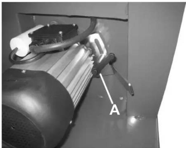
Mechanical assembly diagram showing a rotating frame with labeled point A (no text or symbols beyond label)Fig. 6
text_image
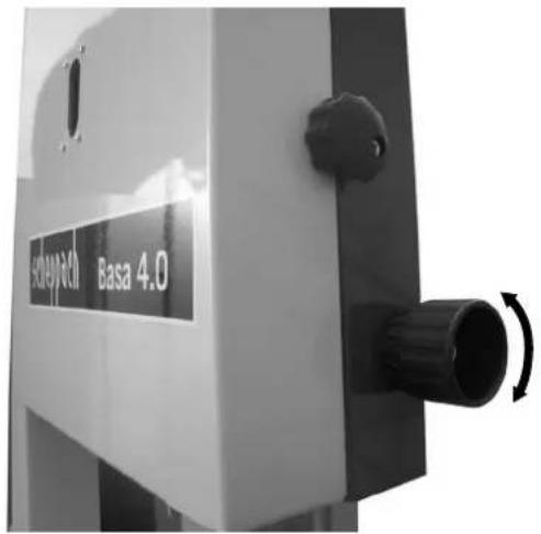
Soleysheet Basa 4.0Fig. 9
natural_image
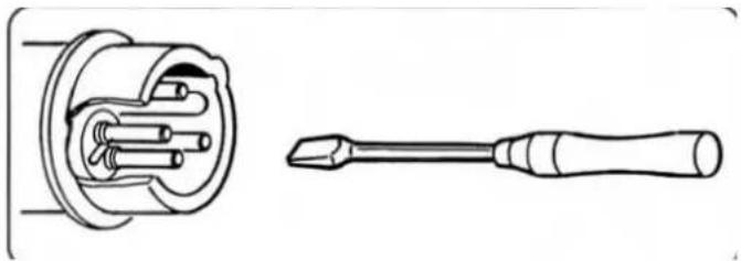
Technical line drawing of a screwdriver and its internal component (no text or symbols)Fig. 7
natural_image
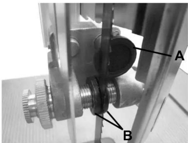
Close-up of a mechanical device with labeled component 'A' (no readable text or symbols beyond label)Fig. 8
text_image
A BLieferumfang
Bandsäge Basa 4.0
Sägeband
Längsanschlag
Schiebestock
Günzburger Straße 69
89335 Ichenhausen
Deutschland
Suction nozzle ∅ 100 mm
Assembly accessories
Operating instructions
Rip fence
Technical Data
| Length/Width/Height mm | 1120x700x1820 |
| Table size mm | 548x400 |
| Work height mm | 1010 |
| Saw band mm | 12x0,65x2955 |
| Band wheel diameter mm | 380 |
| Cutting height at 90° mm | 250 |
| Opening width mm | 375 |
| Table pivoting range Degrees^ | -22,5°/+47° |
| Cutting speed with 2 switch steps m/min | 800 / 1200 |
| Weight kg | 112 kg |
| Motor 230 V / 50 Hz 400 V / 50 Hz | |
| Rated powert input P1 (kW) 1,50 1,50 | |
| Output power P2 (kW) 1,10 1,10 |
Noise Characteristic Values
The noise emission values determined according to EN ISO 3746 for the noise pressure level or according to EN 1807 (correction factor k3 calculated according to Appendix A.2 of EN 1807-1) for the noise pressure level at the work station account for the basis of the working conditions listed in ISO 7960 Appendix J.
The given values are emission values and do not necessarily, therefore, present safe working values at the same time. Although there is a correlation between emission and immission levels, one cannot reliably derive from it whether additional precautions are necessary or not. Factors that can influence the current immission level at the workplace include the duration of activity, the character of the workspace, other sources of noise, etc., e.g. the number of machines and other adjacent processes. The safe workplace values can also vary from country to country. This information should, however, enable the user to undertake a better evaluation of danger and risk.
Sound power level in dB
Idle EVA = 85 dB(A)
Operation EVA = 93 dB(A)
Sound pressure level at work station in dB Idle IpAeq = 71 dB(A)
Operation IpAeq = 86 dB(A)
For the named emission values, the measurement uncertainty tolerance K = 4 dB applies
Statement on Dust Emission
The dust emission values measured according to the “Regulations for the Testing of Dust Emission (Concentration Parameters) of Woodworking Machines” of the Committee of Experts on Wood is under 2 mg/m3. Thus, when the machine is connected to a properly functioning suction with at least 20 m/s air speed, one can assume that the emission will remain safely below the TRK threshold for wood dust that applies in the Federal Republic of Germany.
Depending on the work pieces to be processed or work piece characteristics, pay attention to the load values of the work piece manufacturer.
Machine description
Thanks to its well-engineered construction, the machine can be used in many ways to process wood and plastics in the workshop area.
The upper and lower band wheel is clad by a permanently attached guard and a movable housing cover. When the housing cover is opened, the machine is switched off. Switching on is possible only when the cover is closed. The non-cutting part of the saw band above the table plate is covered by a guard attached to the saw band guide, which in turn is secured against accidental opening by the permanently attached guard on the upper band wheel. The non-cutting part of the saw band under the table plate is clad by a permanently attached guard.
The pivoting range of the table from -22.5^ to +47^ allows for multifaceted cutting options, e.g.:
- Longitudinal cuts
- Cross cuts
- Oblique cuts
- Arched and irregular cuts
• Cuts for dovetails and tenons - Upright cuts for squared timbers
On this point, see also the work notes in the operating instruction.
General Notes
- After unpacking, check all parts for possible transport damage. In the case of complaints, the carrier must be notified at once.
- Later claims are not recognized.
- Check the delivery for completeness.
- Familiarize yourself with the machine by means of the operating instructions prior to installation.
- For accessories as well as expendable and replacement parts, use only original parts. Obtain replacement parts from your scheppach dealer.
- When ordering, give our article numbers as well as the type and model year of the device.
NOTE:
According to the applicable product liability law, the manufacturer of this device is not liable for damages occurring to or through use of this device in the case of:
- improper handling,
- failure to observe the operating instructions.
- repairs by third-party, unauthorized specialists.
- installation and exchange of "replacement parts that are not original scheppach."
- inappropriate use.
- failure of the electrical system due to failure to observe the electrical ordinances and VDE requirements 0100, DIN 57113 / VDE0113.
We recommend:
Before installation and start-up, read the entire text of the operating instructions.
These operating instructions should make it easier to familiarize yourself with your machine and to use its intended installation options.
The operating instructions contain important notes on how to work with the machine safely, correctly and economically and on how to avoid danger, save repair costs, minimize down times and increase the reliability and operating life of the machine.
In addition to the safety requirements of these operating instructions, it is absolutely imperative that you observe the laws of your country that apply for the use of the machine.
Store the operating instructions, in a plastic sleeve
protected against dirt and moisture, near the machine. They must be read by every operator before beginning work and observed carefully. Only those people may work at the machine that have been trained in the use of the machine and instructed regarding the dangers connected with it. The required minimum age must be observed. In addition to the safety notes contained in these operating instructions and the particular laws of your country, the generally recognized technical
rules for operation of woodworking machines are to be observed.
In these operating instructions, we have denoted places that affect your safety with this symbol: △
General Safety Notes
• Pass on the safety notes to all persons who work at the machine.
- Personnel charged with activities on the machine must have read the operating instructions and especially the chapter Safety Notes, before beginning work. Once work has begun, it is too late. This applies to an especial degree for personnel who are active at the machine only occasionally, e.g. for setup, maintenance.
- Observe all safety and danger notes on the machine.
- Keep all safety and danger notes on the machine completely legible.
- Check the mains cables. Do not use defective cables.
- Make sure that the machine is installed in a stable fashion on a strong base.
- Provide sufficient lighting in the working and surrounding area of the machine.
- Caution during work: there is danger of injuring fingers and hands by the rotating cutting tool.
- During work at the machine, all protective equipment and covers must be mounted.
- Keep children away from the machine when it is connected to the mains.
- The operator must be at least 18 years old. Trainees must be at least 16 years old but may operate the machine only under supervision.
- Persons working at the machine may not be
distracted.
- Keep the work surface of the machine free from chips and waste wood.
- Wear close-fitting clothes. Take off jewellery, rings and wristwatches.
- Wear safety glasses during work.
• To protect long hair, wear a cap or hair net. - Wear suitable gloves to change the saw band.
- Do not wear work gloves when working at the saw.
- Observe the correct rotational speed setting on the machine.
- The protective devices on the machine may not be removed or rendered unusable.
- Carry out retrofitting, adjustment, measurement and cleaning tasks only when the motor is switched off. Pull out the plug and wait for the rotating tool to come to a stop.
• Installations, repairs and maintenance work to the electrical installation may be carried out only by professionals. - All protective and safety guards must be re-mounted immediately after completed repair and maintenance work.
- To correct problems, switch off the machine. Pull out the plug!
- To suction off wood chips or sawdust, install a suction system. The flow velocity at the suction nozzle must be 20m/s.
-
Before start-up, check the saw band guide as well as the saw band tension.
-
Use only sharpened saw bands.
- Do not use cracked saw bands, or those that have changed their shape.
- If the saw slit is worn, exchange the table insert.
- When sawing round pieces of wood, secure the work piece against turning.
- To saw hard or unwieldy pieces, use suitable tools for support. Special accessory: Roller carrier and all-sides roller carrier.
- Place the upper saw band guide as close as possible to the work piece.
- If the table plate is set in an oblique position, set the longitudinal fence on the lower table plate half.
• After switching off the motor, do not brake the saw band with side pressure. - Remove sawed-off, jammed work pieces only when the motor is switched off and the saw band has stopped
- Disconnect the machine from all external power sources for even negligible relocations! Before starting up again, properly reconnect the machine to the mains.
- When you leave the workplace, switch off the motor. –Pull out the plug!
- If the band saw blade or belt rips, switch off the band saw and wait for it to come to a stop.
- Never remove chips when the saw is running.
- Do not use the machine to cut round or irregularly shaped work pieces (e.g. firewood).
Intended Use ⚠️
- The machine adheres to the applicable EU Machines Directive.
- The machine is not suitable for the industrial sector (permanent installation).
- Before beginning work, all protective and safety equipment must be mounted on the machine.
- The machine is designed for use by one person. The operator is responsible for third parties in the work area.
- Observe all safety and danger notices on the machine.
- Keep all safety and danger notices on the machine completely in a legible condition.
- The band saw is designed to be used with the provided tools and accessories exclusively for sawing wood, wood-like materials and non-ferrous metals.
- The maximum dimensions of the work piece to be processed may not exceed the table size in the standard configuration. Aperture width 375 mm, aperture height 250 mm
- For larger work piece dimensions, which require a tipping of the table plate, the table extension or the roller carrier (special accessory) is to be used.
- The band saw can be used with the special saw blade (special accessory) as well as its speed adjusted to saw metal as well. Material alloys with more than 80% magnesium may not be processed due to fire danger.
-
When used in enclosed spaces, the machine must be connected to a suction system. Install a suction system to suction off wood chips or sawdust. The flow velocity at the suction nozzle must be 20m/s. Vacuum 1750 Pa (Please provide corresponding suction devices). Diameter of the suction nozzle 100 mm
-
The automatic switch-on is available as a special accessory.
- When the work machine is switched on, the suction turns on automatically after a 2- to 3-second switch-on delay. An overloading of the mains is thus prevented.
• After the work machine is switched off, the suction runs for another 3-4 seconds and then switches off automatically. - The remaining dust is thereby suctioned off, as required in the Ordinance on Hazardous Substances. This saves energy and reduces noise. The suction system runs only while the work machine is operated.
- For work in the industrial sector, a vacuum that meets the industrial regulations must be installed for the suction.
- Suction system must be switched on before operation.
- Do not switch off or remove the suction systems or dust extractor while the machine is running.
- Use the machine only in a technically flawless state as well as properly, aware of safety and danger and with due consideration for the operating instructions! In particular, completely repair problems that can influence safety (or have them repaired)!
- Pay attention to the safety, operating and maintenance requirements of the manufacturer as well as the dimensions given in the Technical Data.
- Observe all applicable accident prevention ordinances and the other generally recognized safety-technical rules.
• The machine may be used, maintained or
Type ALV2 Art.No.79104010 230V/50Hz, Type ALV10 Art.No.79104020 400V/230V/50Hz
repaired only by experienced persons who are assigned to do so and who are instructed regarding the dangers. Independent changes to the machine exclude a liability of the manufacturer for resulting damages.
- Only operate the machine with original accessories and original tools from the manufacturer.
- Any use that goes beyond these terms is considered improper. The manufacturer is not liable for damages resulting from such use; the user alone bears the risk thereof.
Warning Symbols / Warning Notes

Read the handbook before start-up

Use hearing protection and safety glasses
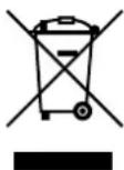
Only for EU countries Do not throw electronic tools in the household garbage! According to the European Directive 2002/96/EG on restriction of hazardous substances and implementation in national law, worn-out electronic tools must be collected separately and transported to an environmentally sound recycling
Residual Risks ⚠️
- The machine is built according to the state of the art and the recognized safety-technical rules. Nevertheless, individual residual risks can arise during operation.
- Danger of injury to fingers and hands from the rotating saw blade due to improper guiding of the work piece.
- Injuries from the work piece being flung away due to improper holding or guiding, such as work without a fence.
- Danger to health from sawdust or wood chips. It is imperative that the operator wear personal protective equipment like eye
protection and dust masks. Install suction system!
- Injuries from defective saw band. Check the saw band regularly for integrity.
- Injury danger to fingers and hands during saw band exchange. Wear suitable work gloves.
- Injury danger while switching on the machine from the saw band turning on.
- Danger from current when using improper electrical connection leads.
-
Hearing damage. Wear suitable hearing protection.
-
Never clean the band saw blades while the machine is running.
- Danger to health from the running saw blade with long hair and loose clothing. Wear personal protective equipment such as a hair net and close-fitting work clothes.
• Moreover, in spite of all preventative measures being taken, unforeseeable residual risks can still arise. - Residual risks can be minimized if the "Safety Notes" and "Intended Use" as well as the operating instructions as a whole are observed.
Transport
The machine may be transported only with suitable lifting devices (crane or lift truck). The upper band wheel box is to be used as the sling point for the cable.
Never lift the saw table!
Using the transport device (Accessory Art. No.: 7901504701)(Fig. 1):
To use the transport device, insert the transport handle (A) in the transport handle opening. (After inserting the transport handle (A), turn it a bit so that it cannot slide out)
Now lift the machine on the transport handle (A) far enough that the machine stands on the two rear wheels (B) and can be moved.
Pay attention to the machine's high centre of gravity (top-heavy)
Set-up / Storage
Prepare the work station at which the machine should stand. Create enough space to enable safe, uninterrupted work. The machine is designed for work in enclosed spaces and must be set up in a stable manner on a level, firm base. At least two people are required to lift down the pallet. Based
on the work setting, tip the machine to the left and pull out the pallet to the right.
To prevent the machine from slipping, it is possible to screw it to the floor. Through-holes are attached to the floor plate for this purpose.
Storage requirements:
Make sure that the machine is stored in a dry place.
Minimum temperature: +5^
Maximum temperature: +40°
Start-up
Your machine is delivered completely assembled; nevertheless, it may be that you still need to make small adjustments.
Check the saw band tension before every start-up
Operating requirements:
Make sure that the machine is operated in a dry place.
Minimum temperature: +5°
Maximum temperature: +40°
Saw band
The selection of the right saw band is crucial for the cutting performance.
Pay attention to the table for selection of the saw bands in the operating instructions.
With small saw bands, you can cut smaller radii than with wide saw bands.
Use only well-sharpened, flawless saw bands. Defective saw bands increase the risk of accidents and reduce work performance
Changing the saw band
Caution: Pull out the plug!
- Open the saw band guard. To do this, open the closing knob (Fig.2 "A"). Now open the star grip screw (Fig.2 "B") far enough that the door can be opened. This star grip screw simultaneously operates the end switch that prevents the saw from turning on while the door is open.
- To prevent the door from falling shut, unfold the bar (Fig.3 "A").
- Also open the adjustable saw blade guard (Fig.2 "C").
- To relax the band wheel, use the quick release skewer (Fig.4 "A") (move the lever clockwise).
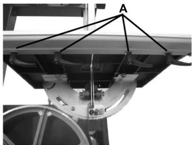
- Unfold the guide pipe for the longitudinal fence so that you can pull out the saw band. Open the 4 wing screws (Fig.5 "A") in order to be able to unfold the guide pipe.
- Insert the new saw band.
- Turn the band wheel manually in the cutting direction and adjust the final tension with the hand grip at the same time. The tension depends on the saw band width. Wide saw
bands are to be tensioned more strongly than small ones. For fine adjustment of the saw band tension, use the adjustment screw (Fig.4 "B").
- Caution: Too high tension leads to early breakage! Always relax the saw band after ending the band saw work! To do this, use the hand grip (Fig.4 "A").
Side correction
- The saw band should run about in the middle of the band wheels.
- Turn the upper band wheel by hand in the cutting direction and carry out the side correction with the hand grip (Fig.4 "C").
• After successful adjustment, tighten the wing nut on the hand grip.
You can adjust the upper saw band guide up to 250 mm work piece height (Fig. 6). Keeping the distance to the work piece as small as possible to ensure optimal band guidance and safe work!
Rotational speed adjustment
Caution: Pull out the plug!
- Open the saw band guard and secure it with the bar.
- Loosen the tommy screw (Fig.7 "A") on the side of the motor; relax the belt. Change belt as needed.
- Now set the desired rotational speed: Step 1 = 1200 m/min Step 2 = 800 m/min
- Bring the belt to tension and tighten the
tommy screw again. Finally, close the saw band guard.
Counterthrust bearing
The counterthrust bearing (Fig.8 "A") absorbs the feed pressure of the work piece.
Adjust the upper and the lower counterthrust bearing such that it lightly runs along the back of the saw band.
Guide rollers
Adjust the upper and lower guide rollers (Fig. 8 "B") to the respective saw band width. The leading edge of the guide rollers may reach up to the highest tooth depth of the saw band. When the guide rollers lightly touch the saw band, lock the position of the rollers with the knurled screw.
The saw band must not jam!
Work Hints
The following recommendations are examples for the safe use of band saws.
The following safe work methods are considered contributions to safety, but they are not suitable for every use, complete or universally applicable. They cannot cover all potential dangerous conditions and must be interpreted carefully.
- Before every use, check all protective and safety equipment for functionality.
- It is only possible to saw with the band saw when the saw band cover is closed. Thus, the saw band cover can be opened only when the machine is stopped.
- Only use saw bands with a minimum width of 6 mm and a maximum width of 20 mm. The thickness must be 0.65 mm.
- Test the functionality of the emergency stop before every start-up.
- Test the functionality of the end switch when the doors are open before every start-up.
- When working in enclosed spaces, connect the machine to a suction system. For work in the industrial sector, a vacuum that meets the industrial regulations must be installed.
- When the machine is not being used, e.g. at the end of work, relax the saw band. Attach a note to the machine for the next user to
tension the saw band.
- Store unused saw bands folded and securely in a dry place. Before use, check for defects (teeth, cracks). Do not use defective saw bands!
- Wear suitable gloves when handling saw bands.
- Before beginning work, all protective and safety equipment must be mounted on the machine.
- Never clean the saw band or the saw band guide with a handheld brush or scraper while the saw band is running. Saw bands coated with resin endanger the work safety and must be cleaned regularly.
- For your personal protection while working, wear safety glasses and hearing protection. If you have long hair, wear a hair net. Roll loose sleeves up to above the elbows.
- While working, always position the saw band guard as close as possible to the work piece.
- Provide sufficient lighting in the working and surrounding area of the machine.
- For straight cuts, always use the longitudinal fence to prevent the work piece from tipping or slipping away.
- For flat cuts with thin work pieces, use the
low end of a fence so that the adjustable separating guard can be used.
- To process small work pieces with manual feed, use the push stick (especially if you will be pushing past close to the saw band).
- For oblique cuts, bring the saw table into the corresponding position and guide the work piece along the longitudinal fence.
- To cut dovetail joints and tenons or keying, pivot the saw table respectively in the plus and minus position. Pay attention to safe work piece guidance.
- For arched and irregular cutting of the work piece, push the piece forward steadily with both hands, keeping the fingers closed. Grip the work piece with the hands in the safe area.
- For repeated execution of arched, irregular cuts, use an auxiliary template.
- To cut small keys, use a guiding device.
- For safe work with cross cuts, use the special accessory rip fence.
- For safe work when cutting round plates use a circle-cutting device.
- Make sure that push stick and push wood are regularly replaced.
Electrical Connection
The installed electric motor is connected and ready for use.
The connection conforms to the applicable VDE and DIN regulations.
The customer-side mains connection and the extension cord used must meet these regulations.
Installations, repairs and maintenance tasks to the electrical installation may be carried out only by a professional.
Important Notes
The electric motor is designed for Operation Type S 1.
If the motor is overloaded, it switches off automatically. After a cool-down period (which varies in length), the motor can be switched on again.
Damaged electrical cords
Insulation damage often occurs to electric power cables. Causes are:
-
Pressure points, if cords are run through window or door gaps.
-
Bent points, due to improper securing or running of the cords.
- Cut points due to running over the cords.
- Insulation damage due to ripping out the plug from the wall socket.
- Cracks due to aging of the insulation.
Do not use such damaged power cords and they
pose life-threatening danger due to the insulation damage.
Regularly check power supply cords for damage. Make sure that during such checks, the cord is not connected to the mains voltage.
Power supply cords must adhere to the relevant VDE and DIN requirements. Use only cords labelled HO 7 RNF. An imprint of the classification on the cords is required.
Alternating current motor
- Mains voltage must be 230 V/50 Hz.
- Extension cords must have a cross-section of 1.5 mm^2 up to a length of 25 m, over 25 m at least 2.5 mm^2 .
- The mains connection is slow-blowing fused
with 16 A.
Three-phase alternating current motor
- Mains voltage must be 400 V/50 Hz.
- Mains connection and extension cords must be 5-poled = 3 P + N + earth.
- Extension cords must have a minimum cross-section of 1.5 mm ^4 .
- The mains connection is fused with maximum 16 A.
- During connection to the mains or change in location, the rotational direction must be checked; if necessary, change the polarity. (Fig.9)
For correspondence, please supply the following data:
- Motor manufacturer
- Current type of the motor
- Data of the machine rating plate
- Data of the switch rating plate
When returning the motor, always send the complete drive unit with the switch.
Maintenance and Repair
Carry out retrofitting, adjustment, measurement and cleaning tasks only when the motor is switched off. Pull the plug and wait for the rotating tool to come to a stop. As an experienced craftsman, you may carry out small repairs to the machine yourself.
Repairs and maintenance tasks on the electrical system may be carried out only by a
qualified electrician.
All protective and safety equipment must be re-mounted on the machine immediately after completion of repair and maintenance work.
We recommend:
- The pivot segments of the table, the saw band tension device and the guide of the cut height position should always be easy to
move. Treat these parts with a lubricant as needed to maintain these functions.
- Clean the saw band regularly. Wood leaves behind resin residues that gum up the saw band and affect both the work safety and the work process.
• Always keep the table surface free of resin. - Do not use cleaners or solvents that are easily flammable or that give off hazardous fumes to clean the saw band and table.
Use the special accessory Resin Remover Concentrate.
- When exchanging the table insert, make sure that the insert is at the same height as the saw table.
- Regularly check the saw band for defects. Replace defective saw bands immediately.
- Regularly check the saw table insert. Re-
place worn saw table inserts.
- Rubber bandage of the band wheels The rubber bandage on the band wheels becomes cracked and worn over time due to the metal saw band. An exact saw band run is therefore no longer possible. The work safety and the work process are affected.
Exchange band wheels!
Obtain replacement band wheels, as well as all other replacement parts through your scheppach dealer.
- Regularly check the adjustment of the saw band guide and reset it as needed. To adjust, remove the saw band guide.
Troubleshooting
| Problem Possible | Causes Remedy | |
| Motro does not turn on a) No power | a) Check mains fuse | |
| b) Switch, capacitor defective b) Have a qualified | electrician check it | |
| c) Electrical extension cord defective c) Remove | mains fuse, check, exchange if needed | |
| d) Wrong flex 3~400V Motor d) Flex 5-poled, at 1 | 5 mm^2 cross-section | |
| e) Housing cober open (end switch) e) Close housing cover exactly | ||
| Motor turns the wrong direction | Incorrect connection | Change rotational direction at CEE plug |
| Saw band wanders or jumps down | a) Upper band wheel | a) Carry out side correction |
| b) Saw band guide | b) Reinstall | |
| c) Wrong saw band | c) Select from scheppach catalogue | |
| d) Longitudinal fence not parallel to saw band | b) Adjust longitudinal fence | |
| Scorch mark on wood during work | a) Saw band dull | a Replace saw band |
| b) Wrong saw band | b) Select from scheppach catalogue | |
| c) Wrong cutting speed | c) Adjust cutting speed | |
| d) Longitudinal fence not parallel to saw band | d) Adjust longitudinal fence | |
| Saw band jams during work | a) Saw band dull | a) Replace saw band |
| b) Saw band resined | b) Clean saw band | |
| c) Guide badly adjusted | c) Readjust | |

If you have problems and cannot resolve them yourself, contact the customer service of the scheppach company.
EU-Conformity Declaration
Günzburger Straße 69
89335 Ichenhausen
Deutschland
Representative: Werner Hartmann
We, the scheppach Fabrikation von Holzbearbeitungsmaschinen GmbH, declare that the machine described below
Table band saw Basa 4.0, from Series number 1001, Article No. 1901504901, Article No. 1901504902
conforms to all relevant requirements of the EU-Machines Directives 2006/42/EG
Other EU directives: EU EMC Directive 2004/108/EWG
Switched on for the: EC Type Approval Testing
Certifications: EC Type Approval Certification (Ho 123)
The following person is commissioned for the collection of the technical documents:
Reinhold Bauer
by proxy Reinhold Bauer (Construction manager)
Documentation representative
R.Bauer
Günzburger Straße 69
89335 Ichenhausen
Deutschland
Mandataire: Werner Hartmann
Wear suitable work gloves when handling saw bands!
- Saw band should be handled carefully to protect them from damage.
- Collect untensioned sawbands which are not in use and secure them with a band.
- Store sawbands in a dry place away from children in the original packages.
- Check for faults like faulty teeth
FR
text_image
Exploded view diagram of a refrigerator with detailed component labels and part numbers in Chinese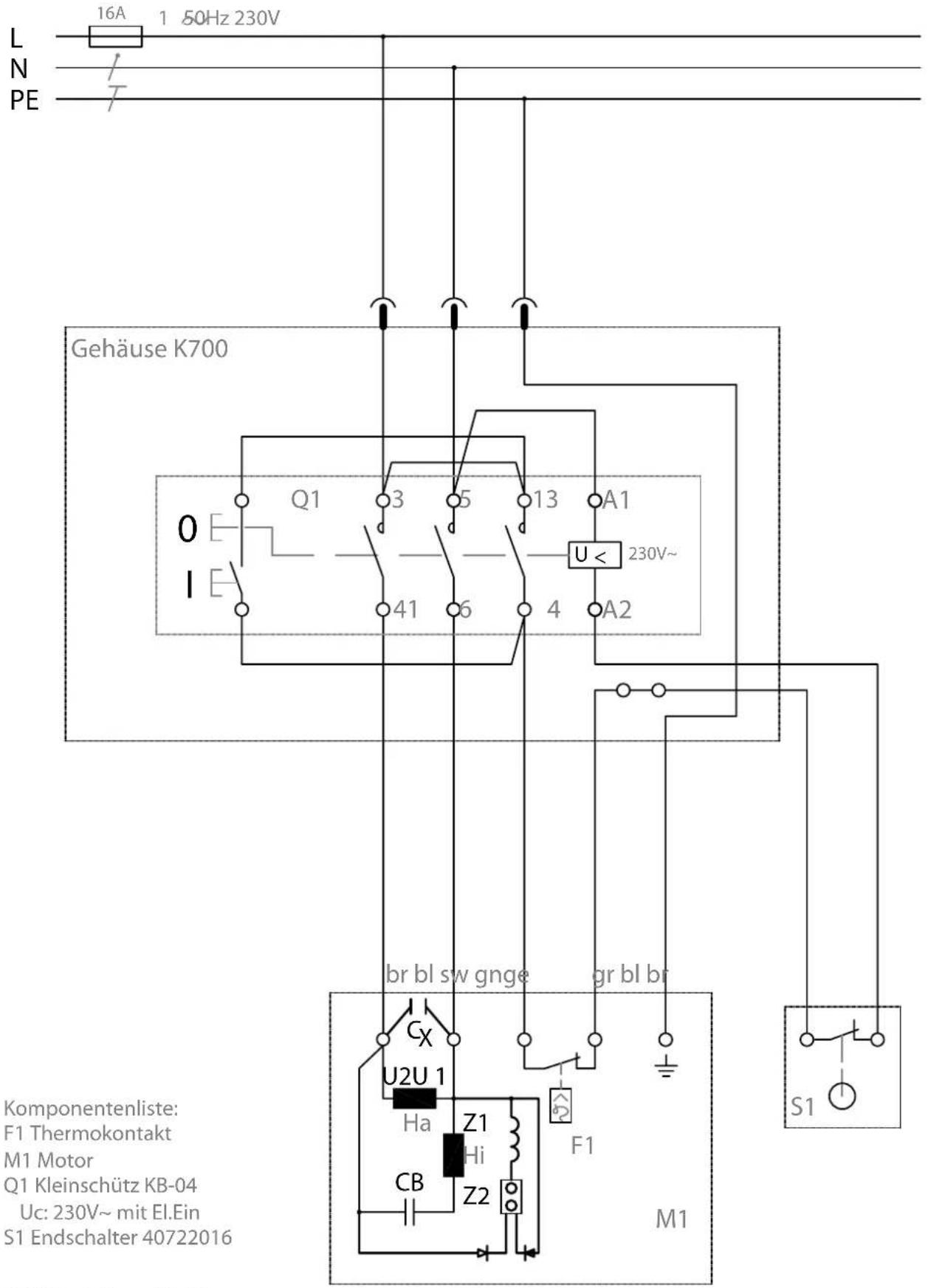
text_image
L N PE 16A 1 50Hz 230V Gehäuse K700 Q1 3 5 13 A1 41 6 4 A2 U < 230V~ br bl sw gnge gr bl br Cx U2U 1 Ha Z1 Hi CB Z2 F1 M1 Komponentenliste: F1 Thermokontakt M1 Motor Q1 Kleinschütz KB-04 Uc: 230V~ mit El.Ein S1 Endschalter 40722016Apparent defects must be notified within 8 days from the receipt of the goods. Otherwise, the buyer's rights of claim due to such defects are invalidated. We guarantee for our machines in case of proper treatment for the time of the statutory warranty period from delivery in such a way that we replace any machine part free of charge which provably becomes unusable due to faulty material or defects of fabrica-
tion within such period of time. With respect to parts not manufactured by us we only warrant insofar as we are entitled to warranty claims against the upstream suppliers. The costs for the installation of the new parts shall be borne by the buyer. The cancellation of sale or the reduction of purchase price as well as any other claims for damages shall be excluded.