Duo 7.0 - Saw SCHEPPACH - Free user manual and instructions
Find the device manual for free Duo 7.0 SCHEPPACH in PDF.


User questions about Duo 7.0 SCHEPPACH
0 question about this device. Answer the ones you know or ask your own.
Ask a new question about this device
Download the instructions for your Saw in PDF format for free! Find your manual Duo 7.0 - SCHEPPACH and take your electronic device back in hand. On this page are published all the documents necessary for the use of your device. Duo 7.0 by SCHEPPACH.
USER MANUAL Duo 7.0 SCHEPPACH
text_image
Scheppach Duo 7.0 Duo 7.0Duo 7.0
| D | KombinationsmaschineOriginal-Anleitung |
| GB | Combined Wood Working machineTranslation from the original instruction manual |
| FR | CombinéTraduction du manuel d'origine |
| D | Kombimaschine | 7-12 |
| GB | Combined Wood Working Machine | 13-18 |
| FR | Combiné | 19-24 |
text_image
A 4 2 3 1 9 7 6 8 5 10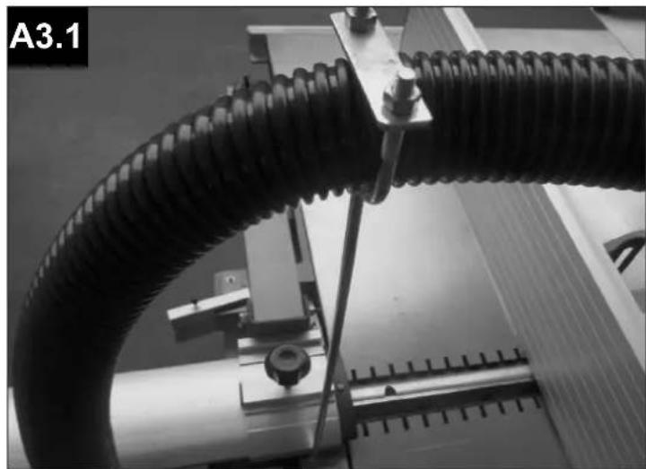
natural_image
Close-up of a black corrugated cable being handled by a mechanical assembly (no visible text or symbols)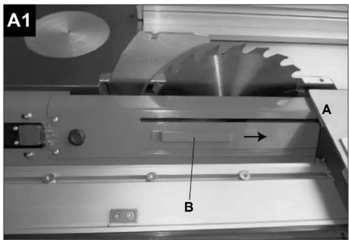
text_image
A1 A B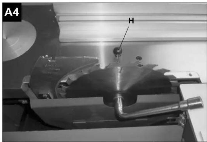
text_image
A4 H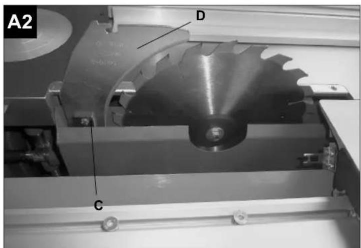
text_image
A2 D C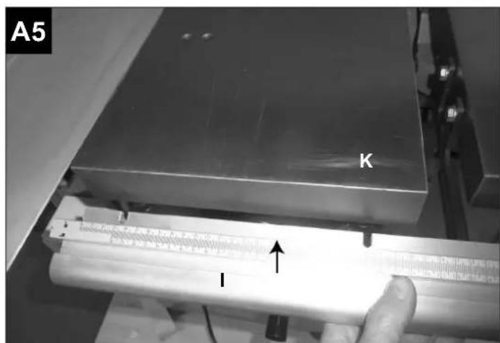
text_image
A5 K I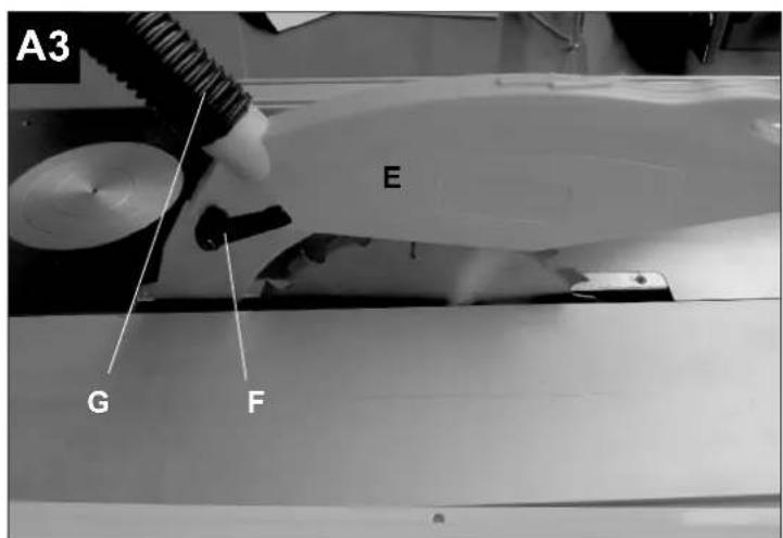
text_image
A3 E G F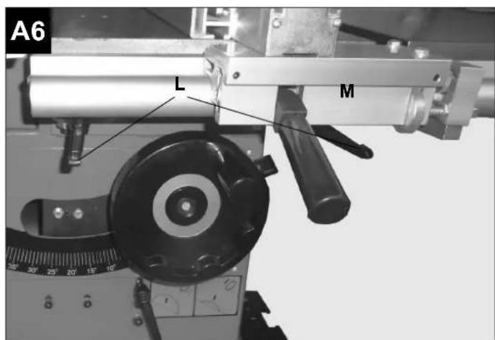
text_image
A6 L M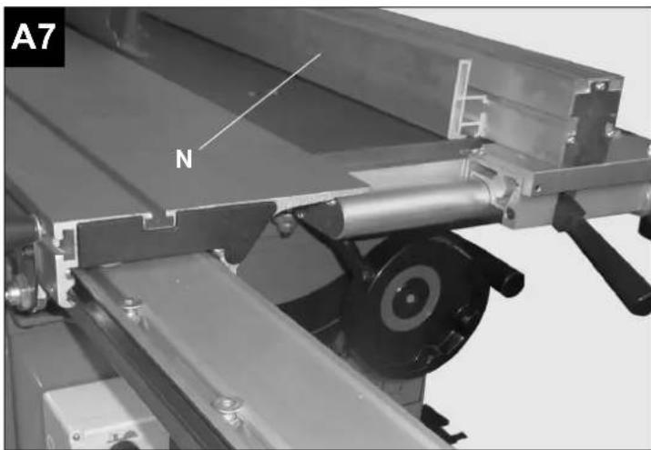
natural_image
Mechanical assembly diagram showing a rotating component with labeled part 'N' and section marker 'A7' (no readable text or symbols beyond labels)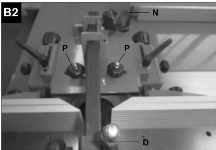
text_image
B2 N P P D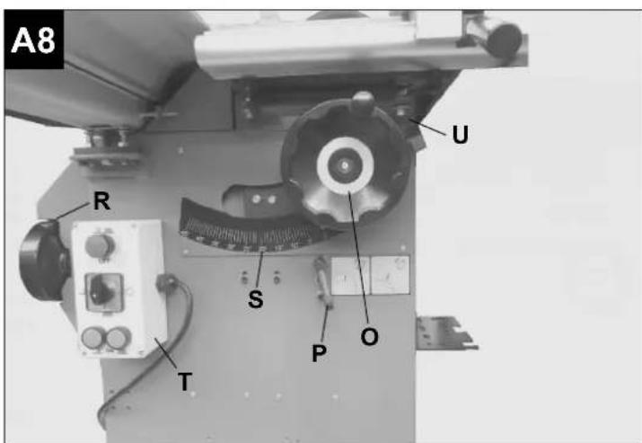
text_image
A8 R U S T P O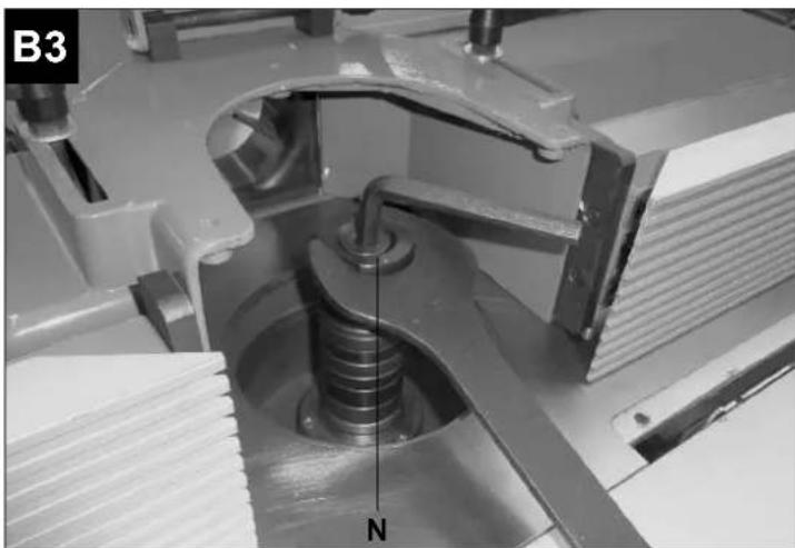
natural_image
Mechanical assembly diagram showing a spring mechanism with labeled component 'N' (no readable text or symbols beyond label)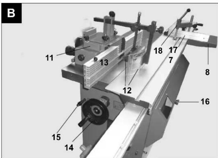
text_image
B 11 13 12 18 17 7 8 16 15 14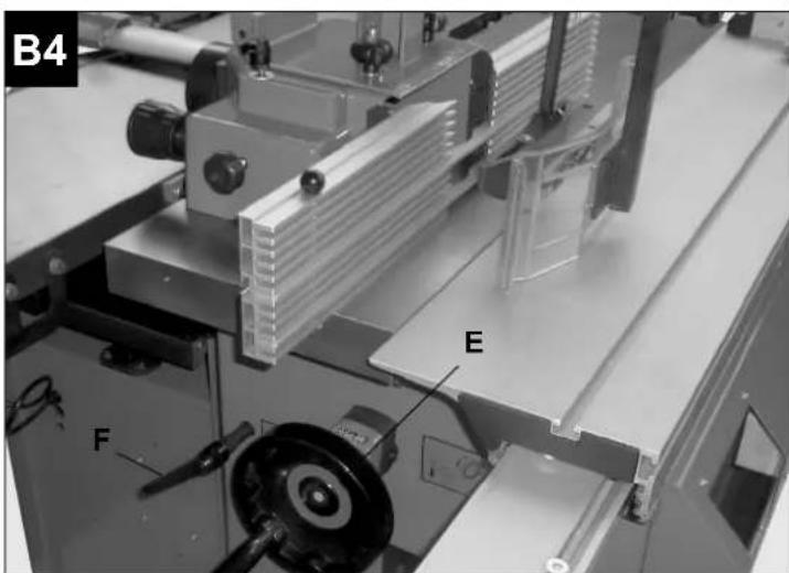
text_image
B4 E F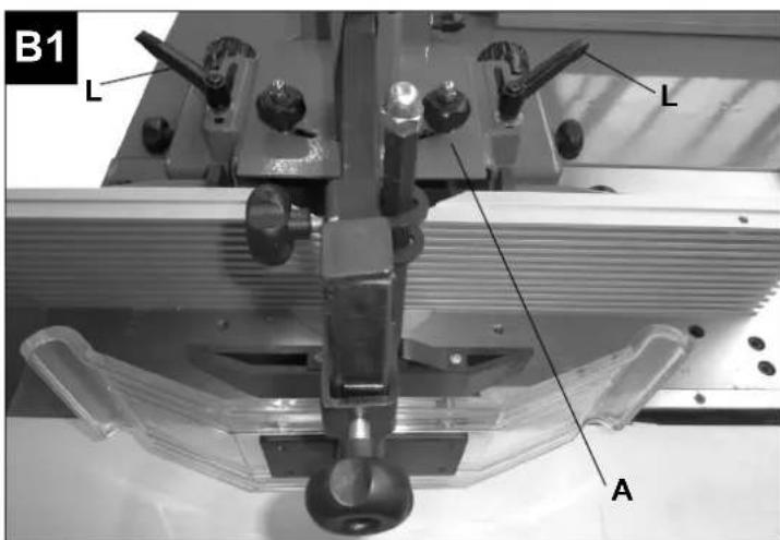
text_image
B1 L L A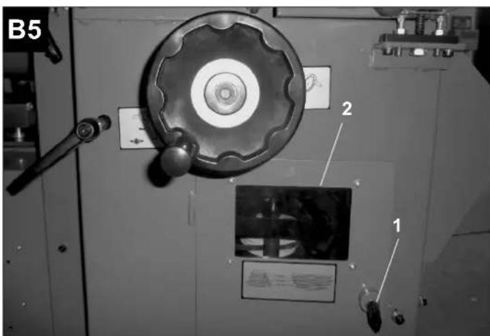
text_image
B5 2 1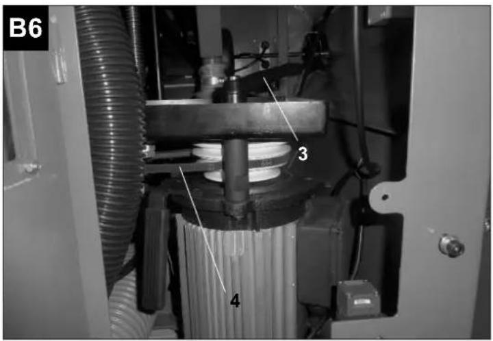
text_image
B6 3 4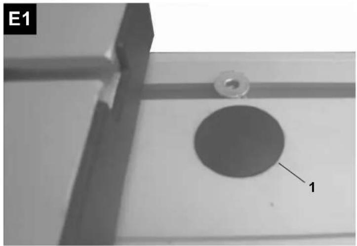
natural_image
Close-up of a mechanical component with a circular hole and labeled part '1' (no text or symbols beyond label)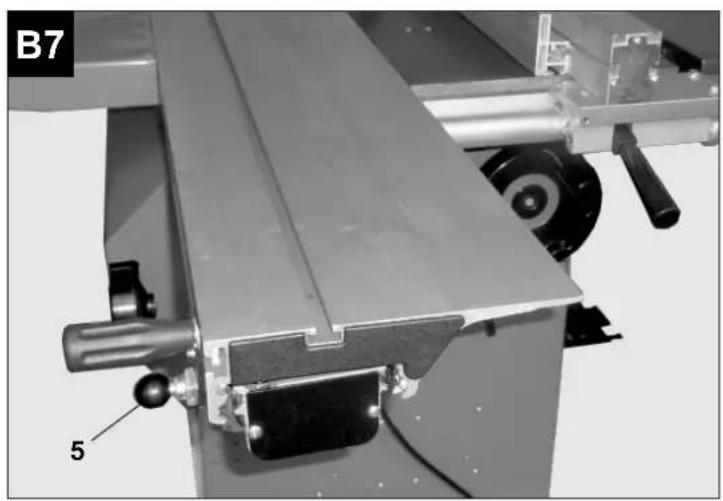
natural_image
Mechanical assembly with labeled component '5' and part identifier 'B7' (no readable text or symbols beyond labels)
text_image
E2 2 3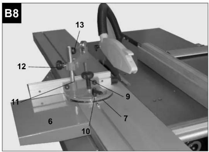
text_image
B8 13 12 11 6 9 7 10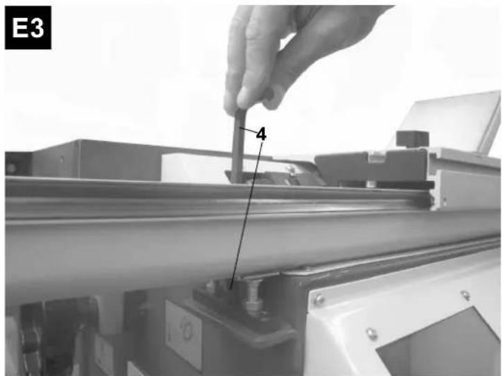
text_image
E3 4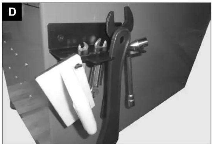
natural_image
Black-and-white photo of a wall-mounted wrench and clamp tool holder (no text or symbols visible)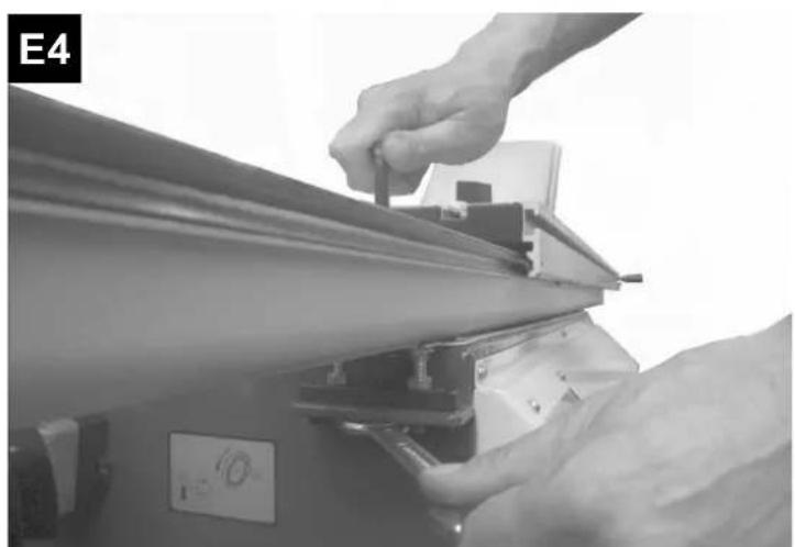
natural_image
Close-up of hands operating a mechanical device with a tool, no visible text or symbols
text_image
L 16A N 16A PE L1N1 SB1 3 KM2 M12 KM3 L13 M13 SB4 SQ5 5 SQ4 7 L12 SB6 DB3 11 SB5 19 M2 KM3 KM2 BENCHMARKING 13 KM3 21 15 SA400 V
text_image
L1 L2 L3 N PE 6A16 6A L11 L21 L31 KM2 L12 L22 L32 KM3 L13 L23L33 M3 BENCHMARKING SB1 3 SQ5 5 SQ4 7 SB4 9 DB3 11 SB6 KM3 13 KM3 DB2 17 SB5 KM2 19 KM2 21 SA 15Lieferumfang
Inbusschlüssel 4/5/6 mm
Gabelschlüssel 10/13/17 mm
Restrisiken ⚠️
Kreissäge (A)
| Standard delivery | Milling machine | Operating instructions |
| Saw | Milling stop with vernier adjustment | Installation tool |
| HM saw blade D 300 | Insertion stop | |
| Longitudinal stop | Distance ring | |
| Trimming stop | ||
| Slide rod |
Technical data
| Product dimensions | |
| Total length mm | 2000 |
| Total width mm | 1320 |
| Total height mm | 1130 |
| Weight kg | ca. 240 |
| Saw | |
| Table length mm | 900 |
| Table width mm | 400 |
| Max. cutting height mm | 82 |
| Max. cutting height at 45° mm | 68 |
| Cutting width with longitudinal stop mm | 600 |
| Saw blade wivel range Degree | 0 - 45 |
| Saw blade height adjustment mm | 0 - 82 |
| Saw blade rotary speed 1/min | 4000 |
| Milling machine (Spindle Moulder) | |
| Table length mm | 1145 |
| Table width mm | 300 |
| Milling spindle ∅ mm | 30 |
| Tool ∅ max. mm | 140/200 |
| Table opening ∅ mm | 150 |
| Tool clamping height mm | 100 |
| Height adjustment of spindle mm | 130 |
| Spindle rotation speed 1/min | 3500/5500/7000 |
| Model Duo 7.0 (Art. No.: 1902404901) | Duo 7.0 (Art.No.: 1902404902) | |
| Motor Saw 230V±10% (50Hz±1%Hz) 400V±10% (50Hz±1%Hz) | ||
| Input power P1 3,0 kW S6 40% 3,0 kW | S6 40% | |
| Output power P2 2,3 kW S6 40% | 2,36 kW S6 40% | |
| Motor speed | 2800 1/min | 2820 1/min |
| Nominal current | 13,0 A | 5,4 A |
| Motor milling machine | 230V±10% (50Hz±1%Hz) 400V±10% (50Hz±1%Hz) | |
| Input power P1 | 3,0 kW | 3,0 kW |
| Output power P2 | 2,3 kW | 2,35 kW |
| Motor speed | 2820 1/min | 2820 1/min |
| Mode | S1 | S1 |
| Nominal current | 13,4 A | 5,6 A |
S6 %40, continuous operation periodic duty: time of one load cycle is 10 minutes, operation time at constant load is 4 minutes, operation time at no-load is 6 minutes.
Machine Environmental data
Operation: Altitude <=1000m, Temperature: 5\~40Celsius Degree, Humidity: 40Celsius Degree <=50%, 20Celsius Degree <=90% Transportation & storage temperature (Celsius Degree): -25\~+50
Noise emission
Saw
Noise output level in dB
LWA idle run = 95.4 dB(A)
LWA processing = 99.6 dB(A)
Sound pressure level at workplace in dB
LqAeq idle run = 78.6 dB(A)
LqAeq processing = 83.2 dB(A)
Milling machine
Noise output level in dB
LWA idle run = 93.3 dB(A)
LWA processing = 96.9 dB(A)
Sound pressure level at workplace in dB
LqAeq idle run = 78.5 dB(A)
LqAeq processing = 81.2 dB(A)
Noise characteristic values / measurement conditions
The specified values are emission values and need not simultaneously represent safe labour values. Though there is a correlation between emission and immission levels, one cannot derive from this correlation reliably, whether additional precautionary measures are necessary. Factors that can influence the existing immission level at the current workplace, contain the duration of the effects, the peculiarity of the work room, other noise sources etc., e.g., the number of machines and operations in the vicinity.
The permissible labour values may also vary from country to country. This information should however enable the user to make a better assessment of the involved dangers and risks. For the mentioned emission values, a measurement safety allowance of K = 4 dB is applicable.
Data on dust emission
The dust emission values measured in accordance with the "principles of testing dust machines (concentration parameters) before
wood processing machines" of the Wood Specialized Committee lie below 2 mg/m3. Hence, while connecting the machine to a proper and effective vacuum cleaner with min. 20 m/s air speed, one can presume a permanently safe observation of the TRK threshold for wood dust applicable in the Federal Republic of Germany. Use hearing- or ear protection. Use protective masks and goggles. Use eye protection. In this operating instructions manual, we have used the following sign at places that affect you safety: △
General instructions
- Check all components for possible transport damages after unpacking. In case of complaints, the person responsible for the delivery must be contacted. Complaints made later shall not be entertained.
- Check to ensure that the delivery is complete.
- Familiarize yourself with the device with the help of the operating instructions manual before using it.
- Use only original accessories as well as consumables and spare parts. Spare parts are available at your Scheppach specialised dealer.
- Please quote our Article numbers as well as type and year of manufacture of the device in your orders.
NOTE:
- According to the applicable Product Liability Law, the manufacturer of this device shall not be liable for damages to this device or damages caused by this device in case of:
- Improper handling,
• Non-observation of the operating instructions manual,
• Repairs by third parties, unauthorized fitters,
• Installation and use of non-original spare parts, - Improper use of the machine,
- Failure of the electrical system due to the non-observation of the electrical specifications and VDE provisions 0100, DIN 57113 / VDE0113.
We recommend the following:
Read the entire text of the operating instructions manual before installation and start-up. This operating instructions manual is expected to help you familiarize yourself with the machine and to use it as per the manufacturer's instructions. The operating instructions manual contains important instructions about how you can work with the machine safely, economically and properly, and about how you can avoid risks,
repair costs, reduce downtime and increase the reliability and life span of the machine. In addition to the safety provisions of this operating instructions manual, you must also observe the specifications of your country applicable to the operation of the machine without fail.
Keep the operating instructions manual in a plastic cover near the machine to protect it against pollution and humidity. It must be read carefully and observed by all operators before starting work on the machine. Only persons who are trained to operate the machine and have been instructed about the associated risks may work on the machine. The required minimum age must be observed. In addition to the safety instructions listed in this operating instructions manual and the special regulations of your country, the universally recognized technical rules must also be observed.
General safety instructions
- Forward the safety instructions to all persons who work on the machine.
- Use the machine only if it is in a flawless condition technically, and only after learning about its proper and safe use, as well as about the risks involved, complying with the operating instructions! Get faults that compromise safety in particular rectified immediately
- Only tools that correspond to the European Standard EN 847-1 may be used.
- All safety- and risk instructions on the machine
- Keep all safety and risk instructions on the machine in complete and readable condition.
- The circular table saw may not be used to cut firewood.
- Caution during work: Risk of physical injury to fingers and hands from the rotary cutting machine.
- Please ensure that the machine is stable and that it is installed on firm ground.
- Check the mains power cables. Do not use any faulty cables.
- Keep children away from the machine connected to the power supply.
- The age of the operator should be minimum 18 years. Trainees must be minimum 16 years old, but they can work on the machine only under supervision.
- The attention of the persons working on the machine should not be diverted
- If a second person is working at the circular table saw to remove the cut workpieces, the machine must be equipped with a table extension. The second person should be positioned only at the pick-up end of the table extension.
- Keep the operator console of the machine free of wood shavings and chips.
- Wear tight-fitting clothes. Remove ornaments, rings and wrist-watches.
- Observe the direction of rotation of the motor – see the electrical connection.
- The safety devices on the machine are not to be dismantled or disabled.
- Conversion-, adjustment-, measurement- and cleaning jobs are to be performed only after the motor is switched off. Disconnect the power plug and wait for the rotating tool to stop.
- For troubleshooting, switch the machine off and disconnect the power plug from the mains socket.
- The machine must be connected to a vacuum cleaner during all operations. Please observe the "Proper use according to manufacturer instructions" for this.
- When working on the machine, all safety devices and covers must be installed.
• Install only well-sharpened, crack-free and not-deformed saw blades.
• Circular saw blades made of high-performance fast steel should not be installed. - The safety devices on the machine are not to be dismantled or disabled.
- The splitting wedge is an important safety device which guides the workpiece and prevents the closure of the saw kerf behind the saw blade, and the rebounding of the workpiece. Pay attention to the splitting wedge thickness, see the numbers punched on the splitting wedge. The splitting wedge may not be thinner than the saw blade body and not thicker than its saw kerf width.
- Lower the covering hood on the workpiece during each operation
- The covering hood must be horizontal during each operation
- During longitudinal cutting of small workpieces – smaller than 120 mm - use the slide rod without fail. The slide rod must be used to prevent working with the hands in the vicinity of the saw blade.
- Switch the machine off to rectify faults or to remove jammed wood pieces. Disconnect the power plug.
- Replace the table insert in case of lined saw crevices. Disconnect the power plug.
- Conversion-, adjustment-, measurement- and cleaning jobs are to be performed only after the motor is switched off. Disconnect the power plug.
- Before start-up, the machine should be connected to a vacuum cleaner with a flexible, non-inflammable suction pipe. The vacuum cleaner must get activated automatically when the circular table saw is switched on.
- Switch the motor off while leaving the workplace. Disconnect the power plug.
- Even if there is a slight position change, disconnect the machine from any external power source. Reconnect the machine properly to the mains power supply again before restart.
- Only electricians should be allowed to perform installation, repair and maintenance jobs on the electrical equipment.
- All protection and safety devices must be reinstalled immediately after the repair and maintenance jobs are over.
- Do not expose electrical tools to rain.
- Do not use electrical tools in humid and wet environments.
- Ensure good illumination of the work area.
- Do not use electrical tools at places where there is risk of fire or explosion.
- Avoid body contact with earthed parts (e.g., pipes, radiators, electric stoves, cooling devices).
- Unused electric tools should be stored at a dry, elevated or sealed place outside the reach of children.
- Do not pull the cable to disconnect the power plug from the mains socket. Protect the cable from heat, oil and sharp edges.
- Use clamping devices, slide handles or a slide rod to hold the workpiece in place. It can be held safer this way than with the hand.
- Keep the handles dry, clean and free of oil and grease.
- While inserting the power plug into the mains socket, ensure that the switch is off.
- Use only an approved and appropriately marked extension cable in the open.
- Do not use electric tools in which the switch cannot be activated and deactivated
- Circular saws should not be used for splitting (groove ending in the tool).
- Use only saw blades whose maximum permissible speed is not less than the maximum spindle rotation speed of the circular table saw and the material to be cut.
- When transporting the machine, use only transportation equipment and never use protective devices for handling or transport.
- During transportation, the topmost section of the saw blade must be covered, e.g., with the protective device. Purchase accessories only from your specialised dealer.
- The circuit breaker (16A) with RCD module (30mA) and overvoltage protection devices
Proper use according to manufacturer's instructions
The machine corresponds to the applicable EC Machine Directive.
- The machine has a workplace which is located before the machine at the left of the machine table.
- To prevent accidents, the working- and surrounding area of the machine must be free of disturbing foreign bodies.
- In principle, the workpieces to be processed must be free of foreign bodies such as nails or screws.
- Before start-up, the machine should be connected to a vacuum cleaner with a flexible, non-inflammable suction pipe. The grading must be activated automatically when the circular table saw is switched on. The flow speed at the vacuum suction nozzle must be 20 m/s. The activation automation is available as special accessory. Type ALV 2: Art. No. 7910 4010, 230 V/50 Hz
-
On switching the machine on, the vacuum cleaner starts automatically after a lag of 2-3 seconds. This prevents overloading of the internal fuse. On switching the machine off, the vacuum cleaner is deactivated automatically after a lag of 3-4 seconds. The residual dust is removed this way, as required by the Hazardous Substances Ordinance. This saves power and reduces the noise. The vacuum cleaner runs only when the machine is operated. For jobs in the commercial area, a suitable and approved dust filter must be used. Do not connect or disconnect vacuum cleaner or dust filter when the machine is in operation.
-
The machine is designed exclusively for processing wood and similar substances. Only original tools and accessories are to be used. Depending on the section- and wood type (solid wood, plywood or particle boards) use the required saw blade according to Standard EN 847-1. Observe the tool special accessories at the end of this operating instructions manual.
- Use the machine only if it is in a flawless condition technically, and only after learning about its proper and safe use, as well as about the risks involved, complying with the operating instructions! Get faults that compromise safety in particular rectified, immediately
- The safety-, work- and maintenance specifications of the manufacturer as well as the dimensions specified in the technical data must also be observed.
- The appropriate accident prevention regulations and the other generally acknowledged safety rules must be observed.
- The machine is to be used, evaluated or repaired only by persons who are familiar with the working of the machine, and are informed about the involved risks. Unauthorized changes in the machine will release the manufacturer from any liability for the damages resulting there from.
- The machine may be used only with original accessories and original tools of the manufacturer.
- Any use going beyond this will be interpreted as improper. The manufacturer will not be liable for damages resulting there from; the risk will be borne by the user alone.
The machine is designed on the basis of the latest technology and the recognized safety-related rules. Nevertheless, individual residual risks may occur when performing jobs on the machine.
- Risk of physical injury to fingers and hands from the rotating tool, if the workpiece is not guided properly.
- Risk of injury from the departing workpiece during improper holding and guidance, such as performing jobs without stop.
- Risk to health from noise. When working, the permissible noise level is exceeded. Wear personal safety equipment such as ear guards without fail.
• Physical injuries due to defective saw blade. Check the saw blade regularly and before each use for physical integrity. - Risk from power, the use of improper electrical connecting cables.
- When using special accessories, the attached operating instructions must be read carefully and observed.
- Nevertheless, apparent residual risks may occur despite taking all precautions.
- Residual risks can be minimized if the safety instructions and the "Proper use according to manufacturer's instructions" as well the operating instructions are observed on the whole.
Description
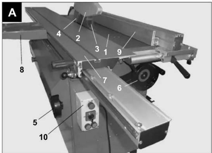
Saw (Fig. A)
- Sawing/milling machine table
- Saw – protective hood
- Saw blade
- Splitting wedge
- Saw inclination setting
- Saw height adjustment
- Carriage
- Table support
- Longitudinal stop
- Saw/milling machine switchbox
Milling machine (Fig. B)
- (A) Saw/milling machine switchbox
- Protection and stop attachment
- Lateral and vertical clamping device
- Adjustable milling stops
- Height adjustment of milling machine
- Blocking lever of the height adjustment
- Emergency-stop switch
Slide carriage for sawing and trunnion cutting (Fig. B)
- Carriage
-
Small delivery table
-
Cross-sectional stop
- Permanently clamping lever
Tool and resources (Fig. D)
Slide rod
Slide handle
Detaching pin for saw blade replacement
Box wrench for saw blade
Open-end wrench for milling machine change
Allan wrench 4/5/6 mm
Open-end wrench 10/13/17 mm
Residual risks
Circular saw (A)
The circular saw is designed for operations on solid wood or derived wood materials. It is ideal for longitudinal and format as well as bevel cuts. Firewood and roundwood should not be cut. Only hard metal covered saw blades that correspond to the Directive EN 847-1 should be used. Damaged saw blades must be replaced immediately.
Table inserts with lined kerfs must be replaced immediately. Please note that moving the wood pieces on the machine table involves the risk of physical injury.
The use of tools made of HSS steel is prohibited. Connect vacuum cleaner
Milling machine (B)
Check before each start whether the tool can
rotate freely.
Always move the workpiece against the direction of rotation. Never work with free hands,
always use a stop or clamping device.
Use slide rod for small tools.
Do not exceed the specified rotary speed.
Connect vacuum cleaner.
All installation and retro-fitting jobs must be performed after disconnecting the power plug.
Residual risks may occur despite all preventive measures, such as e.g.:
Injuries due to exposed tool or during tool change.
Clothes getting entangled in moving machine
parts or the tool. Getting crushed under workpiece guides and moving machine parts.
Injuries due to flying tool components after a tool suffers breakage.
Injuries (suffered) due to
flying workpiece parts.
Risk of fire from flames or heat radiation. Risk
when working on the electrical system. Inhalation of dust or poisonous vapours.
Transport
Transport protection: Wood lining
Delivery: Machine mounted on wood pallet
Caution: Collision or heavier loads must be
avoided, these can lead to damages to the machine and to disturbances in the settings.
Unpacking
Unpack the machine preferably in the room in which it will be operated
Deposit the machine with a crane at the provided place
Tie ropes only at the specified positions
Caution: Do not lift the machine by the
tables
Disposal of packaging material
The packing protects the machine from transport damages.
The packaging material can be recycled, and can be reused in the waste management cycle. Packaging components such as films, plastic and plastic bags can be dangerous for children.
There is risk of suffocation.
Keep the packaging components outside the reach of children and dispose of them as fast as possible
Installation / Operation
Attention: Before operation, be sure to fix the machine on level concrete ground and start the dust exhaust system first.
The resistance of the hoses fixed shall be less than 1000000 ohm
Installation of the slide table
Unpack the slide table and put it
on a table/workbench.
Remove the two nuts from the screws mounted on the bottom side of the slide table, and keep them at a safe place. (will be required for subsequent installation)
Fig. E1
Take the table out and remove the plastic flap (1) (do this on
both sides)
Fig. E2, E3
The stops (2, 3) for the slide table are already set at the factory
Just place the table on the frame of the machine (ideally with 2 persons).
Pull the Allen screw (4) softly with the help of the wrench (on both sides), move the table towards the Stop screws (2). You may now tighten the Allen screws (4).
Fig. E4
Now screw the nuts that you removed from the table at the start on the bolt of the table and tighten them uniformly
As final control, place a straight rod on the slide table, and check the surface of the machine table. Ideally, the slide table is a couple of one-tenth millimetres higher than the machine table
Installation and operation of the saw
1.0 Circular saw (A)
A Saw blade
B Splitting wedge
C Protective hood
D Longitudinal stop
E Guide bar of longitudinal stop
F Height adjustment of saw blade
G Oblique cutting adjustment
H Switchbox
For technical packaging reasons, your machine is not fully assembled.
- Open the box and remove the package components
• Take out the attached individual parts.
Caution: Disconnect the power plug before performing adjustment and mounting jobs
Installation of splitting wedge and protective hood Fig. A1 and A2
Unlock the carriage (A) and pull it back to the stop, slide back the safety guard (B)
- Turn the wheel for the height adjustment to the highest position of the saw blade.
- Detach the screw on the terminal block (C) and insert the splitting wedge (D) between the metal plate and the terminal block
- Adjust the height of the splitting wedge such that the gap between the splitting wedge and saw teeth along the curve of the saw blade is exactly the same and is not more than 5 mm.
- Tighten the screw to keep the splitting wedge at its place and position.
Mounting and removal of the saw blade guard, Fig. A3
- Loosen the tommy screw (F) to remove the protective device (E), then pull out the guard.
- To re-install the protective device, put it on the splitting wedge such that the screw fits into the slot of the splitting wedge.
- Push the protective device such that the screw fits into the recess of the slot.
- Tighten the tommy screw adequately, so that the protective device rests on the table plate, but raises itself if the workpiece is pushed against the saw blade. Please note: After cutting the workpiece, the saw blade guard must return to its resting position.
- Connect the hose (G) between the outlet of the protective device and one of the suction nozzles.
Fastening the suction hose Fig. A 3.1
To keep the saw table free, the support of the suction hose is mounted laterally on the frame of the planing table
Caution: To avoid contact with the saw blade, the saw blade guard must always be in the working position. It should lift itself on the workpiece during the sawing operation.
Saw blade change Fig. A1, A2, A3 and A4 Disconnect the power plug.
Unlock carriage (A) and move it back up to the stop
Remove the protective hood
Slide back the safety guard (B)
Turn saw blade till the locking pin (H) engages
Detach screw, remove flange and saw blade Exercise caution as there is risk of physical injury
Clean the supporting surfaces before the insertion
Replace the saw blade, (pay attention to the correct running direction)
Place the flange and tighten the screw
Remove the locking pin
Readjust the splitting wedge if necessary (distance 3 - 5 mm)
Slide the safety guard on again till the limit switch engages
Place the protective hood again and tighten it. Move the carriage back to the starting position till it engages
Adjustment of the longitudinal stop Fig. A5, A6, and A7
Introduce the guide rail (I) in the saw table (K) and fasten it with 2 tommy screws (L)
Insert the longitudinal stop (M) with the guide carriage and exact setting into the guide rail and clamp tightly. Position the stop on the saw blade and fix on "0".
The stop (N) can be installed at the left or right of the saw blade.
Comment: To ensure an exact cut, check the parallel position of the longitudinal stop and readjust if necessary.
Height adjustment of cut Fig. A8
Loosen clamping screw (U), adjust the cutting height with the handwheel (O), and tighten the clamping screw again.
Adjustment of oblique cut Fig. A8
Loosen clamping lever (P), adjust the desired degree count with the lateral handwheel (R) on the scale (S), and tighten the clamping lever again.
ON and OFF switch Fig. A8
Each activation of the switch allows the start of its own function - setting the master switch (T) to the sawing mode (see icons on switch box)
Green button Activate
Red button Deactivate
In case of danger, lateral Emergency-Stop switch
Caution: To start a function, one must unlock the stop switch without fail.
Working on the circular table saw
Use only fault-free and well sharpened saw blades. Check to ensure that the splitting wedge and protective hood have stable bases. Adjust the protective hood according to the workpiece thickness
Move the workpiece with both hands, use slide rod without fail in the area of the saw blade and push the workpiece up to the rear of the splitting wedge
Lock long workpieces to prevent tilting over at the end of the cutting operation.
Installation and operation of the milling machine
2.0 Milling machine (B)
A Milling machine protection
B Stop bar
C Guide bar
D Press protection
E Height adjustment with scale
F Spindle clamping
G Carriage
H Cross sectional stop with clamping unit
I Small delivery table
K Vacuum suction nozzle
L Tommy screws
M Machine table
Caution: Disconnect the power plug before performing adjustment and retrofitting jobs.
Installation of milling machine guard Fig. B 1
Take saw blade to the lowest position.
Remove the table insertion rings.
Position the milling machine guard (A) on the machine table (M) and install in the existing threaded holes with 2 tommy screws (L). Ensure that the milling machine guard is aligned parallel to the table.
Installation of the tool Fig. B 2 and B 3
Loosen the clamping screw (P) on the milling machine guard (A) and push it inwards, detach the tommy screw (N) and tilt the press protection (D) upwards. Tighten the tommy screws again to prevent toppling. (Fig. 2)
Open the spindle screw (N) with the Allen wrench and resist it with the open-end wrench (Fig. 3)
Place the tool on the spindle, keeping the distance between the tool and the bearing shell as small as possible, and pay attention to the direction of rotation of the tool.
To mount the tool effectively, the top-most ring
with the pin must be inserted into the groove of
the spindle. It must protrude from the spindle shaft by at least 5 mm.
Tighten the tool with the spindle screw and the Allen wrench, and resist it with the open-end wrench (Fig. 3)
Important: When the tools are lowered, keep the passage opening between the tool and the table insertion rings as narrow as possible.
Height adjustment of the spindle Fig. B 4
Loosen clamping screw (F),
Adjust the milling spindle with the hand wheel (E)
Tighten clamping screw (F) again
Note: After setting the milling spindle always clamp it to avoid vibrations and displacement of the spindle.
Adjusting speed Fig. B 5 and B 6
Loosen the knurled screw (1) on the viewing doors (2) and open the doors
Loosen the permanently clamping lever (3) and release the V-belt
Move the V-belt (4) according to rotary speed (depending on material and tool)
Stretch V-belt, tighten tommy screw
Shut the doors, turn the knurled screw up to the end (for safety)
Working with the milling machine
Correct setting up of machine saves time and is the precondition for safe jobs.
Selection of tool ( feed type, material of workpiece)
Checking tool (status of cutting and contact surfaces)
Install tool in the correct direction of rotation Cutting height and depth to be installed only when machine not in operation
Bring protective device and set the operation accordingly
Tighten all connections for safe working
Always perform sample milling with the protective device on
Perform milling only with rebound protection
Always wear ear protection during stay
ON and OFF switch Fig. A 8
Each ON switch allows the start of its own function
Set master switch (T) in the milling mode (see icons on the switch box)
Green button - Activate
Red button - Deactivate
In case of danger, press lateral Emergency-Stop switch
Caution: To start a function, one must unlock the stop switch without fail.
Slide carriage Fig. B 7
The slide carriage is fully installed.
To unlock, pull out the button (5) laterally on the table, rotate 14 turn to the right and re-engage.
Delivery table Fig. B 8
Install table (6) if necessary, laterally with 2 tommy screws.
Slide carriage with clamping device and angle setting Fig. 8
Introduce angle stop (7) into the groove of the slide table with the guide bar and tighten with the turning handle (9).
For angle settings, loosen the tommy screws (10), set angle and tighten again.
Place the tool clamp (11) in the opened state over the workpiece, tighten the clamping screw (12) and clamp the workpiece with the eccentric lever (13).
Accessories
Cross table with telescopic arm....Art. Nr. 1902103701
Pin cutting device....Art. Nr. 1902403702
Error search plan
GB
| Error Possible cause Remedy | ||
| Saw | ||
| Machine vibrates | Clamping lever for height adjustment is not screwed tightly | Tighten clamping lever |
| Tool is not screwed tightly Tighten tool | ||
| Unclean cuts / wood burns Tool is blunt Use sharp tools only | ||
| Tool is not installed correctly Check correct installation of the tool | ||
| Fast wear and tear of tool | Tool is not sharpened correctly | Have the tool re-sharpened correctly / install new tool |
| Covered wood (cement, sand, nails) Use clean wood only | ||
| Motor heats up (one can no longer touch it with bare hands, it switches off constantly) | Different causes possible Get it checked by an electrician | |
| Machine stops Feed is too fast Reduce feed | ||
| Tool is blunt Use sharp tools only | ||
| The wood is lifted high by the rear part of the saw blade | Longitudinal stop is not parallel | Readjust longitudinal stop |
| Splitting wedge not in adjustment or sewing is too weak | Readjust splitting wedge | |
| Height adjustment of the spindle is stiff | Threaded rod, toothed wheels, slide reals are polluted | Clean and lubricate components |
| Clamping lever is not loosened Check and loosen clamping lever | ||
| Milling machine | ||
| Machine vibrates | Clamping lever for height adjustment is not screwed tightly | Tighten clamping lever |
| Tool is not screwed tightly Tighten tool | ||
| Unclean cuts / wood burns Tool is blunt Use sharp tools only | ||
| Tool is not installed correctly Check correct installation of the tool | ||
| Fast wear and tear of tool | Tool is not sharpened correctly | Have the tool re-sharpened correctly / install new tool |
| Covered wood (cement, sand, nails) Use clean wood only | ||
| Motor heats up (one can no longer touch it with bare hands, it switches off constantly) | Different causes possible Get it checked by an electrician | |
| Machine stops Feed is too fast Reduce feed | ||
| Tool is blunt Use sharp tools only | ||
| Height adjustment of the spindle is stiff | Threaded rod, toothed wheels, slide reals are polluted | Clean and lubricate components |
| Clamping lever is not loosened Check and loosen clamping lever | ||
text_image
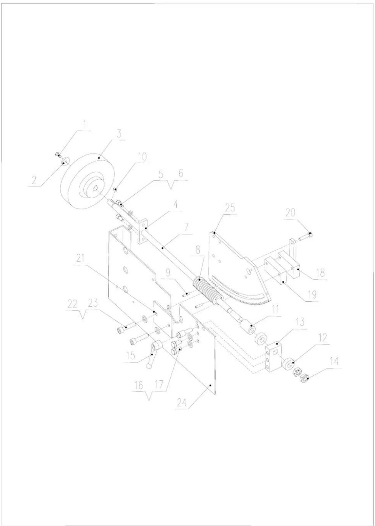
Technical schematic diagram of a mechanical assembly with numbered components for identification.TAV. 1.1

text_image
Technical schematic diagram of an industrial machine with numbered components and labeled partsTAV. 1.1.10 / TAV. 1.1.25
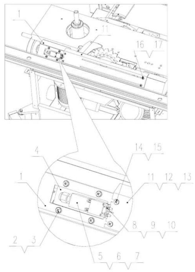
text_image
Technical diagram of a mechanical assembly with numbered components and labeled parts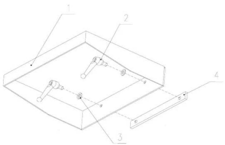
text_image
Technical diagram of a mechanical assembly with labeled components 1, 2, 3, and 4TAV. 1.1.26.1
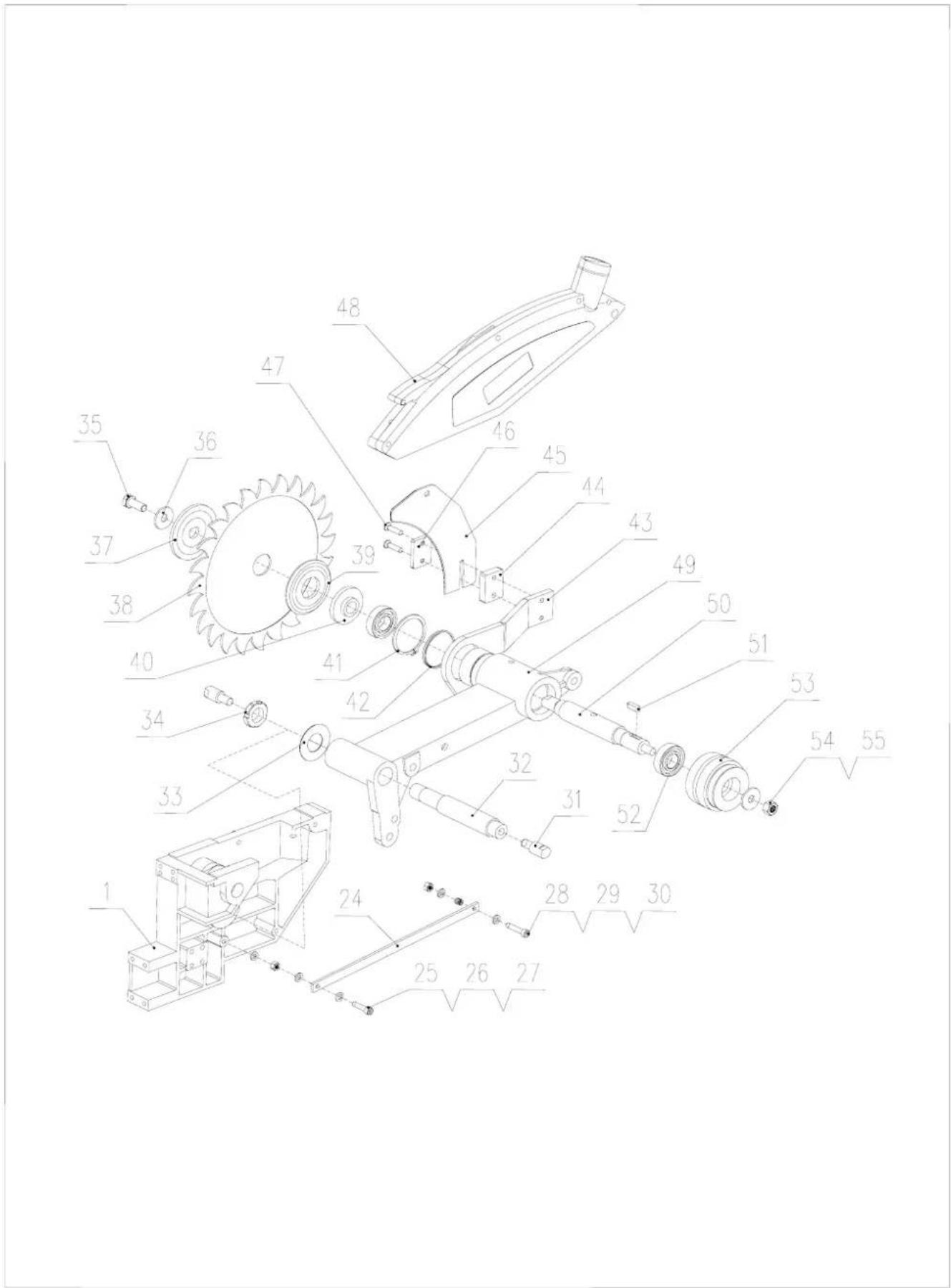
text_image
Technical diagram of a mechanical assembly with numbered components for identificationTAV. 1.1.26.2
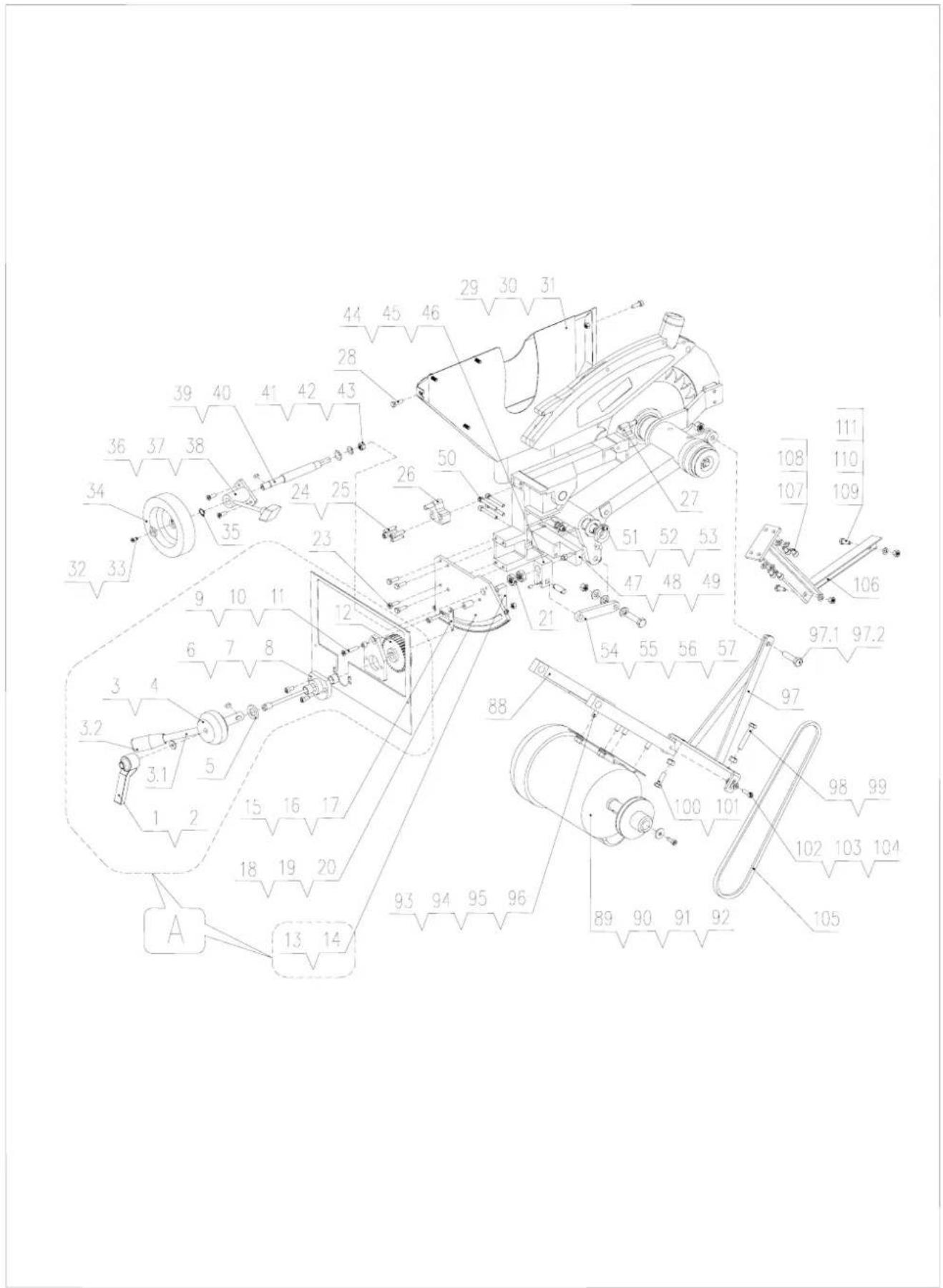
text_image
Technical diagram of a mechanical assembly with numbered components and labeled partsTAV. 1.1.26.3
text_image
Technical diagram of a mechanical assembly with numbered components for identificationTAV. 1.1.39
text_image
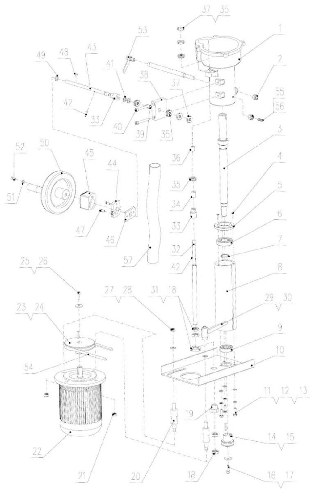
Technical schematic diagram of a mechanical assembly with numbered components and labeled partsTAV. 1.11
text_image
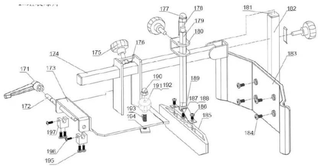
Technical diagram of a mechanical assembly with numbered components for identification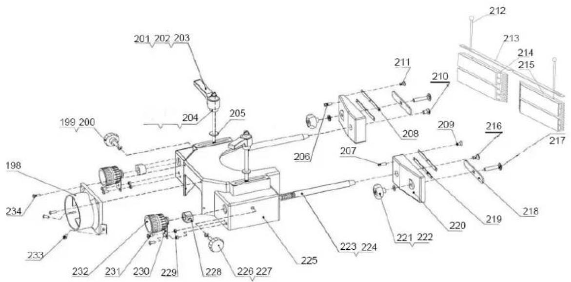
text_image
Technical diagram of a mechanical assembly with numbered components and labeled partsTAV. 1.12
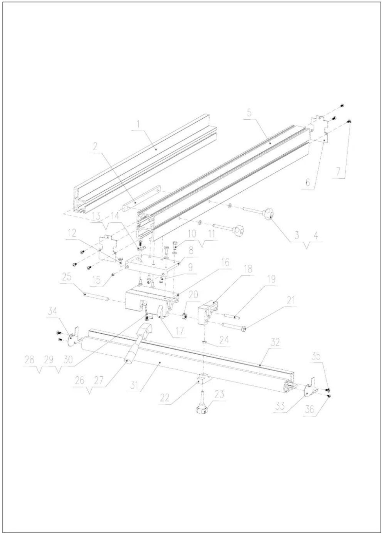
text_image
Technical schematic diagram of a mechanical assembly with numbered components for identification.TAV. 1.13
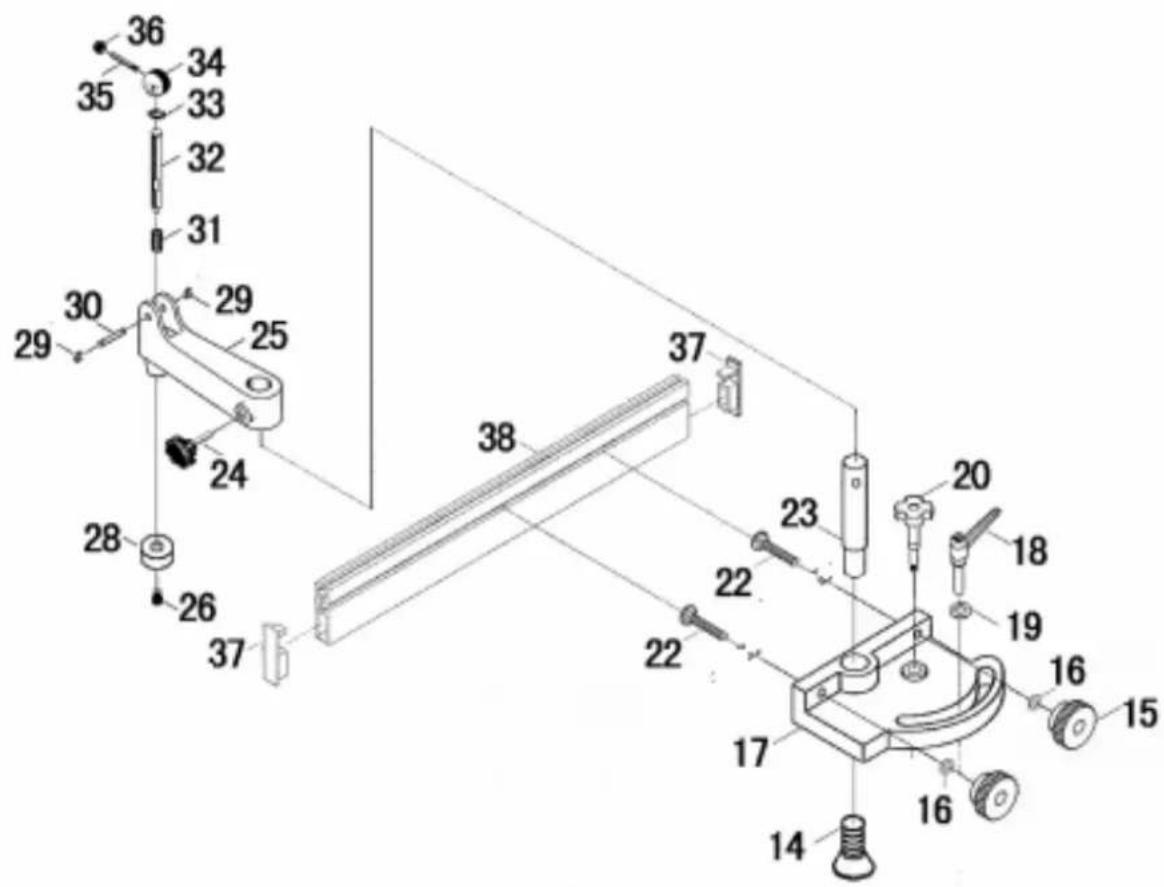
text_image
Technical diagram of a mechanical assembly with numbered components and labeled partsTAV. 1.14
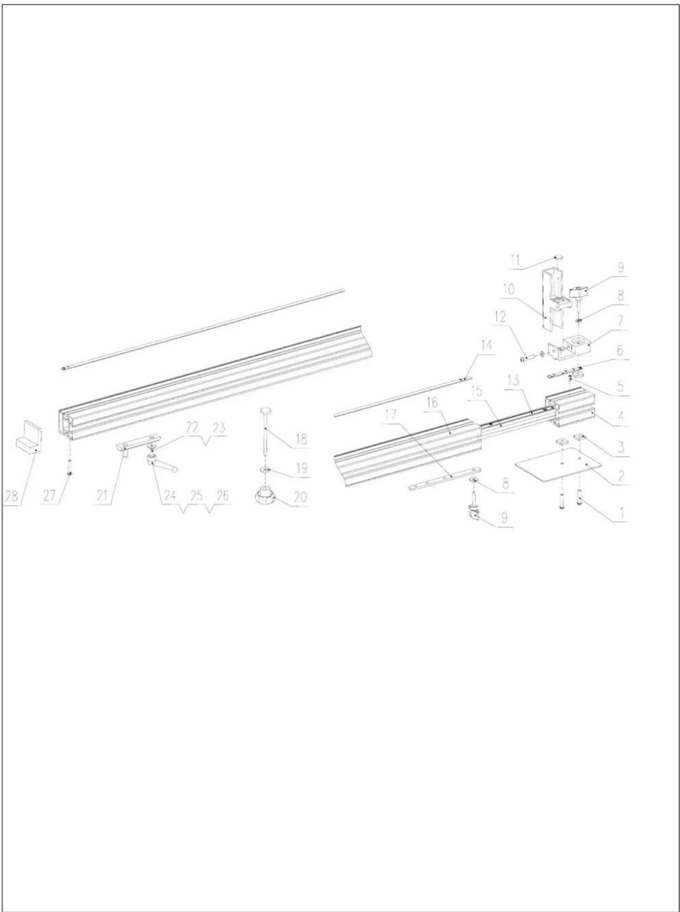
text_image
Technical diagram of a mechanical assembly with numbered components for identificationTAV. 1.15
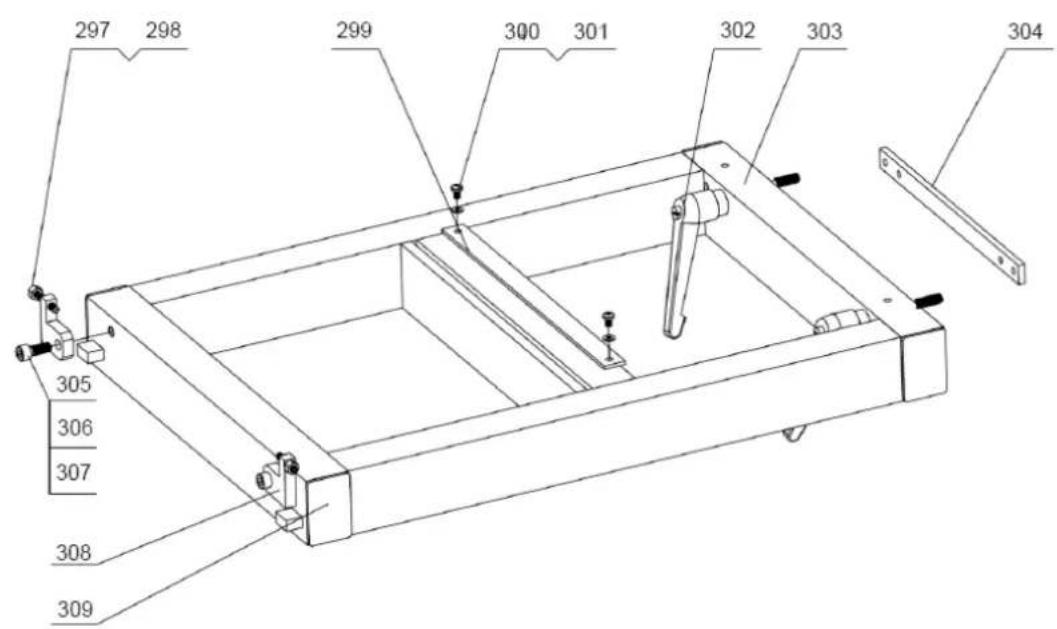
text_image
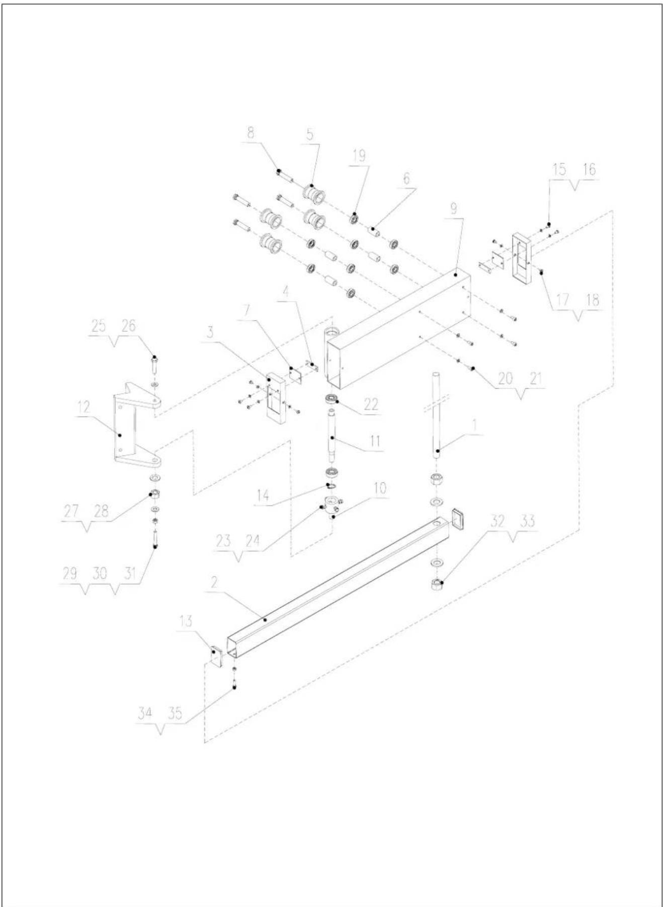
297 298 299 300 301 302 303 304 305 306 307 308 309TAV. 1.16
text_image
Technical diagram of a mechanical assembly with numbered components and exploded view| 2014/29/EU | 89/686/EC_96/58/EC | ||
| X 2014/35/EU | X 2006/42/EC | ||
| 2006/28/EC | Annex IVNotified Body:Notified Body No.:Reg. No.: | ||
| 2005/32/EC | |||
| X 2014/30/EU | 2000/14/EC_2005/88/EC | ||
| 2004/22/EC | Annex V | ||
| 1999/5/EC | Annex VINoise: measured L_WA = xx dB(A); guaranteed L_WA = xx dB(A)Notified Body:Notified Body No.: | ||
| 2014/68/EU | 2004/26/EC | ||
| 90/396/EC | Emission. No: | ||
| X 2011/65/EU | |||
Standard references: EN 848-1, EN 940, EN 60204-1, EN 1870-1
Subject to change without notice
Documents registar: Stefan Hartinger Günzburger Str. 69, D-89335 Ichenhausen
DE

Nur für EU-Länder.
Only for EU countries.
Do not dispose of electric tools together with household waste material! In observance of European directive 2012/19/EU on wasted electrical and electronic equipment and its implementation in accordance with national law, electric tools that have reached the end of their life must be collected separately and returned to an environmentally compatible recycling facility.
FR
Apparent defects must be notified within 8 days from the receipt of the goods. Otherwise, the buyer's rights of claim due to such defects are invalidated. We guarantee for our machines in case of proper treatment for the time of the statutory warranty period from delivery in such a way that we replace any machine part free of charge which provably becomes unusable due to faulty material or defects of fabrica-
tion within such period of time. With respect to parts not manufactured by us we only warrant insofar as we are entitled to warranty claims against the upstream suppliers. The costs for the installation of the new parts shall be borne by the buyer. The cancellation of sale or the reduction of purchase price as well as any other claims for damages shall be excluded.