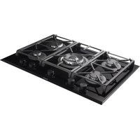
PGA-4371 - Cooker Pando - Free user manual and instructions
Find the device manual for free PGA-4371 Pando in PDF.


| Product type | Built-in gas hob |
| Brand | Pando |
| Model | PGA-4371 |
| Number of burners | 5 (1 ultra-rapid, 1 rapid, 2 semi-rapid, 1 auxiliary) |
| Total power | 10.95 kW (natural gas G20) |
| Power supply | Gas: natural G20 (20 mbar), butane G30 (28-30 mbar), propane G31 (37 mbar); Electric: 220-240 V~, 50/60 Hz |
| Dimensions (W x D x H) | 860 x 510 x 48 mm |
| Cutout dimensions (W x D) | 830 x 480 mm |
| Weight | Approximately 12 kg |
| Surface material | Ceramic glass |
| Ignition type | Built-in electric spark ignition |
| Safety device | Safety thermocouple (automatic shut-off in case of flame extinction) |
| Gas connection | 1/2" male conical |
| Electrical connection | Cable H05 RR-F 3x0.75 mm², standard plug |
| Appliance class | Category II2H3+ (natural gas and butane/propane) |
| Maximum ambient temperature for walls | 90 °C |
| Functions | Electric ignition, flame regulation, high-efficiency burners |
| Maintenance | Clean with soapy water and a nylon brush; avoid abrasives and steam cleaners |
| Provided accessories | Enamelled grills, spare nozzles for gas conversion |
| Warranty | 3 years |
Frequently Asked Questions - PGA-4371 Pando
User questions about PGA-4371 Pando
0 question about this device. Answer the ones you know or ask your own.
Ask a new question about this device
Download the instructions for your Cooker in PDF format for free! Find your manual PGA-4371 - Pando and take your electronic device back in hand. On this page are published all the documents necessary for the use of your device. PGA-4371 by Pando.
USER MANUAL PGA-4371 Pando
natural_image
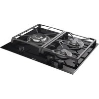
Close-up of a Pando gas stove with four stoves and control knobs (no visible text or symbols on the stove itself)Pando integralcooking
PGA-4261
PGA-4371
PGA-4492
Certificate of registration of carbon footprint, offsetting and CO2 absorption projects of the Ministry for Ecological Transition and Demographic Challenge (MITERD).
The Global Kitchen Partner
natural_image
Symbol of a waste bin with no text or labels, crossed by diagonal lines and a solid rectangle below (no text or symbols present)
TRATAMIENTO DEL RESIDUO
natural_image
Diagram showing a brick wall corner with a wall-mounted component and an arrow pointing to a marked point (*) (no text or symbols present)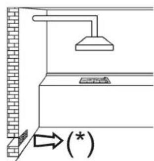
USO DE LA PLACA
QUEMADORES
natural_image
Two simple line drawings of a cooking pot with a wavy base and heating elements, no text or symbols present.natural_image
Line drawing of a hand using a tool to clean or inspect a circular component (no text or symbols)natural_image
Simple line drawing of a cooking pot and a heating box with no text or symbols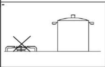
natural_image
Simple line drawing of a cooking pot and a stand (no text or symbols)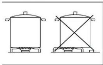
natural_image
Two simple line drawings of a cooking pot and a stand (no text or symbols)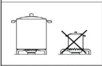
natural_image
Two simple line drawings of cooking pots with no text or symbols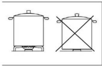
natural_image
Two simple line drawings of a cooking pot and a cooking pot with crossed-out handles (no text or symbols)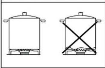
natural_image
Two simple line drawings of a cooking pot with a horizontal stirrer and cross-shaped heating element (no text or symbols)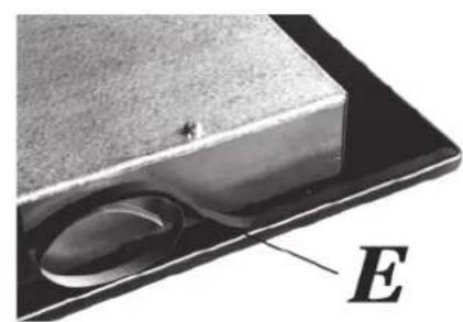
natural_image
Close-up of a metallic object with a circular indentation and a labeled point E (no text or symbols on the object itself)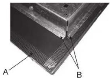
natural_image
Close-up of a metallic panel with labeled points A and B, showing internal structure (no text or symbols beyond labels)natural_image
Close-up of a mechanical component with labeled point A, showing a circular housing and central hub (no text or symbols beyond label)CÓMO SUSTITUIR PIEZAS DE LOS QUEMADORES
natural_image
Close-up of a mechanical component with a tool and labeled point V, no readable text or symbols present.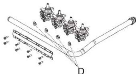
natural_image
Technical line drawing of a pipe assembly with multiple valve components and a labeled component D (no text or symbols present)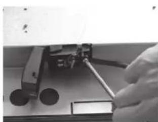
natural_image
Close-up of a hand using a tool to adjust or install a mechanical component (no visible text or symbols)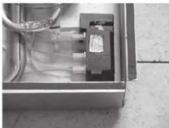
natural_image
Interior view of an open electrical enclosure with visible wiring and components (no text or symbols)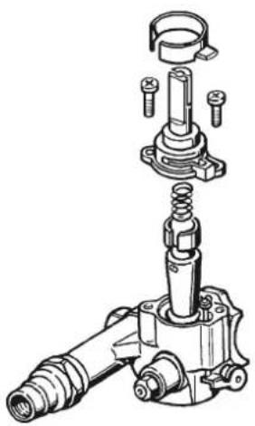
natural_image
Technical illustration of a mechanical assembly with exploded view (no text or labels)natural_image
Symbol of a trash bin crossed out by two crossed lines, with no text or labels present.
natural_image
Two simple line drawings of a cooking pot with a wavy base and heating elements, no text or symbols present.natural_image
Line drawing of a hand using a tool to adjust or install a circular component (no text or symbols present)POUPANÇA DE ENER- GIA E CUIDADOS COM A PANELA
natural_image
Simple line drawing of a cooking pot and a heating box with no text or symbols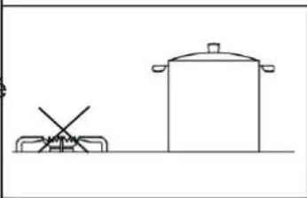
natural_image
Simple line drawing of a cooking pot and a cooking utensil (no text or symbols)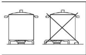
natural_image
Two simple line drawings of a cooking pot and a stand (no text or symbols)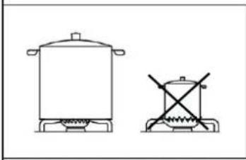
natural_image
Two simple line drawings of cooking pots with no text or symbols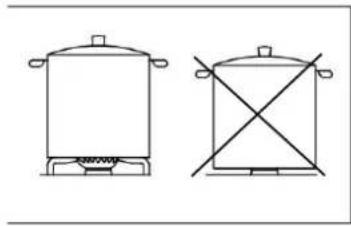
natural_image
Two simple line drawings of a cooking pot and a crossed-out box (no text or symbols)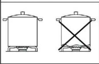
natural_image
Two simple line drawings of a cooking pot with a horizontal crossbar, shown from different angles (no text or symbols)natural_image
Technical line drawing of a mechanical assembly with two labeled components (1 and 2), no text or symbols present.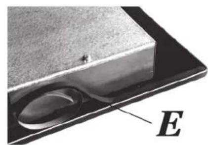
natural_image
Close-up of a metallic object with a circular indentation and a labeled point E (no text or symbols on the object itself)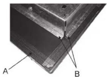
natural_image
Close-up of a metallic panel with labeled points A and B, showing internal structure (no text or symbols beyond labels)natural_image
Close-up of a mechanical component with a labeled section A, showing internal parts and mounting holes (no text or symbols beyond label)COMO SUBSTITUIR AS PEÇAS DO QUEIMADOR
natural_image
Close-up of a mechanical component with a tool and labeled 'V' pointing to a hole (no readable text or symbols beyond label)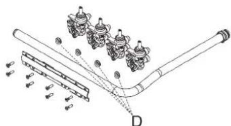
natural_image
Technical diagram of a mechanical assembly with pipes and components, no visible text or symbols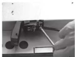
natural_image
Close-up of a hand using a tool to adjust or install a mechanical component (no visible text or symbols)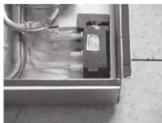
natural_image
Interior view of an open electrical enclosure with visible wiring and a black component (no text or symbols)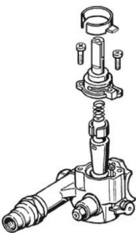
natural_image
Technical illustration of a mechanical assembly with exploded view (no text or labels)natural_image
Symbol of a trash bin crossed out by two diagonal lines, no text or labels present
TRAITEMENT DES DÉCHETS
REPLACEMENT DES PIÈCES....86
• COMMENT REMPLACER UN INJECTEUR 86
• COMMENT REMPLACER LES PIÈCES DU BRÛLEUR 87
INFORMATIONS TECHNIQUES 89
AVERTISSEMENTS DE SÉCURITÉ
natural_image
Diagram showing a brick wall corner with a wall-mounted component and an arrow pointing to a marked point (*) (no text or symbols present)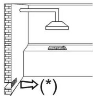
gaz, contactez le service d'assistance technique de Pando.
natural_image
Line drawings of two cooking pots with heating elements, no text or symbols presentnatural_image
Line drawing of a hand using a tool to clean or inspect a circular component (no text or symbols)ÉCONOMIE D'ÉNERGIE ET MAINTENANCE DES POÊLES
natural_image
Simple line drawing of a cooking pot and a square with a crossed-out pan (no text or symbols)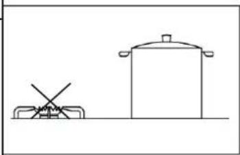
natural_image
Simple line drawing of a cooking pot and a cooking pot with a crossed handle (no text or symbols)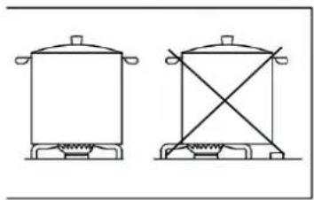
natural_image
Two simple line drawings of a cooking pot and a stand (no text or symbols)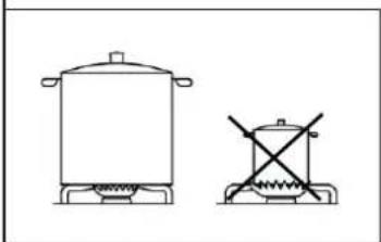
natural_image
Simple line drawing of two cooking pots with no text or symbols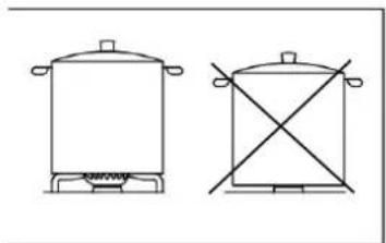
natural_image
Two simple line drawings of cooking pots with no text or symbols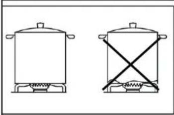
natural_image
Two simple line drawings of cooking pots with steamers, one crossed out by a diagonal line (no text or symbols)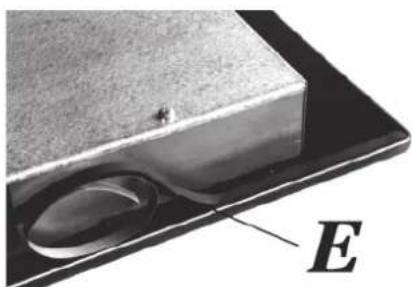
natural_image
Close-up of a metallic object with a circular indentation and a labeled point E (no text or symbols on the object itself)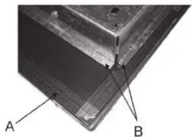
natural_image
Close-up of a metallic panel with labeled points A and B, showing internal structure (no text or symbols beyond labels)REEMPLACEMENT DES PIÈCES
COMMENT REMPLACER UN INJECTEUR
natural_image
Close-up of a mechanical component with labeled point A, showing internal gears and mounting holes (no text or symbols beyond label)COMMENT REMPLACER LES PIÈCES DU BRÛLEUR
natural_image
Close-up of a hand using a tool to insert a mechanical component, labeled 'V' (no text or symbols on the object itself)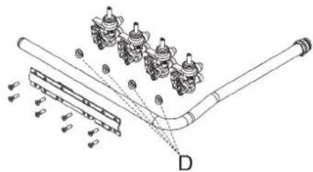
natural_image
Technical line drawing of a pipe assembly with multiple valve components and a labeled component D (no text or symbols present)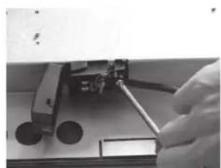
natural_image
Close-up of a hand using a tool to adjust or install electronic components (no visible text or symbols)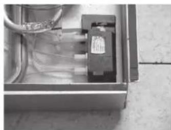
natural_image
Interior view of an electrical enclosure showing wiring and a component (no visible text or symbols)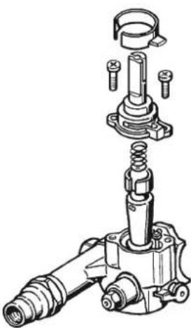
natural_image
Technical illustration of a mechanical assembly with exploded view (no text or labels)Pando reserves the right to change or cancel any measures of the articles in the manual without prior notice, without affecting the essential characteristics of functionality and safety, and is not responsible for any errors or omissions that may occur in the manual.
Technical specifications valid except for typographical errors, omission, or printing.
The images and content of this manual are the exclusive property of Pando - INOXPAN S.L., and any appropriation of images and total or partial reproduction without prior written authorization is strictly prohibited.
THE IMAGES SHOWN IN THIS MANUAL ARE NOT CONTRACTUAL.
Pando's Technical Management reserves the right to modify, alter, or improve the technical drawings displayed in this manual without prior notice.
The paper version of this manual cannot be updated in real-time, to ensure the latest version of your product's instructions, we recommend consulting the digital version at www.pando.es
First of all, we would like to thank you for the trust you have placed in our company by purchasing one of our products.
For purchasing one of our products. We are sure that you have made the right decision.
At Pando, not only do we offer top quality products, but we also have a large team of professionals who will help you and advise you on any queries you may have during installation or operation.
To get to know us better, we invite you to visit our website (www.pando.es) where you can see our full range of products with the most up to date commercial and technical information.
Here you will find a wide selection of Decorative Hoods; wall-mounted, ceiling-mounted, island, integrated into furniture and integrated into the hob.
This variety allows us to adapt to any style of kitchen.
We also show you our collection of essential appliances in any home.
Appliances such as our collection of high-performance Ovens and Microwaves with high performance, Induction and Gas Hobs that will help you to make the best recipes, Wine Cellars and Ageing Cellars to maintain and preserve your wines in the best conditions, Dishwashers with the most modern technology and our with the most up-to-date technology and our range of Refrigerators and Freezers with Freezers and Refrigerators for panel integration together with those for free installation.
All this under a brand with a very long trajectory of more than 40 years in the sector, which manufactures its products as a sector, which manufactures its products like a true craftsman. Bringing the best of our experience to everything we do.
We sincerely hope you have fun, experience and enjoy the comfort and capabilities of what is already your new capabilities of what is already your new kitchen ally.
Thank you
Pando team
ENVIRONMENTAL PROTECTION
The symbol on the product or its packaging indicates that this product cannot be disposed of like normal domestic waste. The product must be handed over at a collection point for recycling electrical and electronic equipment. If you ensure that this product is correctly disposed of, you will help to avoid the possible negative environmental and public health effects that could arise from incorrect disposal. For more detailed information about recycling this product, please contact your city authorities, the domestic waste service or the establishment where you purchased it. This electrical appliance is marked in compliance with European Directive 2012/19/EU on electrical and electronic appliance waste (WEEE).
COLLECTION OF HOUSEHOLD APPLIANCES
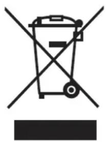
natural_image
Symbol of a trash bin crossed with no text or labels, accompanied by a horizontal line and a solid rectangle below (no text or symbols present)
WASTE TREATMENT
DISPOSAL OF THE PACKAGING. The packaging is marked with in Green Dot.
In its commitment to the protection of the environment and in compliance with the provisions of the European Directive 94/62 / EC on packaging and packaging waste and the derived Law 22/2011 on Waste and Contaminated Soil, Pando entrusts entities of social economy an Integrated Management System, responsible for the periodic collection at the consumer's home or in its vicinity of used packaging and packaging waste for subsequent treatment.
To remove all packaging materials such as cardboard, expanded polyurethane, and film, use the appropriate containers.
This ensures the correct treatment and reuse of packaging materials.
INDEX
SAFETY WARNINGS....96
DESCRIPTION OF THE COOKING PANEL....102
RECOMMENDATIONS FOR USE 103
USE OF THE DISPLAY....103
• BURNERS....103
• HOW TO USE THE BURNERS....104
CLEANING....104
- SURFACE 104
ENERGY SAVING AND PAN CARE....105
TROUBLESHOOTING....106
BEFORE INSTALLATION....107
- TECHNICAL INFORMATION FOR THE INSTALLER 107
- PLATE POSITIONING....107
DIMENSIONS OF THE PLATES....107
FITTING DIMENSIONS....108
INSTALLATION....109
- SIDE GRAPHS....109
- REAR GRAPHS 110
• CORRECT INSTALLATION OF THE PANEL 111
- IMPORTANT INSTALLATION REQUIREMENTS.... 111
- VENTILATION OF THE ROOM....111
- LOCATION AND AIRING 112
• GAS CONNECTION....112
• ELECTRICAL CONNECTIONS....113
ADJUSTING THE CONTROLS 114
- Setting the reduced flow rate....114
REPLACING PARTS 114
• HOW TO REPLACE AN INJECTOR 114
• HOW TO REPLACE BURNER PARTS 115
TECHNICAL INFORMATION......117
SAFETY WARNINGS
Read these instructions carefully. Keep the instructions and product information for later use or for future owners. Do not connect the appliance if it has been damaged during transport.
Only professional installation in accordance with the installation instructions can guarantee safe use of the appliance. The installer is responsible for perfect functioning at the installation site.
Use the appliance only:
- For cooking.
• In private homes and in a domestic environment. - Up to an altitude of 2000 m above sea level.
Do not use the appliance:
• On boats or vehicles.
- As a heater.
- With an external timer or remote control.
- Outdoors.
To change to another type of gas,
please contact Customer Service.
This appliance can be used by children aged from 8 years and above and persons with reduced physical, sensory or mental capabilities or lack of experience and knowledge if they have been given supervision or instruction concerning use of the appliance by a person responsible for their safety and if they understand the hazards involved.
Do not allow children to play with the appliance.
Cleaning and user care must not be carried out by children unless they are at least 15 years old and supervised by an adult.
Keep children under 8 years of age away from the appliance and the mains cable.
Risk of explosion!
A gas leak can cause an explosion.
IF YOU FEEL A SMELL OF GAS OR IF THERE IS A DAMAGE TO THE GAS SYSTEM:
- Immediately turn off the gas supply or close the valve on the gas
cylinder.
- Immediately extinguish open fires and cigarettes.
- Do not operate light switches and appliance switches again.
- Do not pull out any plugs from the socket.
- Do not use a landline or mobile phone near the appliance.
- Open the window and ventilate the room thoroughly.
- Call Technical Support or the gas supply company.
A gas leak can cause an explosion. Small amounts of gas can accumulate and ignite over a long period of time.
- If the appliance is not used for long periods of time, close the safety valve on the gas supply.
A gas leak can cause an explosion. If the liquid gas cylinder is not in an upright position, liquid propane/butane can flow into the appliance, which can cause a naked flame on the burners. Over time, the components may become damaged and leak, so that gas may escape.
Always place liquid gas cylinders in an upright position.
Risk of poisoning!
The use of a gas cooker leads to the formation of heat, moisture and combustion products in the room where it is installed.
- Ensure adequate ventilation of the cooker, particularly during operation of the appliance.
- In case of intensive and prolonged use of the appliance, ensure additional ventilation to lead the combustion products safely to the outside, e.g. set a higher power level with an existing mechanical ventilation device and, at the same time, ensure that fresh air enters the room in which the appliance is installed.
To install an additional ventilation device, contact qualified personnel.
Risk of fire!
Leaving the hob unattended when cooking with oil or fat can be dangerous and can cause fires.
- Never leave oils and fats unattended.
- Never try to put out a fire with water. You must switch off the appliance and then cover the flames with a fire blanket or fire blanket.
The appliance becomes very hot.
- Do not place flammable objects on or near the hob.
- Never store objects on the hob.
The appliance becomes hot.
- Do not store flammable objects or aerosols in the drawers directly below the hob.
- Do not store or use flammable objects such as aerosols or cleaning agents under or near the appliance.
Hob covers can cause accidents, e.g. due to overheating, ignition or falling material fragments.
- Do not use any hob covers.
Gas burners without cooking containers generate a large amount of heat during operation. A hood, if present, could be damaged or catch fire. - Use gas burners only with cooking
vessels placed on top of them.
When the appliance becomes very hot, textiles and other objects in the vicinity can catch fire.
- Keep textiles (e.g. clothing or curtains) away from the appliance, clothing or curtains) away from the flames.
- Never touch the flames.
- Do not store flammable objects (e.g. tea towels or magazines) on, near or behind the appliance.
A build-up of gas can ignite and cause a fire.
- If the flame does not ignite after 10 seconds, turn the control knob to the zero position and open the door or window to the room. Wait at least one minute before relighting the burner.
- If the flame goes out unintentionally during operation, turn the control knob to the zero position. Wait at least one minute before relighting the burner.
Food may catch fire.
- The cooking process must be monitored. Short processes must be
continuously monitored.
Risk of burns!
Accessible parts can become hot during operation.
- Keep small children away from the appliance.
- Protective grids for hotplates can cause accidents.
- Never use protective grids for hot-plate grates.
Cookware reaches very high temperatures on the gas burners when empty.
- Never heat cookware when it is empty.
The appliance becomes hot during operation.
- Allow the appliance to cool down before cleaning.
Risk of electric shock!
Improper repairs are dangerous.
• Repairs and interventions on the appliance may only be carried out by qualified personnel.
- Only use original spare parts to repair the appliance.
- If the mains connection cable of
this appliance is damaged, it must be replaced by the manufacturer, the Service Centre or a qualified person in order to avoid possible hazards.
A damaged appliance or a defective mains cable is dangerous.
- Never operate a damaged appliance.
- Never pull on the mains cable to unplug the appliance.
- If the appliance or the mains cable is damaged, immediately unplug the mains cable or disconnect the fuse from the fuse box and turn off the gas supply.
- The infiltration of moisture can cause an electric shock.
- Do not use steam cleaners or high-pressure cleaners to clean the appliance.
- The insulation of the cable of an electrical appliance can melt when it comes into contact with hot components.
- Do not allow the connection cable of an electrical appliance to come into contact with hot components.
Risk of injury!
Faults or damage to the appliance and improper repairs can lead to serious dangers.
If the appliance is faulty:
- disconnect it from the mains or switch off the fuse in the fuse box, cut off the gas supply and call Customer Services.
- Repairs to the appliance and the replacement of damaged gas lines may only be carried out by qualified personnel.
- Immediately switch off all burners and any electrical heating elements and disconnect the appliance from the mains supply. Never connect a faulty appliance.
- Switch off the gas supply.
- Do not touch the surface of the appliance.
- Do not use the appliance.
When lighting the burner, sparks are produced on the spark plugs.
- Never touch the spark plugs while the gas appliance is igniting.
- If any of the controls cannot be turned or are loose, do not use it.
- Immediately call a service technician for repair or replacement in the event of a fault.
- An appliance with a broken or torn surface can cause injuries and cuts. Do not use the appliance if it has a broken or torn surface.
Risk of suffocation!
- Children could put the packaging material over their heads or roll up in it and suffocate.
- Keep the packaging material out of the reach of children.
- Do not allow children to play with the packaging.
- If children find small parts, they could inhale or swallow them and suffocate.
- Keep small parts out of the reach of children.
- Do not allow children to play with small parts.
AVOID MATERIAL DAMAGE
Heat can cause damage to adjacent
appliances or furniture. If the appliance is used for a long time, heat and moisture will be produced.
- Open a window or switch on an extractor Hood with an outlet to the outside.
- A build-up of heat can damage the appliance.
- Do not use two burners or heat sources for one pan.
- Avoid using griddles, casserole dishes or similar with the heat source on full power for a long time.
- A build-up of heat can damage the knobs.
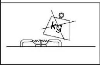
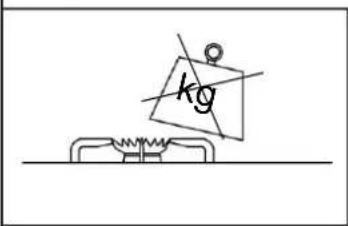
- Do not place large containers on the burners near the knobs.
- Incorrect positioning of a control knob can cause malfunctions.
- Keep the control knob in the zero position when the appliance is not in use.
DESCRIPTION OF THE COOKING PANEL
PGA-4261
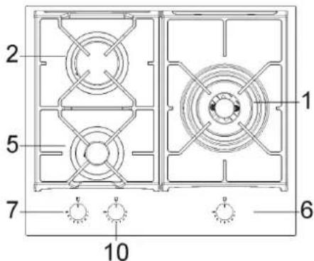
PGA-4371PGA-4492
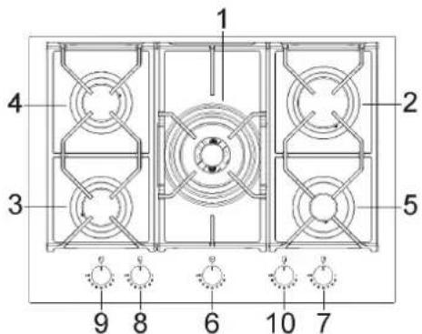
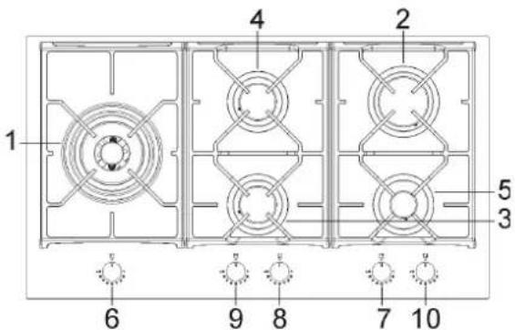
- Ultra-fast burner ∅133 mm 4000 W
- Fast burner ∅100mm 2800 W
- Auxiliary burner ∅55mm 1000 W
- Grill
- Burner control n° 1
- Burner control n° 2
- Reduced semi-fast burner ∅75mm 1400 W
- Semi-fast burner ∅75mm 1750 W
- Burner control n° 4
-
Burner control n° 3
-
Burner control n° 5 Burner control n° 2 Reduced semi-fast burner ∅75mm 1400W Semi-fast burner ∅75mm 1750W Semi-fast burner ∅75mm 1750W n° 5
RECOMMENDATIONS FOR USE
WARNING: During operation, the gas hob becomes very hot, especially in the cooking zo- nes. Keep children away from the area.
WARNING: If the glass on the hob breaks, immediately turn off all burners and electric heating elements and disconnect the power supply to the appliance. Do not touch the surface of the appliance or use it.
- In the event of a power failure, the burner can be lit with matches.
- During use, do not leave the appliance unattended and make sure that children are not in the vicinity. In particular, make sure that the handles of the pans are in the correct position and carefully control the cooking of food with oils or fats as they are easily inflammable.
- Do not use aerosols near the appliance when it is working.
- Do not scrape the pans on the glass, this could damage the surface.
- The use of pans whose diameter exceeds the perimeter of the hob is not recommended.
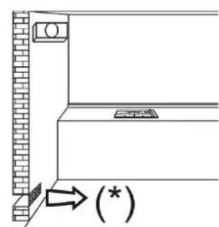
- The use of a gas cooking appliance produces heat and humidity in the room where it is installed. For this reason, it is necessary to ensure good ventilation of the space by keeping the natural ventilation opening free and activating a ventilation device such as an extractor hood or electric fan.
- If the appliance is used intensively and for a prolonged period of time, additional ventila-
tion may be necessary. In this case, you can open a window or increase the power of the mechanical suction if available.
- Do not attempt to modify the technical characteristics of the product, as this could be dangerous.
- If you decide to stop using this appliance (or replace an old model), before disposal, it is recommended that it is rendered unusable in accordance with current health and environmental pollution regulations, by removing the parts that could pose a hazard, especially for children, who could use the appliance out of use to play with it.
- Do not use the appliance when barefoot.
- The manufacturer cannot be held responsible for any damage resulting from improper, erroneous or unreasonable use.
- During and immediately after operation, some parts of the hob reach very high temperatures. Avoid touching them.
• After using the gas hob, make sure that the rotary knobs are in the closed position and close the main tap on the gas distribution line or the gas cylinder tap.
• In the event of malfunctions of the gas taps, contact the Pando technical support service.
- Do not touch the appliance with wet or damp hands or feet.
USE OF THE DISPLAY
BURNERS
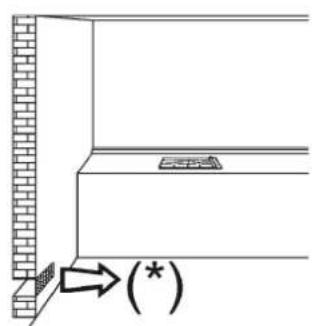
You will find a diagram indicating which burner
natural_image
Diagram showing a brick wall corner with a wall-mounted component and an arrow pointing to a marked point (*) (no text or symbols present)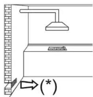
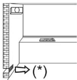
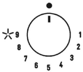
each control corresponds to on the top of each control, silk-screened on the glass. Once the gas mains or gas cylinder tap has been turned on, light the burners according to the following instructions:
• Automatic electric ignition
Press and turn the knob corresponding to the burner you wish to use to the left, turn it to the maximum position and press the knob all the way down.
- Ignition of burners fitted with safety thermocouple (flame failure)
For burners with safety thermocouple, turn the knob on the burner you wish to use to the left, turn it to the maximum position until you feel a small stop, press the knob and repeat the operation.
Once lit, keep the knob pressed for at least 10 seconds.
If the flames go out unintentionally, close the knob on the burner and wait at least 1 minute before trying to light it again.
HOW TO USE THE BURNERS
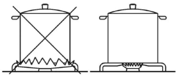
For maximum performance with minimum gas consumption:
- Use pots of the correct size for each burner.
- Once boiling has been reached, reduce the burner power to the minimum (1).
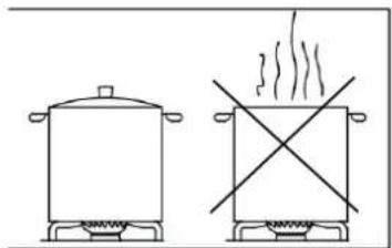
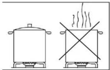
• Always use pots with lids.
• Always use pots with flat bottoms.
natural_image
Line drawings of two cooking pots with heating elements, no text or symbols present| BURNER ∅ cm | |
| Ultra-fast 24-26 | |
| Fast 20-22 | |
| Semi-fast 16-18 | |
| Semi-fast reduced | 16-18 |
| Auxiliary | 10-14 |
CLEANING
WARNING: Before cleaning your hob, disconnect it from the gas supply and the power supply.
SURFACE
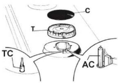
To keep the surface of the hob shiny, it is very important to wash it after each use with warm soapy water, rinse and dry it. The enamelled grids, enamelled covers and spark plugs (AC) and thermocouple sensors (TC) should also be washed.
These components should not be washed in the dishwasher
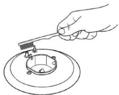
Gently clean with a small nylon brush and allow to dry thoroughly. The board and its components should be cleaned cold, without using metallic sponges, abrasive powders or corrosive sprays.
Do not allow the surfaces to remain in contact with products such as vinegar, coffee, milk, saline water or lemon or tomato juice.
WARNING: When reassembling the components:
- Check that the cracks in the burner heads are not obstructed.
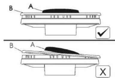
- Make sure that the enamelled caps are correctly positioned on the burner head. You can verify this by checking if the cover is perfectly
stable once in place.
- The grids must be placed on the appropriate centring pins or on the aluminium profile. Check that the stability is correct.
- If it is difficult to open or close a key, do not force it. Contact Pando Technical Support.
- Do not use steam jets to clean the appliance.
• To prevent possible ignition problems, clean the spark plugs and thermocouples thoroughly and frequently.
natural_image
Line drawing of a hand using a comb to clean or adjust a circular component (no text or symbols)ENERGY SAVING AND PAN CARE
natural_image
Simple line drawing of a cooking pot and a heating box with no text or symbols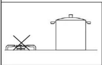
natural_image
Simple line drawing of a cooking pot and a stand (no text or symbols)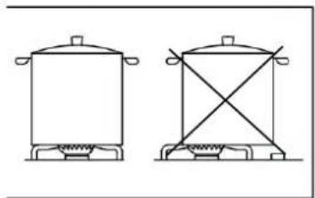
natural_image
Two simple line drawings of a cooking pot and a stand (no text or symbols)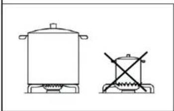
natural_image
Simple line drawing of a cooking pot and its heating unit (no text or symbols)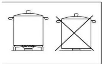
natural_image
Two simple line drawings of cooking pots: one with a lid and one with crossed-out panes (no text or symbols)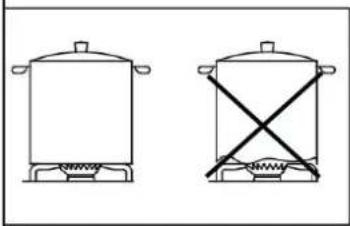
natural_image
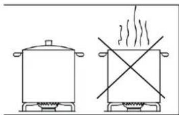
Two simple line drawings of cooking pots with steamers, one with a crossed-out X-line symbol (no text or labels)- To avoid wasting energy, do not cook without a lid or with the lid off.
- Centre the pan on the burner.
- Do not place large containers close to the controls as they may be damaged by overheating.
- Never place the pan directly on the burner. Always place it on the grates and make sure that the grates are properly positioned before use.
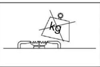
- Handle pans carefully on the hob, do not bang the hob or place excessive weight on it.
- Do not leave the fire burning after removing the pan. This could cause serious damage.
- Use the most suitable size burner for each pan. Do not use pots that are smaller than the burner, as the flame may not come into contact with the sides of the pot.
- Always use pans that have a good, flat, thick base. Deformed pots may tip over.
TROUBLESHOOTING
| PROBLEM CAUSE SOLUTION | ||
| The burner flame is uneven. | The burner crown is dirty. Clean the burner crown. | |
| The gas is not adjusted correctly. | Contact Pando Technical Service. | |
| The burner flame changes suddenly or bursts. | The burner components are not correctly assembled. | Position the burner elements correctly. |
| The flame takes too long to ignite. | The burner components are not mounted correctly. | Position the burner elements correctly. |
| The flame goes out after ignition. | You have stopped pressing the ignition wheel too soon. | Keep pressing the ignition wheel until you see that the flames keep burning. |
| Thermocouple problems. | Move the thermocouple. | |
| Contact Pando Technical Assistance Service. | ||
| The grids change colour in the cooking zone. | High temperatures or dirt have caused the colour change. | This is common and does not affect the performance of your gas hob. |
| The flame does not ignite when the wheel is pressed because the glow plugs do not emit a spark. | Problem with the spark plug or ignition wheel. | Contact the Pando Technical Assistance Service. |
| The electric ignition does not work. | Lack of electric current. | Check that the socket is connected. Check that the meter is switched on. |
| Incorrect assembly or misfiring. | Contact Pando Service. | |
| Glow plugs spark continuously. | Moisture. | Disconnect the power for 24 hours and allow the top to dry. Check that all bushings are mounted correctly. |
| Incorrect mounting or broken microphone. | Contact Pando Service. | |
BEFORE INSTALLATION
TECHNICAL INFORMATION FOR THE INSTALLER
Installation, adjustments, conversions and maintenance must be carried out by qualified personnel only.
The equipment must be installed correctly, in compliance with the standards in force and according to the manufacturer's instructions. Incorrect installation may cause damage to persons, animals or objects for which the manufacturer cannot be held responsible.
The safety devices or automatic regulation devices of the equipment during the life of the equipment may only be modified by the manufacturer or by the authorised supplier.
PLATE POSITIONING
- Remove the external packaging and the internal packaging of the various mobile components and make sure that they are intact. If in doubt, do not use the appliance and contact qualified personnel.
The packaging elements (cardboard, bags, polystyrene, nails, etc.) must not be left within the reach of children, as they can be dangerous. WARNING:
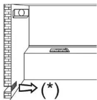
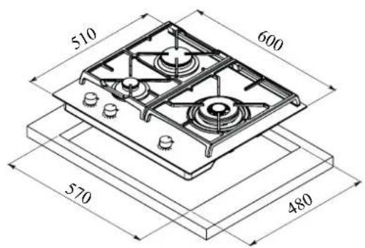
- Make an opening in the cabinet, always strictly respecting the critical distances between the surface, the side walls, the back wall and the top wall, as shown in the image.
The appliance is classified as class 3 and is therefore subject to all the regulations for such equipment.
DIMENSIONS OF THE PLATES
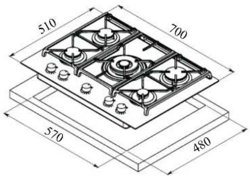
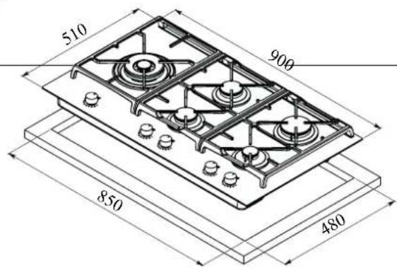
FITTING DIMENSIONS
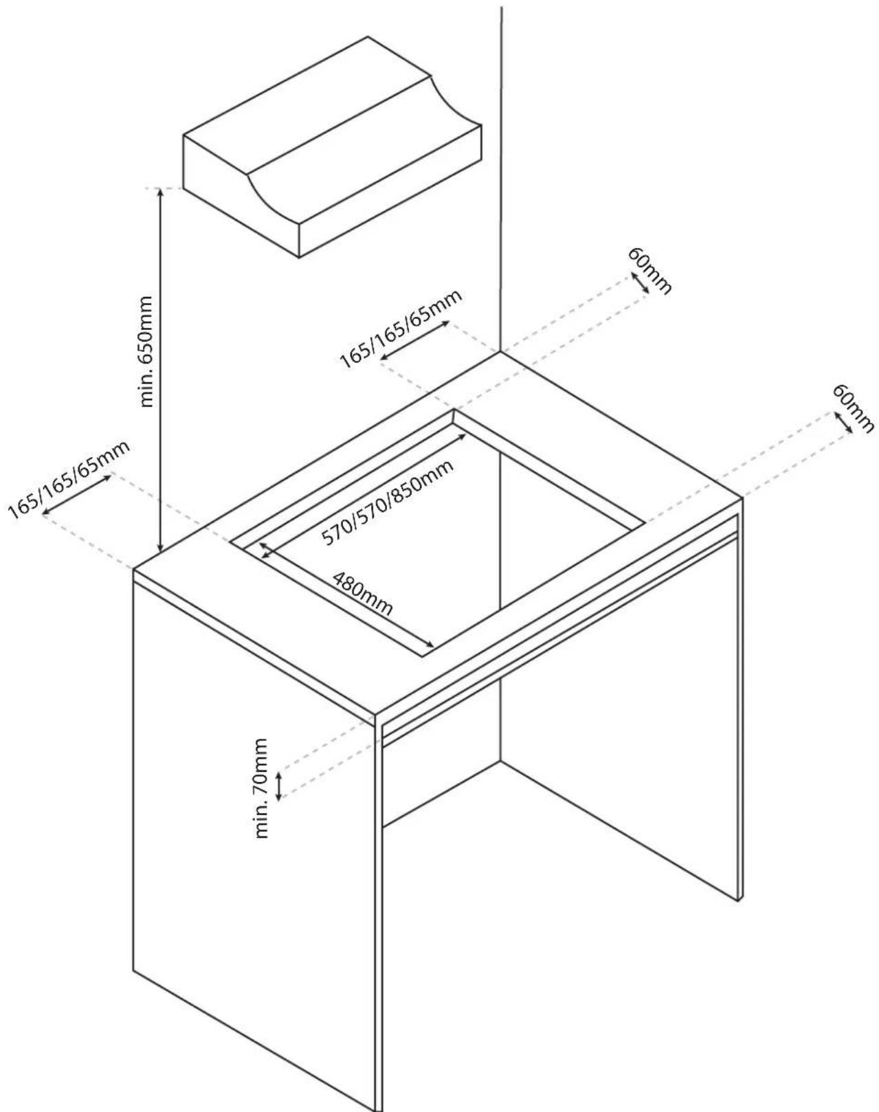
INSTALLATION
SIDE GRAPHS
REAR GRAPHS
CORRECT INSTALLATION OF THE PANEL
natural_image
Close-up of a metallic object with a circular indentation and a labeled point E (no text or symbols on the object itself)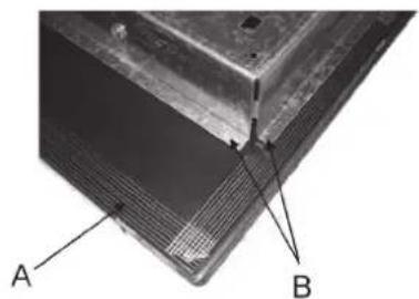
natural_image
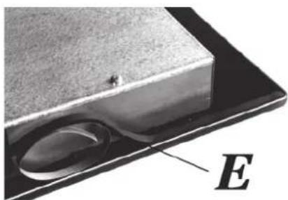
Close-up of a metallic panel with labeled points A and B, showing internal structure (no text or symbols beyond labels)The hob is fitted with a special gasket which prevents liquids from entering the cabinet. To apply this gasket correctly:
- Remove all moving parts from the hob.
- Cut the gasket into 4 pieces of the required length to fit the 4 edges of the glass.
- Turn the hob over and position the gasket correctly under the edge of the hob itself, so that the outer side of the gasket perfectly matches the outer perimeter edge of the glass. The ends of the strips should be close together without overlapping.
- Fix the gasket to the glass evenly and securely by pressing it with your fingers.
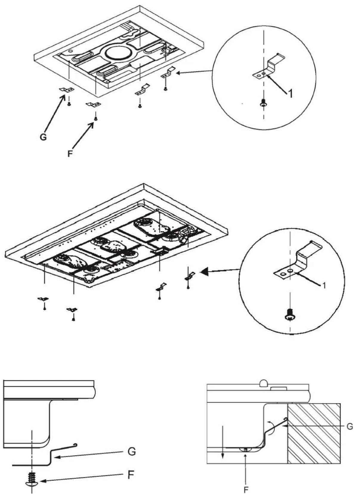
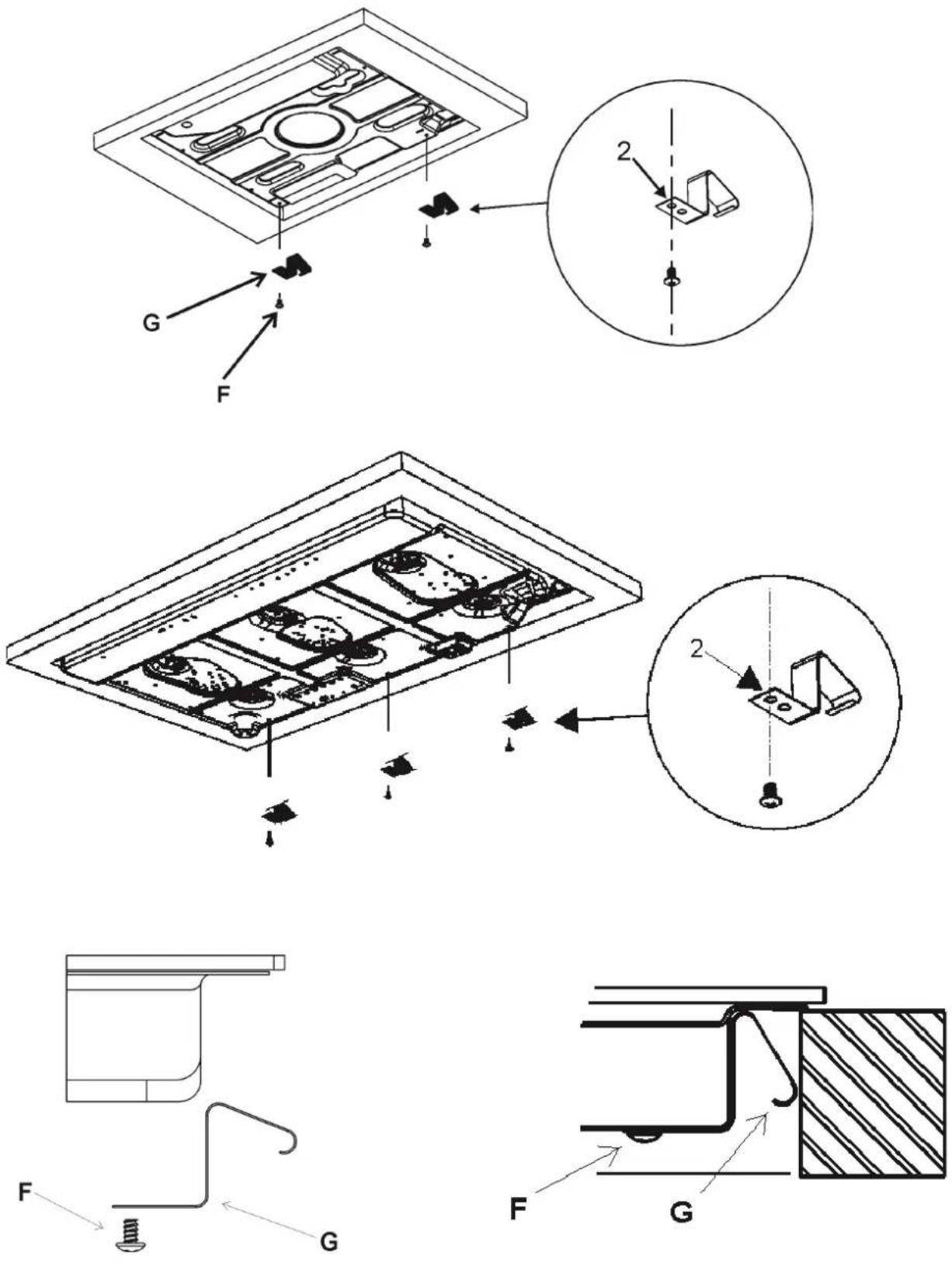
- Place the hooks in their respective positions, use hole no. 1 as a reference for the side position and hole no. 2 for the rear positions.
- Fix the hooks "G" using the screws "F" (f-In-
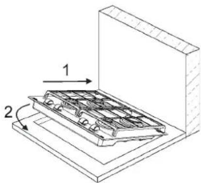
sert the hob into the hole in the kitchen unit using some force to overcome the resistance of the hooks).
- To avoid accidental contact with the overheated bottom of the hob during work, it is necessary to place a wooden insert, fixed with screws, at a distance of at least 70 mm from the top.
Caution: Do not allow the glass to rest directly on the worktop. It is the metal bottom frame that has to be in contact with the worktop.
IMPORTANT INSTALLATION REQUIREMENTS
- The back wall, surrounding surfaces and surfaces adjacent to the appliance must be able to withstand a temperature of 90°C.
- The adhesive used to glue the plastic laminate to the cabinet must withstand a temperature of at least 150°C. Otherwise, the laminate may crack or crack. Otherwise, the laminate could peel off.
- The appliance must be installed in accordance with current regulations.
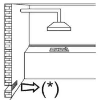
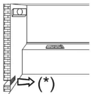
- This appliance is not connected to a device capable of evacuating combustion fumes. It must therefore be connected in accordance with the ventilation recommendations.
VENTILATION OF THE ROOM
The required air volume must not be less than 20 m ^3 . The air should flow naturally through permanent openings in the walls of the room in question. These openings must discharge the fumes to the outside and their cross-section must be at least 100 cm ^2 . The construction of the openings must ensure that they can never be blocked. Indirect ventilation by sucked-in air is also permitted.
WARNING: If the hob burners are not equipped with a thermocouple system, the air outlet must have a minimum clearance of 200cm^2 .
LOCATION AND AIRING
Gas cooking appliances must always exhaust their combustion fumes through hoods. These should be connected to ducts, chimneys or directly to the outside. If it is not possible to install a hood, an electric fan can be installed in a window or on a wall facing the outside. This must be activated at the same time as the appliance, provided that the specifications of the regulations in force are strictly observed.
GAS CONNECTION
Before connecting the appliance, check that the values given on the data label attached to the bottom of the hob correspond to those of the gas and electricity networks in the home.
A label on the appliance indicates the regulation conditions: type of gas and working pressure. The gas connection must comply with the relevant standards and regulations in force.
When the gas is supplied through pipes, the appliance must be connected to the gas supply network:
- With a rigid steel pipe. The connections of this pipe must be made with threaded fittings in compliance with the standards.
- With copper pipe. The joints of this pipe must consist of joints with mechanical seals.
- With seamless flexible stainless steel pipe. The length of this pipe must be a maximum of 2 metres and the joints must comply with the standards.
- When the gas is supplied by a cylinder, the appliance must be supplied by a pressure regulator in accordance with the regulations in force and must be connected with a copper pipe. The joints of this pipe must be formed by joints with mechanical seals.
- With a seamless stainless steel flexible pipe. The length of this pipe must be a maximum of 2 metres and the joints must comply with the standards. It is advisable to apply the special adapter to the flexible pipe. It can be easily purchased in shops and facilitates the connection to the hose nipple of the cylinder
pressure regulator.
- With rubber hose according to standards. The diameter of this hose must be 8 mm and its length must not be less than 400 mm and not more than 1500 mm. It must be firmly fixed to the hose nozzle by means of the safety clamp specified by the standards.
WARNINGS
Please note that the gas inlet union of the appliance is of the 1/2" conical male type in accordance with EN 10226 standards. The appliance complies with the provisions of the sub-regulations of the European Directives (EU) 2016/426.
When installing the stainless steel pipe and rubber hose, it must be ensured that the pipe can never touch moving parts of the built-in furniture (e.g. drawers). Furthermore, it must not pass through compartments that can be used for storage.
When using a rubber hose, it is essential to comply with the following instructions:
- No part of the pipe must be able to touch parts whose temperature exceeds 90 °C.
- The pipe must not be pulled, twisted, kinked or bent.
- It must not come into contact with sharp corners or edges.
- It must be easy to inspect the entire length of the hose for wear and tear.
- The hose must be replaced on the date indicated on the hose.
ELECTRICAL CONNECTIONS
IMPORTANT: the appliance must be installed in accordance with the manufacturer's instructions. The manufacturer accepts no liability for personal injury or material damage caused by incorrect installation.
The electrical connections of the appliance must be carried out in compliance with the regulations and standards in force.
Before connecting the appliance, check that the voltage matches the value indicated on the rating plate and that the cable cross-section of the electrical installation can withstand the load, which is also indicated on the rating plate.
The electrical capacity of the mains and power sockets is adjusted to the maximum power of the appliance (see the data label applied to the underside of the hob). The socket outlet or installation has an effective earth connection in accordance with the regulations and standards in force. The manufacturer declines all liability in the event of non-compliance with these provisions.
When the appliance is connected to the mains:
- fit the cable with a standard "C" plug suitable for the load indicated on the data label. Lay the cables according to figure A, taking care to observe the following correspondences:
Letter L (line) = brown cable Letter N (neutral) = blue cable Letter C = green cable - yellow
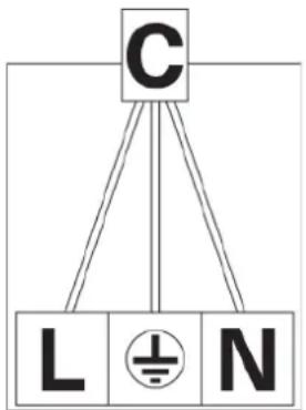
- The power cable must be laid in such a way
that no part of it can reach a temperature of 90^ C.
- Never use reducers, adapters or shunts for the connection, as they could create false contacts and cause dangerous overheating.
- The socket must be accessible after installation.
When the appliance is connected directly to the mains:
• Install an omnipolar circuit breaker between the appliance and the mains. This circuit breaker must be sized in accordance with the installation standards in force.
- Remember that the earth wire must not be interrupted by the circuit breaker.
- For optimum safety, the electrical connection may also be protected by a highly sensitive differential circuit breaker.
It is strongly recommended that the yellow-green earth wire be fixed to an effective earthing system.
Before carrying out any work on the electrical part of the appliance, it is absolutely necessary to disconnect it from the mains. Always disconnect the appliance from the mains before making any adjustments. All gaskets must be replaced by the technician at the end of any adjustment or adjustment. Our burners do not require primary air adjustment.
If the installation requires modifications to the electrical system of the home or if the socket is incompatible with the appliance's plug, have the modifications or replacements carried out by a professionally qualified person. In particular, this person must also ensure that the cable cross-section of the socket is suitable for the power absorbed by the appliance.
ADJUSTING THE CONTROLS
Setting the reduced flow rate
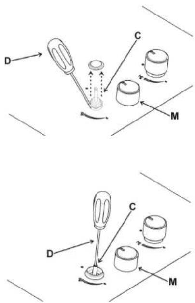
- Switch on the burner and turn the corresponding knob to the "Reduced flow rate" position.
- Remove the "M" knob from the tap, which is simply fitted on the rod. The minimum flow regulation by-pass can be on the side of the tap or on the inside of the shaft. In either case, the regulation can be accessed by inserting a small screwdriver (D) next to the tap or in the hole (C) inside the tap shaft. Turn the screw clockwise or counterclockwise until the burner flame has been properly regulated to the "Reduced flow" position. The flame must not be too low: the lowest flame must be continuous and stable.
- Reassemble the individual components.
Only burners operating with G20 should be subjected to the above adjustments. The screw must be completely locked when burners are operated with G30 or G31 (turn clockwise).
REPLACING PARTS
HOW TO REPLACE AN INJECTOR
Burners can be adapted to different types of gas if injectors suitable for the type of gas in question are fitted. To do this, first remove the upper part of the burner with a suitable tool. Then unscrew the injector and fit an injector corresponding to the type of gas used.
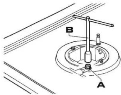
It is advisable to tighten the injector firmly in place. To access the injector, on high speed burners with DCC AFB, remove the injector cap "A".
Once the injectors have been replaced, the burners must be regulated as explained in section 9. The technician must readjust any seals on the regulation or pre-regulation devices.
The envelope with the injectors and labels may be included in the kit, or available from the customer's authorised Service Centre.
For greater convenience, the table of nominal tariffs also shows the calorific power of the burners, the diameter of the injectors and the working pressures of the different types of gas.
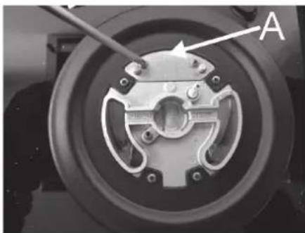
natural_image
Close-up of a mechanical component with labeled point A, showing internal parts and mounting holes (no text or symbols beyond label)HOW TO REPLACE BURNER PARTS
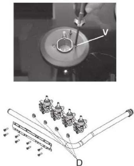
Always disconnect the appliance from the electricity and gas mains before carrying out any maintenance operation.
When it is necessary to replace parts of the hob, first remove the hob from the cabinet, remove the trivets, knobs and gas burner, unscrew the screws and remove the glass.
Then the burners, taps and electrical components can be replaced. It is advisable to change the gasket every time a tap is replaced to ensure a perfect seal.
If a tap becomes stiff when operated, it must be greased immediately by following the instructions below:
- disassemble the tap.
- Clean the cone and its housing with a cloth soaked in thinner.
- Lightly grease the cone.
- Put the cone back in place, operate it several times and then disassemble it again. Remove excess grease and check that the gas lines are not obstructed.
- Put all parts back in place, following the reverse order of disassembly.
- The tightness test must be carried out with a foaming liquid. The use of naked flames is prohibited.
MAINTENANCE MUST BE CARRIED OUT ONLY BY AUTHORISED PERSONS.
natural_image
Mechanical assembly diagram showing a valve inserted into a circular component with a close-up of internal components (no text or labels)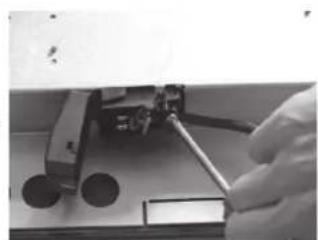
natural_image
Close-up of a hand using a tool to adjust or install a mechanical component (no visible text or symbols)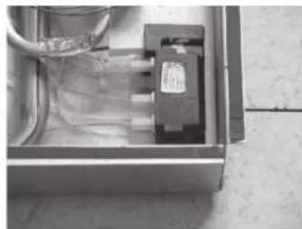
natural_image
Interior view of an open electrical enclosure with visible wiring and a small component (no text or symbols)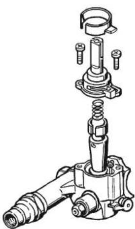
natural_image
Technical illustration of a mechanical assembly with exploded view (no text or labels)Type of cable: H05 RR-F
Single-phase power supply: Section 3 x 0.75 mm ^2
WARNING!
If the power cable is replaced, the installer must leave the earth cable longer than the phase conductors and comply with the recommendations.
In the event of a fault or cut cable, move away
from the cable and do not touch it. Also unplug the appliance and do not switch it on. Call the nearest authorised service centre to solve the problem.
In case of adaptation of the hob to another type of gas, operate as described in the instructions and replace the label on the bottom with the one supplied in the replacement bag.
TECHNICAL INFORMATION
| BURNERS GAS | PRESSURE (mbar) | THERMAL CAPACITY | ∅ NOZZLE 1/100mm | THERMAL CAPACITY (W) | |||||
| No. | NAME g/h l/h M | N MAX | EE gas burners | ||||||
| 1 ultra-fast | G30 - BUTANE | 28-30 | 291 | 381 | 100 H1 | 1800 | 4000 | 56,0 % | |
| G31 - PROPANE | 37 | 100 H1 | 1800 | 4000 | |||||
| G20 - NATURAL | 20 | 286 | 145 Z1 | 1800 | 4000 | ||||
| 2 fast | G30 - BUTANE | 28-30 | 204 | 267 | 83 | 900 | 2800 | 58,0 % | |
| G31 - PROPANE | 37 | 83 | 900 | 2800 | |||||
| G20 - NATURAL | 20 | 200 | 117 S | 900 | 2800 | ||||
| 3 | semi-fast reduced | G30 - BUTANE | 28-30 | 102 | 133 | 60 | 550 | 1400 | 60, |
| G31 - PROPANE | 37 | 60 | 550 | 1400 | |||||
| G20 - NATURAL | 20 | 100 | 88 Z | 550 | 1400 | ||||
| 4 semi-fast | G30 - BUTANE | 28-30 | 127 | 167 | 65 | 550 | 1750 | 63,0 % | |
| G31 - PROPANE | 37 | 65 | 550 | 1750 | |||||
| G20 - NATURAL | 20 | 125 | 97 Z | 550 | 1750 | ||||
| 5 auxiliary | G30 - BUTANE | 28-30 | 73 | 95 | 50 | 450 | 1000 | 0 % | |
| G31 - PROPANE | 37 | 50 | 450 | 1000 | |||||
| G20 - NATURAL | 20 | 71 | 72 X | 450 | 1000 | ||||
| CAT. = II2H3+ FREQUENCY: 50-60Hz VOLTAGE: 220-240V | NATURAL GAS G20 20mbar | BUTANE GAS G30 28-30mbar | PROPANE GAS G31 37mbar | EE gas burners |
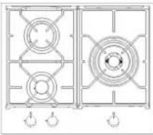 | 7,8 kW 567 | g/h 557 g/h 57,8 % | ||
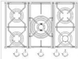 | 10,95 kW 796 | g/h 782 g/h 59,5 % | ||
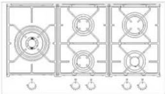 | 10,95 kW 796 | g/h 782 g/h 59,35 %. |
PRODUCT WARRANTY
INOXPAN S.L., thanks you for choosing and placing your trust in a product of our brand Pando, which is distinguished by its Quality, Design and Innovation, being faithful to its origins and commitments.
PANDO WARRANTY CONDITIONS
This appliance is guaranteed for 3 years from the date of purchase and covers it against any manufacturing defect that may affect its proper operation. For the validity of the warranty to be valid, it is essential to present the invoice or purchase receipt to the Pando Authorised Service technician.
During this period, the Company undertakes to replace or repair free of charge any defective part due to a defect or manufacturing defect in the appliance, until it is in proper working order, as well as the necessary labour and expenses incurred as a result of such repair or replacement.
EXCLUSIONS FROM THE PANDO WARRANTY:
It will not be covered by the product warranty and could be cause for cancellation of this, and in these cases the user will be responsible for the costs of materials, labour and travel of the technical service, in the following cases:
- If the installation of the product has not been carried out by Authorised Professional Specialists, Lamp fitters or Electricians, or by Pando Technical Service personnel, who meet the requirements of safety standards and gas and electricity regulations.
- Breakdowns or damage caused by transport or transfer, manipulation of the device by unauthorised personnel not authorised by this company or the Pando brand.
- Faults or malfunctions caused by failure to observe or follow the safety, operating and maintenance instructions in the product manual.
- Breakdowns or problems caused by not having the required free spaces in the furniture, as indicated in the installation manual, for adequate ventilation of the product.
• The installation does not have the mandatory and standardised safety elements for power disconnection. - The technician does not have easy access to the product, because there are elements that prevent easy and safe access. The means required for the authorised Pando technician to access the device are the responsibility of the user.
- The product does not have the appropriate product label or nameplate for the type of gas connected.
- The installation of the product, nor the modification of gas type (change of injectors).
- Carrying out inspections or commissioning, cleaning or maintenance of the product.
- When the product is intended for commercial or non-domestic use, for which it is not intended.
- Aesthetic components of wear and tear, all burner accessories, grills, controls, nozzles.
- Rust, burns, stains or discolouration of the product and accessories caused by improper maintenance or use, or by improper application or unprotected exposure to corrosive elements such as cleaning agents not recommended by the manufacturer and unsuitable cleaning agents.
- Blows, deformations, dents, scratches, scuffs, breakages on the body, glass or accessory elements of the product.
- Presence of foreign bodies foreign to the device, inside or outside the product.
- Breakdowns or damage caused by variations in the electricity supply or fortuitous and natural causes of atmospheric or geological origin such as storms, lightning, earthquakes, floods, etc.
- Appliances from resale, second hand, trade-in or exhibitions that are more than three years old from the date of manufacture.
INOXPAN, S.L., is expressly excluded from any liability for any direct or indirect damage to persons or materials caused by improper handling of the device.
Contact details Offi cial Authorised Pando Technical Service:
| ESPAÑA, PORTUGAL Y ANDORRA OTROS | PAÍSES | ||
| www.pando.es/asistencia-tecnica/ | www.pando.es/en/after-sales-services/ | ||
Pol. Ind. El Cros
SERVICIO
POSVENTA

Environmental Management System Certification
UNE-EN ISO 14001:2015
ES20/208675


- Pando integralcooking
- The Global Kitchen Partner
- TRATAMIENTO DEL RESIDUO
- USO DE LA PLACA
- QUEMADORES
- CÓMO SUSTITUIR PIEZAS DE LOS QUEMADORES
- POUPANÇA DE ENER- GIA E CUIDADOS COM A PANELA
- COMO SUBSTITUIR AS PEÇAS DO QUEIMADOR
- TRAITEMENT DES DÉCHETS
- AVERTISSEMENTS DE SÉCURITÉ
- ÉCONOMIE D'ÉNERGIE ET MAINTENANCE DES POÊLES
- REEMPLACEMENT DES PIÈCES
- COMMENT REMPLACER UN INJECTEUR
- COMMENT REMPLACER LES PIÈCES DU BRÛLEUR
- ENVIRONMENTAL PROTECTION
- WASTE TREATMENT
- INDEX
- SAFETY WARNINGS
- please contact Customer Service.
- Risk of explosion!
- IF YOU FEEL A SMELL OF GAS OR IF THERE IS A DAMAGE TO THE GAS SYSTEM:
- Always place liquid gas cylinders in an upright position.
- Risk of poisoning!
- To install an additional ventilation device, contact qualified personnel.
- Risk of fire!
- Risk of burns!
- Risk of electric shock!
- Risk of injury!
- If the appliance is faulty:
- Risk of suffocation!
- AVOID MATERIAL DAMAGE
- DESCRIPTION OF THE COOKING PANEL
- RECOMMENDATIONS FOR USE
- USE OF THE DISPLAY
- BURNERS
- • Automatic electric ignition
- - Ignition of burners fitted with safety thermocouple (flame failure)
- HOW TO USE THE BURNERS
- CLEANING
- SURFACE
- ENERGY SAVING AND PAN CARE
- BEFORE INSTALLATION
- TECHNICAL INFORMATION FOR THE INSTALLER
- PLATE POSITIONING
- DIMENSIONS OF THE PLATES
- FITTING DIMENSIONS
- INSTALLATION
- REAR GRAPHS
- CORRECT INSTALLATION OF THE PANEL
- IMPORTANT INSTALLATION REQUIREMENTS
- VENTILATION OF THE ROOM
- LOCATION AND AIRING
- GAS CONNECTION
- WARNINGS
- ELECTRICAL CONNECTIONS
- ADJUSTING THE CONTROLS
- REPLACING PARTS
- HOW TO REPLACE AN INJECTOR
- HOW TO REPLACE BURNER PARTS
- WARNING!
- PRODUCT WARRANTY
- PANDO WARRANTY CONDITIONS
- EXCLUSIONS FROM THE PANDO WARRANTY:
Brand : Pando
Model : PGA-4371
Category : Cooker