HE400 - Humidifier HONEYWELL - Free user manual and instructions
Find the device manual for free HE400 HONEYWELL in PDF.

User questions about HE400 HONEYWELL
0 question about this device. Answer the ones you know or ask your own.
Ask a new question about this device
Download the instructions for your Humidifier in PDF format for free! Find your manual HE400 - HONEYWELL and take your electronic device back in hand. On this page are published all the documents necessary for the use of your device. HE400 by HONEYWELL.
USER MANUAL HE400 HONEYWELL
HE400 Humidification System
INSTALLATION GUIDE

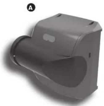
INCLUDED IN THIS HUMIDIFIER BOX
natural_image
3D rendered image of a gray mechanical component with a curved cutaway view (no text or symbols)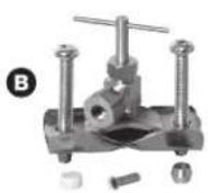

E

G
Tools needed to install humidifier
→ Wire cutter/stripper
▶ Tin snips or sheet metal cutter
8 hex nut driver
Standard screwdriver
18-gauge wire (up to 5 conductor)
Other Requirements
If floor drain is not available, refer to Appendix C for additional plumbing parts consideration.
If installed in or above a finished space, Resideo recommends installing a drip pan with water sensor shut-off.
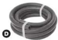
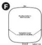
A Humidifier Bypass
B Saddle valve
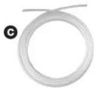
© Water supply line
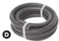
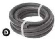
D Drain hose (10 feet)
E Literature
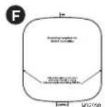
F Mounting template
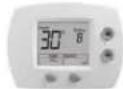
G HumidiPRO Digital humidity control
Hardware (not pictured)
Transformer
2 foot by-pass duct
Cross Reference Table
| Humidifier Honeywell Home Aprilaire® | GeneralAire® | ||
| HE400 | HE200 | HE250 | HE265 |
GETTING STARTED
Safety Definitions and Precautions....2
What to Expect From Your Humidifier....3
Important Installation Requirements ....4
MOUNTING
Choosing a Mounting Method 5
STEP ONE: Select the Mounting Location ..... 5
STEP TWO: Install Mounting
Template to the Duct....6
STEP THREE: Configure Humidifier....6
STEP FOUR: Mounting....7
STEP FIVE: Bypass Duct Installation....8
PLUMBING
Water Supply and Drain Connections....9
STEP ONE: Connect the Water Supply ..... 9
STEP TWO: Tap into a Water Line ..... 9
STEP THREE: Connect to the Water Drain ....10
WIRING
Before Wiring Humidifier....11
STEP ONE: Remove the Humidifier Cover .....11
STEP TWO: Install the Transformer .....11
STEP THREE: Wiring Humidifier .....11
Installing the Humidistat....12
Remote Installation....12
Duct Installation....12-13
Wiring the Humidistat....13
Wiring Configuration....14
Outdoor Sensor....15-16
OPERATION AND SERVICE
Startup and Checkout....20
Routine Maintenance....21
Troubleshooting 21
APPENDICES
A: Specifications 22
B: Advanced Draining 23
C: Parts List 24

NEED HELP? For assistance with this product please visit http://honeywellhome.com or call Customer Care toll-free at 1-800-468-1502.
Read and save these instructions.
Safety Definitions and Precautions
Safety Definitions
These safety terms identify information you must read prior to installing or operating the humidifier.

CAUTION: Indicates a hazardous situation which, if not avoided, could cause bodily injury or property damage.

WARNING: Indicates a hazardous situation which, if not avoided, could result in death or serious injury.
Safety Precautions
Make sure you read and understand the following safety hazards before installing, using, or working with the humidifier:

CAUTION: Voltage Hazard.
Can cause electrical shock or equipment damage.
Disconnect HVAC equipment and any electrical outlet being used for the humidifier installation.

WARNING: Electrocution and Water Hazard.
Can cause death, blindness, and water damage to the home and HVAC Equipment.

CAUTION: Condensation, Fire, and Freezing Water Hazard.
Can cause failure of fan or limit control or result in water damage to home.
What to Expect From Your Humidifier
The installer should review these points with the homeowner and answer any questions they have before leaving the job site.
- Achieving Humidity Setpoint. It may take up to a week of continuous operation to achieve the humidity setpoint, especially if the home is dry when the humidifier is installed. This also depends on such factors as weather, size of home, furnishings in the home, and insulation.
- Ideal Humidity. Home building industry experts cite 35% relative humidity as ideal for comfort and safeguarding the home during the typical dry season. Homeowners can adjust to their own comfort or until there is condensation on the windows. Lower the setpoint if condensation appears.
- Unit Not Humidifying. If the humidifier is not running but the humidity is below the setpoint, the humidity control may have a frost protection setting to prevent window condensation from appearing.
- Home Ventilation. Excessive ventilation sends moist air outside and replaces it with dry air. This can make it hard to maintain the humidity setpoint. If installing a ventilator, use a solution that retains moisture. An Energy Recovery Ventilator (ERV) is recommended.
- Cleaning Requirements. The humidifier pad should be changed at least once a year. The water trays of the humidifier should be cleaned at that time. See Operation and Service section for details.
- Energy Consumption. It is important to explain that with any humidification solution there is a cost associated with converting water to humidity. The humidifier utilizes the air heat and air flow in your ducting to make this conversion, which has gas and/or electric costs that depend on your HVAC system type and setup.
Important Installation Requirements
Failure to comply with these requirements will result in voided warranty, improper installation, and service callbacks.
Personal Safety
- Wear safety glasses while installing the humidifier.
- Do not cut into any air conditioning or electrical line.
- Follow professional safety standards and all local regulations for plumbing, electrical, and mechanical considerations.
Mounting Location
- Mount the humidifier in a level position to avoid water damage and ensure maximum output.
- Location must have access to a water line, drain, and power.
- Do not install the humidifier where the ambient temperature is lower than 34^ (1.1°C) or higher than 90^ (40°C).
- Mounting area must be strong enough to support humidifier weight (up to 10 lbs).
- Do not mount directly to ductboard.
- If used near a pool or spa, make sure the humidifier can not fall into the water or be splashed.
- Ensure that the top and bottom covers of the humidifier can be removed and that the pad is accessible from the chosen location.
Water Supply and Drainage
- Consult local plumbing codes for drain size, material, and maximum temperature allowed.
If Replacing an Old Bypass Humidifier
The humidifier is not identical in size and shape to other bypass humidifiers. Before performing a retrofit installation, you might need to:
- Dry-fit the humidifier to the existing ducting, plumbing, and wiring before fastening it to the duct to ensure that the existing connections will reach the humidifier.
- If the duct opening of the old humidifier is not the right size for the humidifier, choose a new location or cover the old opening with a piece of sheet metal and cut a new opening specifically for the humidifier using the template provided.
Cross Reference Table
| Humidifier Honeywell Home Aprilaire ^8 | GeneralAire ^6 | ||
| HE400 HE200 HE250 HE265 | |||
Choosing a Mounting Method
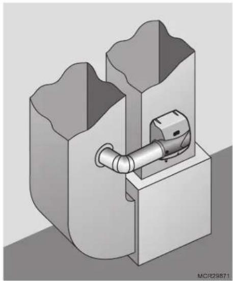
Bypass humidifiers use the pressure difference between the supply and return to move duct air through the humidifier. Access to both the supply and return are required. The bypass humidifier can be positioned on either the supply or return duct.
natural_image
3D technical illustration of a pipe fitting inside a mechanical housing (no text or symbols)Before beginning Mounting:
☐ I have confirmed local codes for proper plumbing practices.
☐ I have chosen an installation location that meets the requirements on page 4.
STEP ONE: Select the Mounting Location
text_image
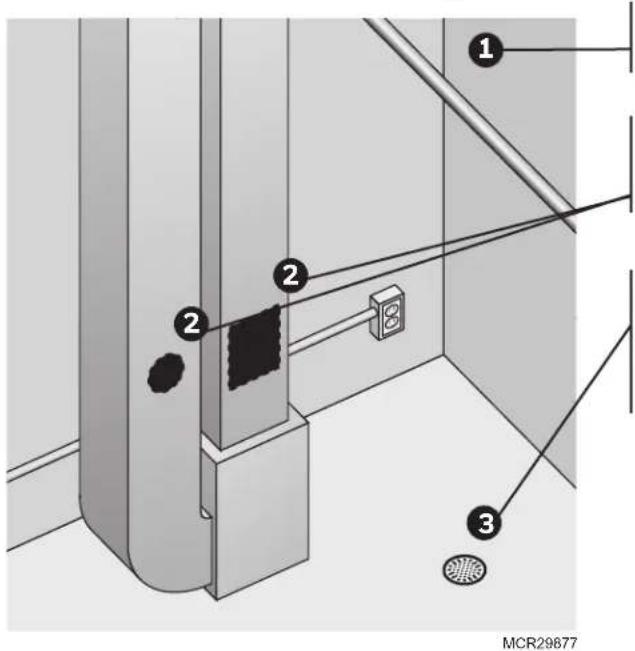
1 2 2 3 MCR29877Choose a location that has access to a water supply pipe. Cold or hot water can be used.
Select a vertical or horizontal surface on the HVAC duct work, with adequate space clearances, where the humidifier can be mounted.
Ensure the location is near a drain. Consult local plumbing codes for proper drainage. If no main floor drain is available, see "Appendix B: Advanced Draining."
Location must also have access to 120 VAC power to the included transformer.
STEP TWO: Install Mounting Template to the Duct
text_image
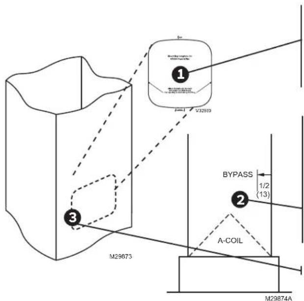
M29673 M29874A 1 2 3 BYPASS 1/2 (13) A-COILPosition the template on the duct.
- Make sure the template is level and in the desired position on the duct. Peel adhesive backing and press template firmly into place in desired mounting location.
Ensure proper clearances from the air-conditioning coil inside the duct.
NOTE: The HE400 humidifier extends into the duct 1/2 inches.
- For best performance, maintain at least 24 inches downstream of open air space inside the duct.
Cut the sheet metal, following the template outline.
Bypass Model Installation
STEP THREE: Configure Humidifier
text_image
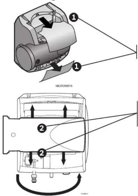
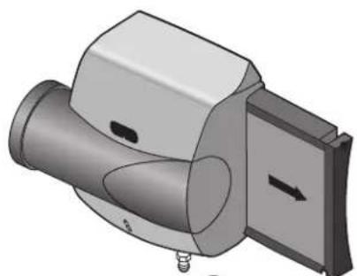
MCR29875Configure the humidifier bypass outlet to the side that best fits the application.
If the bypass needs to be on the other side, remove the top and bottom covers.
Pull the bypass clamps apart from center to remove the bypass; snap it back into place with the outlet on the desired side.
text_image
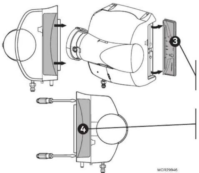
Technical diagram of a mechanical device with labeled parts and directional arrows indicating assembly or assembly.STEP FOUR: Mounting

text_image
① ② MCR29870Ensure that the pad is accessible. The handle of the pad holder and side panel of the humidifier can be switched so the pad holder can be removed (opposite side of the bypass duct opening).
To remove the handle for the pad holder, slide it toward the back of the humidifier, then pull it away from the humidifier.
To remove the opposite side panel, place a screwdriver into the two slots on the back of the humidifier, and pop the panel off.
Snap the pad holder handle and side panel back into place in the desired configuration.
Secure the support hooks on Bypass models to the bottom lip of the hole.
Push the top of the humidifier back against the duct.
Verify the humidifier is level and fasten the humidifier to the duct using two self-drilling sheet metal screws provided.
Bypass Model Installation
STEP FIVE: Bypass Duct Installation
text_image
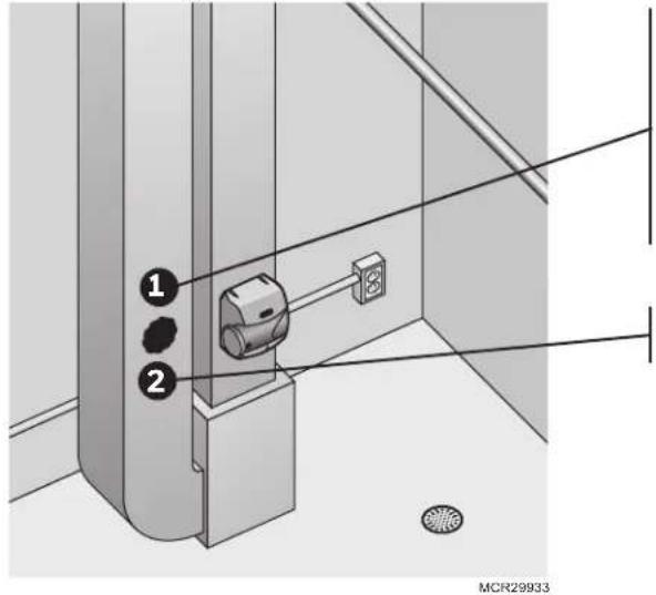
1 2 MCR29933On the duct opposite the humidifier Bypass install, cut a 6-in. diameter duct hole.
- If the humidifier is on the supply duct, the 6-in. diameter hole should be on the return.
- If the humidifier is on the return duct, the 6-in. diameter hole should be on the supply.
Secure a 6-in. round duct starter collar into the 6-in. duct hole.
text_image
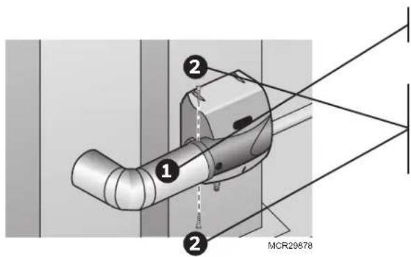
1 2 MCR29878Use rigid or aluminized flexible 6-in. duct to connect the starter collar to the humidifier bypass port.
Secure the duct to the humidifier port with self-drilling sheet metal screws using the pre-drilled holes on the bypass port. For added seal, wrap sheet metal tape around the duct to port connection point.
Bypass mounting is complete. Go to page 12.
Before proceeding to the next step:
☐ I secured the humidifier to the duct as instructed.
Water Supply and Drain Connections
STEP ONE: Connect the Water Supply
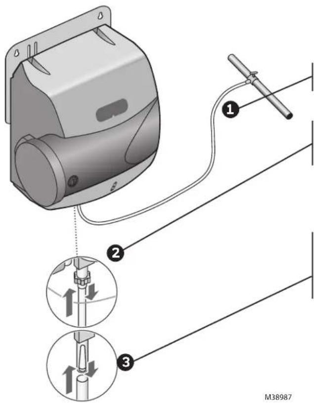
text_image
Technical diagram showing a device with three labeled parts: connection to cable, assembly with arrows indicating motion, and a separate view of the cable being inserted.Use hot or cold water.
Cut the water line so it reaches from the humidifier to the main water supply tap.
Insert the water line into the gray quick connect fitting. Insert it fully, and apply modest pull pressure to ensure a tight fit.
Note: The quick connect fitting can be removed if you prefer to use a standard 1/4-in. brass compression nut plumbing connection. Do not remove the filter if you select this option.
STEP TWO: Tap into a Water Line
text_image
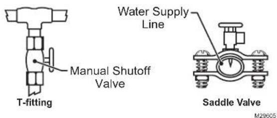
T-fitting Manual Shutoff Valve Water Supply Line Saddle Valve M29605- Consult local codes for proper plumbing.
- Use the saddle valve provided or a T-fitting and manual shutoff valve to tap into the water line.
- Refer to the literature included with the valve you chose and the local plumbing codes. Use proper technique for the valve.
- Connect the other end of the humidifier water line to the water valve.
STEP THREE: Connect to the Water Drain
text_image
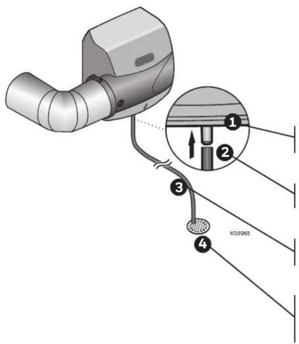
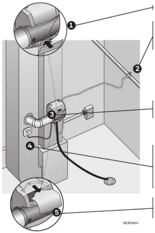
M38968- Consult and follow local plumbing codes for drain pipe size and flow requirement.
- The ideal installation is directly to the main floor drain using the rubber hose provided.
- If direct floor drain access is not available, see "Appendix C: Advanced Draining."
Connect the 1/2-in. drain hose provided to the drain fitting on the bottom of the humidifier.
Use the hose clamp provided to secure the drain hose to the fitting.
Route the drain hose to the floor drain. The hose must have a continuous downward slope.
Direct the hose outlet into the floor drain. Secure the hose to reduce the risk of water pooling or splashing as it drains from the humidifier.
Before proceeding to Wiring:
☐ I have connected the water supply line to the humidifier and the main water tap.
☐ I have installed the drain connection.
☐ I have checked all plumbing connections for leaks.
Before Wiring the Humidifier

CAUTION: Voltage Hazard.
Be sure the humidifier is not plugged in before beginning wiring.
Before wiring the humidifier:
☐ I understand and will comply with applicable local wiring codes and regulations.
What humidifier model do I have?
The model number can be found on the bottom of the humidifier.
NOTE: This file is for the HE400 humidifier.
STEP ONE: Remove the Humidifier Cover
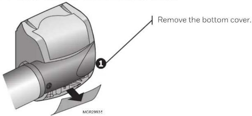
text_image
Remove the bottom cover. MCR28835STEP TWO: Install the Transformer
Install transformer on the outside of a grounded metal junction box using only a 7/8 in. (22 mm) knockout hole. Place mounting tabs into the knockout hole and firmly tighten the locking screw. Field wiring connections and grounding means for the transformer and enclosure shall be in accordance with the National Electrical Code (NEC) and the Canadian Electrical Code (CEC). Connect wires to the 120V side of the transformer.
If included H6062 humidistat is used for humidity control, transformer must provide constant power to the R and C terminals on the H6062.
STEP THREE: Wiring the Humidifier
Use a wiring diagram from the following pages that matches your equipment.
When wiring is complete, run the wires coming out of the humidifier into the wiring clip on the bottom of the humidifier.
Installing the Humidistat
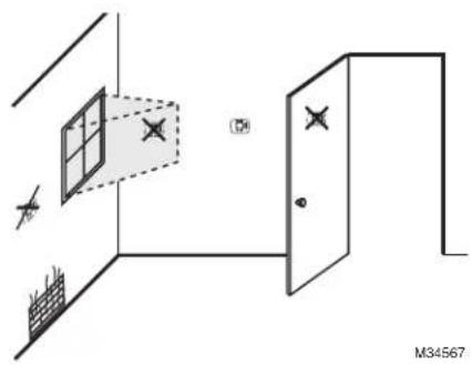
Remote Mount Installation
Choose a location in the living area.
NOTE: Select a location clear of drafts or excessive humidity. Avoid mounting near doors or windows, or in bathrooms or kitchens.
natural_image
Diagram showing a room with a window, door, and wall, marked with X marks (no text or symbols)OR
Duct-Mount Installation (recommended)
- Choose a location on the RETURN duct.
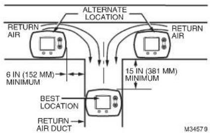
flowchart
graph TD
    A["RETURN AIR"] --> B["ALTERNATE LOCATION"]
    B --> C["6 IN (152 MM) MINIMUM"]
    B --> D["15 IN (381 MM) MINIMUM"]
    C --> E["BEST LOCATION"]
    D --> F["RETURN AIR DUCT"]
    E --> G["M34579"]
    F --> G
Warning: Product must be mounted on the RETURN side of the duct for proper RH% sensing.
- Separate wallplate from humidistat.
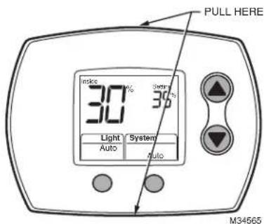
text_image
PULL HERE 30% 30% Light System Auto Auto M34565Caution: Electrical Hazard
Can cause electrical shock or equipment damage. Disconnect power before beginning installation.
- Mark the duct-tube hole.
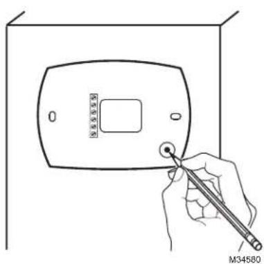
text_image
M34580Hold the wallplate up to the desired location on the duct and make a mark inside the duct tube hole.
- Drill the duct-tube hole.
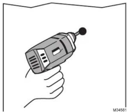
natural_image
Illustration of a hand holding a handheld electric drill (no text or symbols)Find your mark and drill a 1/2 in. hole in the duct. This is where the duct tube will be inserted to capture air.
Installing the Humidistat
Duct-Mount Installation (continued)
- Insert the duct tube.
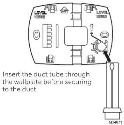
text_image
Insert the duct tube through the wallplate before securing to the duct.- Secure the wallplate.
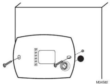
natural_image
Technical line drawing of a vehicle front view with sensors and a circular component (no text or symbols)Secure the wallplate to the duct with sheet metal screws (provided).
- Run wires through the back plate.
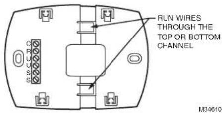
text_image
RUN WIRES THROUGH THE TOP OR BOTTOM CHANNEL M34610Run wires through the top or bottom channel on the back plate when duct-mounted. If installing like a thermostat on a wall, run the wires through the back.
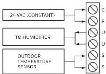
Wiring the Humidistat
This humidity control is wired the same way a manual humidistat (H8908) is wired. The only difference is that you also wire in power (24 VAC) and an outdoor sensor.
TERMINAL DESIGNATION
C 24 VAC POWER FROM EQUIPMENT
R 24 VAC POWER FROM EQUIPMENT
U HUMIDIFIER*
U HUMIDIFIER
S OUTDOOR SENSOR
S OUTDOOR SENSOR
flowchart
graph LR
    A["24 VAC (CONSTANT)"] --> B["C"]
    A --> C["R"]
    A --> D["U"]
    A --> E["S"]
    F["TO HUMIDIFIER"] --> G["U"]
    F --> H["S"]
    I["OUTDOOR TEMPERATURE SENSOR"] --> J["S"]
NOTES: C AND R MUST BE CONSTANT 24VAC! RECOMMENDED TO WIRE TO FURNACE/AIR HANDLERCONTROL BOARD.
DO NOT WIRE C AND R TO HUMIDIFIER TRANSFORMER IF THAT TRANSFORMER IS ONLY POWERED WHEN FAN IS RUNNING.
* 24 VOLTS NEEDS TO BE WIRED IN SERIES WITH THE HUMIDIFIER ON U TERMINALS. SEE WIRING DIAGRAMS. M34
M34865A
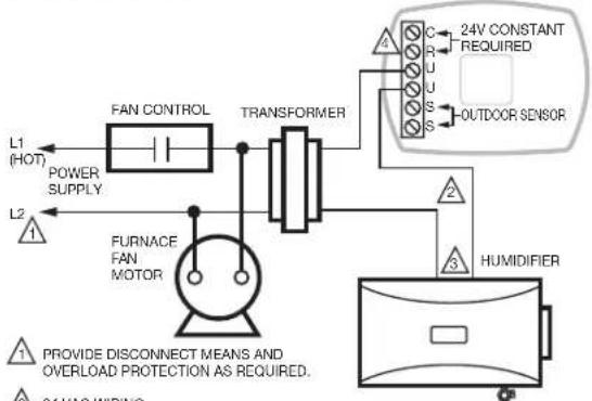
Wiring Configuration
Wiring H6062 HumidiPRO to HE400 with Fan Interlock.
flowchart
graph TD
    A["L1 (HOT)"] --> B["FAN CONTROL"]
    C["L2"] --> D["FURNACE FAN MOTOR"]
    B --> E["TRANSFORMER"]
    D --> E
    E --> F["24V CONSTANT REQUIRED"]
    E --> G["OUTDOOR SENSOR"]
    H["HUMIDIFIER"] --> I["3"]
    I --> J["2"]
    J --> K["2"]
    K --> L["2"]
    L --> M["2"]
    M --> N["2"]
    N --> O["2"]
    O --> P["2"]
    P --> Q["2"]
    Q --> R["2"]
    R --> S["2"]
    S --> T["2"]
    T --> U["2"]
    U --> V["2"]
    V --> W["2"]
    W --> X["2"]
    X --> Y["2"]
    Y --> Z["2"]
24 VAC WIRING.
3 24 VOLT R AND C FROM TRANSFORMER SHOULD ALSO BE WIRED TO R AND C ON THE DIGITAL HUMIDITY CONTROL IF USED.
4 THE R AND C ON H6062 MUST BE POWERED BY A DIFFERENT TRANSFORMER IF THE TRANSFORMER POWERING THE HUMIDIFIER IS WIRED THIS WAY. M34570C
Wiring HumidiPRO with 2-speed fan motor.

flowchart
graph TD
    L1["POWER SUPPLY"] --> FAN_CONTROL
    L2["Power Supply"] --> FAN_CONTROL
    FAN_CONTROL --> TRANSFORMER
    TRANSFORMER --> C["R"]
    TRANSFORMER --> U["U"]
    TRANSFORMER --> S["S"]
    TRANSFORMER --> OUTDOOR["OUTDOOR SENSOR"]
    DPST_SWITCHING_RELAY --> H["Pump"]
    DPST_SWITCHING_RELAY --> L["L"]
    DPST_SWITCHING_RELAY --> C["C"]
    H --> 2_SPEED["FAN MOTOR"]
    L --> 2_SPEED["FAN MOTOR"]
    2_SPEED["FAN MOTOR"] --> H
    2_SPEED["FAN MOTOR"] --> C
    style FAN_CONTROL fill:#f9f,stroke:#333
    style TRANSFORMER fill:#ccf,stroke:#333
    style H fill:#fff,stroke:#333
    style C fill:#fff,stroke:#333
    style H fill:#fff,stroke:#333
    style C fill:#fff,stroke:#333
    style OUTDOOR fill:#fff,stroke:#333
    style HUMIDIFIER fill:#fff,stroke:#333
1 PROVIDE DISCONNECT MEANS AND OVERLOAD PROTECTION AS REQUIRED.
2 24 VAC WIRING.
THE R AND C ON H6062 MUST BE POWERED BY A DIFFERENT TRANSFORMER IF THE TRANSFORMER POWERING THE HUMIDIFIER IS WIRED THIS WAY. M34571B
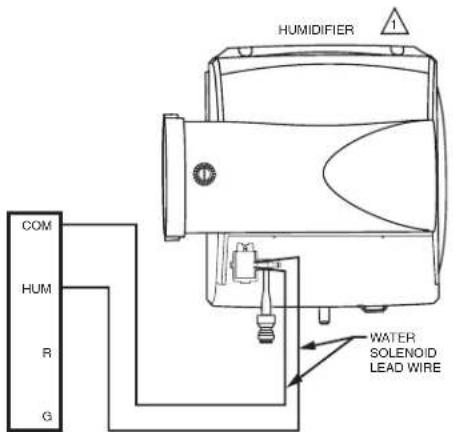
Wiring TrueEASE to equipment with powered terminals.
text_image
HUMIDIFIER COM HUM R G WATER SOLENOID LEAD WIRE1 WIRING DIAGRAM ASSUMES THE USE OF EQUIPMENT-SPECIFIC COMMUNICATING THERMOSTAT CONTROLLING THE HUMIDIFIER. M35039
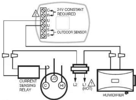
Wiring HumidiPRO with current-sensing relay.
flowchart
graph TD
    A["24V CONSTANT REQUIRED"] --> B["C"]
    A --> C["R"]
    A --> D["U"]
    A --> E["S"]
    A --> F["S"]
    B --> G["OUTDCOR SENSOR"]
    C --> H["Current Sensing Relay"]
    D --> I["LO"]
    E --> J["HI"]
    F --> K["L2"]
    K --> L["L1 (HOT)"]
    L --> M["HUMIDIFIER"]
    M --> N["Ground"]
1 PROVIDE DISCONNECT MEANS AND OVERLOAD PROTECTION AS REQUIRED.
2 R AND C FROM H6082 HUMIDITY CONTROL SHOULD WIRE DIRECT TO R AND C OF TRANSFORMER. M34572C
Wiring HumidiPRO in line with air proving device.
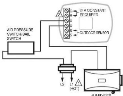
flowchart
graph TD
    A["AIR PRESSURE SWITCH/SAIL SWITCH"] --> B["24V CONSTANT REQUIRED"]
    B --> C["OUTDOOR SENSOR"]
    C --> D["HUMIDIFIER"]
    D --> E["L1 (HOT)"]
    E --> F["L2"]
    F --> G["Ground"]
1 PROVIDE DISCONNECT MEANS AND OVERLOAD PROTECTION AS REQUIRED.
2 R AND C FROM H6062 HUMIDITY CONTROL SHOULD WIRE DIRECT TO R AND C OF TRANSFORMER. M345758
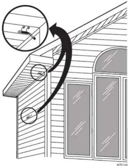
Mounting the Outdoor Sensor
(Not required if window protection isn't needed)
Location
Mount the sensor where:
- it cannot be tampered with.
• there is good air circulation.
- surface is flat.
- wire distance between sensor and humidistat is less than 200 feet.
- it can measure true outdoor ambient temperature.
Do NOT mount the sensor:
- in direct sunlight.
• where snow, ice or debris can cover it.
- where hot or cold air blows on the sensor. (For example, a discharge line from an outdoor compressor unit, vent or fan can cause inaccurate temperature readings.)
Steps to mount the sensor
-
Remove the sensor from the mounting clip.
-
Mark the area on the location selected for mounting the sensor mounting clip.
-
Mount the clip. Image on right shows typical locations for outdoor sensor.
text_image
Diagram illustrating window frame installation with magnified detail and directional arrow, showing structural components and measurement indicators.Wiring the Outdoor Sensor
CAUTION: Electrical Interference (Noise) Hazard. Can cause erratic system operation.
Keep wiring at least one foot away from large inductive loads such as motors, line starters, lighting ballasts and large power distribution panels.
Use shielded cable to reduce interference when rerouting is not possible.
Be sure wires have a cable separate from the thermostat cable.
Do not route temperature sensor wiring with building power wiring, next to control contactors or near light dimming circuits, electric motors or welding equipment.
Avoid poor wiring connections.
Avoid intermittent or missing building earth ground.
CAUTION: Electrical Shock Hazard. Can cause electrical shock or equipment damage.
Disconnect power supply before connecting wiring.
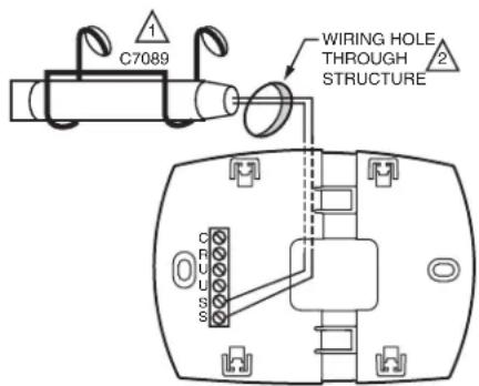
Wiring must comply with applicable codes, ordinances and regulations:
-
Wire the C7089 Outdoor Sensor to the S terminals on the humidity control. If leadwire provided with C7089 is not long enough (60 in.), run a cable to a hole at C7089 location.
-
Using color-coded, 18-gauge, shielded thermostat wire is recommended. For example of general wiring of C7089, see image at right.
-
Pigtail wiring can be used.
-
Mount C7089 in its mounting clip.
-
Plug wiring hole using nonhardening caulk or putty.
text_image
C7089 WIRING HOLE THROUGH STRUCTURE CFUSS
USE APPROPRIATE MOUNTING MEANS FOR THE TYPE OF STRUCTURE.

PLUG WIRING HOLE WITH NON-HARDENING CAULK OR PUTTY.
M34611
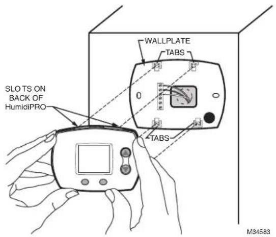
Mount Humidity Control
Align the 4 tabs on the wallplate with the slots on the back of the control, then push gently until the control snaps in place.
text_image
SLOTS ON BACK OF HumidiPRO WALLPLATE TABS 0 TABS M34583Checkout
Allow C7089 Outdoor Sensor to absorb outdoor air for a minimum of twenty minutes before taking a reading. With an accurate thermometer ( ±1^ F [0.5°C]), measure the temperature at the sensor location, allowing time for the thermometer to stabilize before reading.
Then verify the sensor accuracy by going into installer Test #20. This will show you the outdoor temperature.
Calibration
The C7089 Outdoor Sensor is calibrated at the factory. However, you can offset the outdoor sensor reading using Function 35 in Installer Setup.
You've just installed your Humidity Controller!
This Humidity Control has been preprogrammed to the ideal settings for most homes.
If you installed this control with an outdoor sensor, the control will operate in AUTOMATIC MODE, which automatically adjusts humidity to help prevent window condensation.
If you installed this control without an outdoor sensor, the control will operate in MANUAL MODE, giving the homeowner simple, direct control of their humidifier (RH% Setting Only).
Advanced Installer Setup
See next page to customize feature operation.
Installer System Test
If Advanced Installer Setup is not required, skip to "Installer System Test/Checkout" on page 19.
Advanced Installer Setup
Resideo has already programmed this control to work properly in most applications. However, you can adjust the advanced settings by following the steps below.
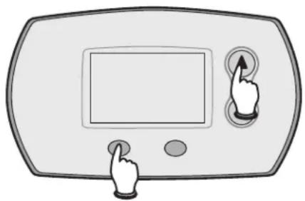
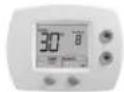
To begin, press and hold the ▲ and LIGHT buttons until the display changes.
Press ▲ or ▼ to change settings.
Press NEXT to advance to the next function.
Press DONE to exit and save settings.
natural_image
Illustration of a digital display with two buttons and a finger pointing at it (no text or symbols)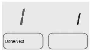
text_image
DoneNextM29387A
| Function Number | Setting | |
| Displayed Description | ||
| 1 System Type | 1 Humidifier | |
| 2 Dehumidifier | ||
| 4 Control ModeAutomatic Mode is Default when Outdoor Sensor DetectedManual Mode is Default when NO Outdoor Sensor Detected | 1 Automatic | |
| 2 Manual | ||
| 5 Automatic Mode RH% (Hum)This is the humidity setpoint (RH%) the control will operate to.The homeowner does not change this and will only need to set the appropriate window protection setting. | Range: 20%-60%Default = 35% | |
| 11 Automatic Mode Humidity BoostIncreases Preset RH% (#5) when user sets window protection to 11. | 0 Off | |
| 5% 5% | ||
| 10% 10% | ||
| 17 Automatic Mode High Temp Shut-OffTurns humidifier OFF when Outdoor Temperature is greater than selected setting. | Range: 40°-90°0 = OFFDefault = 65° | |
| 19 High Hum Limit | Range: 10%-90%Default = 60% | |
| 20 Low Hum Limit | Range: 10%-90%Default = 10% | |
| 21 High Dehum Limit | Range: 10%-90%Default = 80% | |
| 23 Low Dehum Limit | Range: 10%-90%Default = 40% | |
| 25 Dehumidifier Compressor Lockout | 0-5 MinutesDefault = 0 Minutes (OFF) | |
| 30 Humidity Sensing CalibrationIncreases Preset RH% (#5) when user sets window protection to 11. | Range: -9% to +9%Default = 0 (Displays Actual RH%) | |
| 35 Outdoor Temperature Sensor CalibrationThis feature will offset the sensed outdoor temperature if needed. | Range: -9° to +9°Default = 0 (Displays Actual Outdoor Temp) | |
HumidPRO™ Frost Index
| Outdoor Temp | ||||||||||||
| -10°F 0°F | 10°F 20°F | 30°F 40°F | ||||||||||
| Frost Index | 1 | 10 | 10 | 10 | 10 | 11 | 11 | 17 | 17 | 25 | 25 | 35 36 |
| 2 | 10 | 10 | 10 | 10 | 15 | 15 | 21 | 21 | 29 | 29 | 35 39 | |
| 3 | 10 | 10 | 14 | 14 | 19 | 19 | 26 | 26 | 34 | 34 | 35 46 | |
| 4 | 15 | 15 | 19 | 19 | 25 | 25 | 32 | 32 | 35 | 39 | 35 52 | |
| 5 | 21 | 21 | 26 | 26 | 32 | 32 | 35 | 38 | 35 | 48 | 35 58 | |
| 6 | 29 | 29 | 34 | 34 | 35 | 39 | 35 | 48 | 35 | 56 | 35 60 | |
| 7 | 35 | 39 | 35 | 46 | 35 | 52 | 35 | 58 | 35 | 60 | 35 60 | |
| 8* | 35 | 56 | 35 | 60 | 35 | 60 | 35 | 60 | 35 | 60 | 35 60 | |
| 9 | 35 | 60 | 35 | 60 | 35 | 60 | 35 | 60 | 35 | 60 | 35 60 | |
| 10 | 35 | 60 | 35 | 60 | 35 | 60 | 35 | 60 | 35 | 60 | 35 60 | |
*Black Numbers show highest humidity allowed when Default RH% (35%) is Selected.
Note: Smaller grey numbers show highest humidity allowed when Maximum RH% (60%) is selected.
Installer System Test/Checkout
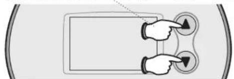
To begin, press and hold the ▲ and ▼ buttons until the display changes.
natural_image
Diagram showing two hands interacting with a device, one pointing at a button and the other down-right, both connected to a circular interface (no text or symbols)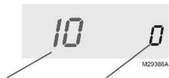
text_image
10 0 M29388ATest number System status
Press ▲ / ▼ to turn system on/off. Press NEXT to advance to next test. Press DONE to terminate system test.
| Function Number | Setting | |
| Number Description | ||
| 10 System Test | 0 | OFF |
| 1 | ON | |
| 20 View Outdoor Temperature | Shows Outdoor Temperature | |
NOTE: Make sure to turn on the system fan when testing humidifier operation.
H6062 Specifications
Humidity Ranges:
Humidify:
- Default: 10% to 60%
• Total Range Available: 10% to 90%
Operating Ambient Temperature
• 32° to 120°F (0° to 48.9°C)
Operating Relative Humidity
• 5% to 90% (non-condensing)
Startup and Checkout
When installation is complete, follow the steps below. Make sure the humidifier is running properly before turning the system over to the homeowner. Once the humidifier is running, day-to-day operation is automatic. The homeowner can use the control to adjust the humidity levels and turn the humidifier on or off.
text_image
Technical diagram showing cable installation components with numbered labels and a magnified inset of the device's cable connection.Snap the bottom cover into place.
Turn on the water supply at the saddle valve or T-fitting and manual shutoff valve. Water will flow to the humidifier but will not pass through the pad until the humidity control is turned on.
Turn on power to the transformer that powers the humidifier.
Turn the Damper Position knob on the bypass outlet so that it is parallel to the bypass outlet.
Turn the humidity control to On.
- If your wiring is configured for operation only with heat or fan, make the appropriate system demands to allow humidification.
- Make sure air is blowing through the ductwork with the humidifier call.
Remove the humidifier's top cover to verify water flow through the top tray and into the pad.
Check all water line and drain connections to ensure there are no leaks before leaving the job site.
- Check for leaks immediately after turning the main water supply on, and again after 15 minutes of humidifier operation.
Turn the setpoint to the homeowner's desired level when testing is complete. If humidity is not needed, set the control to Off, and turn the Damper Position knob on the bypass outlet so that it is perpendicular to the bypass outlet.
Routine Maintenance
The humidifier pad should be replaced at least once per year. This is critical for optimal performance of the unit. This can be done at the beginning or the end of the dry season. The humidifier design makes this annual replacement quick and easy, providing one-step access to the pad.
- Pad can be replaced from the side by gripping the black handle and pulling out, or from the front by removing the humidifier's top cover and rocking the pad forward and out Humidifier pad might remove from other side of humidifier, depending on installation.
- Remove tray on top of the pad, and wipe free any sediment present within the tray.
- Replace the old pad with the new, making sure pad is oriented correctly (see pad box). Wipe free any sediment present inside the pad frame.
- Reseat the tray on top of the pad with the arrows inside the tray pointing into the duct. Then reinsert the frame into the humidifier.
natural_image
3D rendering of a mechanical component with cylindrical and rectangular parts, no visible text or symbols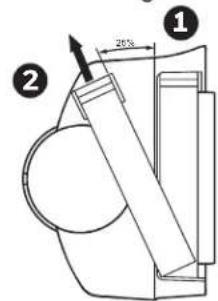
text_image
20% ① ②MCR29685
Troubleshooting
Problem What To Look For What To Do
| Low humidity Furnace blower not operating | 1. Reset circuit breaker or check for blown fuse.2. Check that the furnace power is on.3. Check all external wiring connections.4. Check the humidity control setting. |
| Rapid air changes or drafts | 1. Keep doors and windows closed.2. Close fireplace damper when not in use.3. Keep exhaust fan running time to a minimum.4. Seal around doors and windows. |
| High humidity Condensation on walls 1. Turn off humidity control and water until condensation is completely evaporated. | |
| Heavy condensation on windows | 1. Turn humidity control down low enough to eliminate condensation caused by moisture. If moisture persists, more ventilation is needed. |
A: Specifications
Humidifying Capacity
At 120°F (49°C) plenum temperature and 0.20 static pressure drop across supply and return: Up to 17 gpd (65 lpd)
Humidified Area
Up to 20,000 cubic feet
Dimensions
15 in. W x 17.15 in. H x 10.1 in. D (381 mm W x 436 mm H x 257 mm D)
Humidifier Pad Dimensions
10 in. W x 13 in. H x 1-1/2 in. D (254 mm W x 330 mm H x 38 mm D)
Static Pressure
Supply plenum static pressure no greater than .3 in. w.c.
Plenum Opening Dimensions
9-3/4 in. W x 12-5/8 in. H (248 mm W x 321 mm D)
Bypass Duct Opening Dimensions
6 in. (152 mm)
Operating Ranges
34°F–90°F (1.1°C–32°C) Humidity: 0–95% RH, non-condensing
Drain Fitting
1/2 in. (13 mm) I.D. plastic hose connected directly to drain fitting on unit.
Electrical Ratings and Tolerances
HE400: 24VAC, 60 Hz, 0.75 A maximum
B: Advanced Draining
flowchart
graph TD
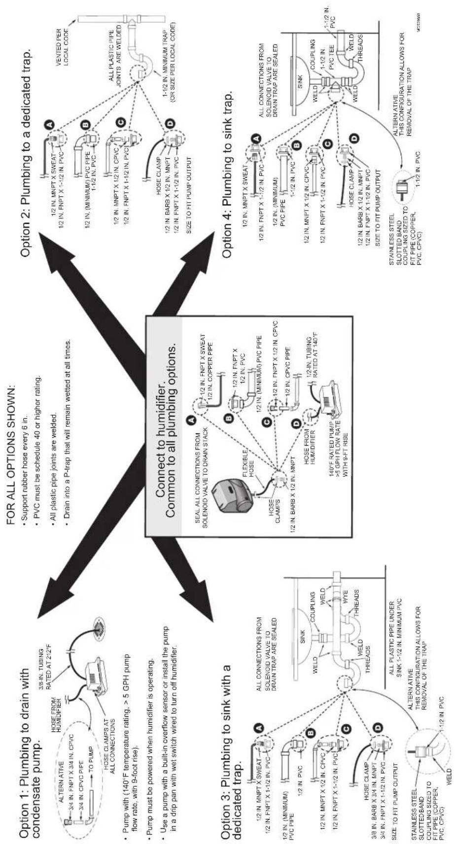
A["Option 1: Plumbing to drain with condensate pump."] --> B["FOR ALL OPTIONS SHOWN:"]
B --> C["Option 2: Plumbing to a dedicated trap."]
C --> D["Option 3: Plumbing to sink with a dedicated trap."]
D --> E["Option 4: Plumbing to sink trap."]
subgraph A
F["ALTERN ATIVE"] --> G["3/4 IN. FNPT X 3/4 IN. CPVC"]
H["3/4 IN. CPVC PIPE"] --> I["TO PUMP"]
J["HOSE CLAMPS AT ALL CONNECTIONS"] --> K["Pump with (140°F temperature rating, >5 GPH pump flow rate, with 9-foot rise)."]
L["Pump must be powered when humidifier is operating."] --> M["Use a pump with a built-in overflow sensor or install the pump in a drip pan with wet switch wired to turn off humidifier."]
end
subgraph B
N["FOR ALL OPTIONS SHOWN:"]
O["• Support rubber hose every 6 in."]
P["PVC must be schedule 40 or higher rating."]
Q["All plastic pipe joints are welded."]
R["Drain into a P-trap that will remain wetted at all times."]
end
subgraph C
S["• VENTED PER LOCAL CODE"] --> T["1/2 IN. MNPT X SWEAT"]
U["1/2 IN. FNPT X 1-1/2 IN. PVC"] --> V["1/2 IN. (MINIMUM) PVC PIPE"]
W["1-1/2 IN. PVC"] --> X["1/2 IN. MINNPT X 1/2 IN. CPVC"]
Y["1/2 IN. FNPT X 1-1/2 IN. PVC"] --> Z["1/2 IN. MINNPT X 1-1/2 IN. PVC"]
AA["HOSE CLAMP"] --> AB["1/2 IN. BARB X 1/2 IN. MINPT"]
AC["1/2 IN. FNPT X 1-1/2 IN. PVC"] --> AD["1/2 IN. MINNPT X 1-1/2 IN. PVC"]
AE["SIZE TO FIT PUMP OUTPUT"] --> AF["1-1/2 IN. MINNPT X 1-1/2 IN. PVC"]
AG["SINK 1-1/2 IN. MINNPT X 1-1/2 IN. PVC"] --> AH["1/2 IN. MINNPT X 1-1/2 IN. PVC"]
AI["WELD"] --> AJ["1-1/2 IN. MINNPT X 1-1/2 IN. PVC"]
AK["SINK 1-1/2 IN. MINNPT X 1-1/2 IN. PVC"] --> AL["1/2 IN. MINNPT X 1-1/2 IN. PVC"]
AM["WELD"] --> AN["1-1/2 IN. MINNPT X 1-1/2 IN. PVC"]
AO["SINK 1-1/2 IN. MINNPT X 1-1/2 IN. PVC"] --> AP["1/2 IN. MINNPT X 1-1/2 IN. PVC"]
AQ["SINK"] --> AR["1-1/2 IN. MINNPT X 1-1/2 IN. PVC"]
AS["SINK"] --> AT["1-1/2 IN. MINNPT X 1-1/2 IN. PVC"]
AU["SINK"] --> AV["1-1/2 IN. MINNPT X 1-1/2 IN. PVC"]
AW["SINK"] --> AX["1-1/2 IN. MINNPT X 1-1/2 IN. PVC"]
AY["SINK"] --> AZ["1-1/2 IN. MINNPT X 1-1/2 IN. PVC"]
BA["SINK"] --> BB["1-1/2 IN. MINNPT X 1-1/2 IN. PVC"]
BC["SINK"] --> BD["1-1/2 IN. MINNPT X 1-1/2 IN. PVC"]
BE["SINK"] --> BF["1-1/2 IN. MINNPT X 1-1/2 IN. PVC"]
BG["SINK"] --> BH["1-1/2 IN. MINNPT X 1-1/2 IN. PVC"]
BI["SINK"] --> BJ["1-1/2 IN. MINNPT X 1-1/2 IN. PVC"]
BK["SINK"] --> BL["1-1/2 IN. MINNPT X 1-1/2 IN. PVC"]
BM["SINK"] --> BN["1-1/2 IN. MINNPT X 1-1/2 IN. PVC"]
BO["SINK"] --> BP["1-1/2 IN. MINNPT X 1-1/2 IN. PVC"]
BQ["SINK"] --> BR["1-1/2 IN. MINNPT X 1-1/2 IN. PVC"]
BS["SINK"] --> BT["1-1/2 IN. MINNPT X 1-1/2 IN. PVC"]
BU["SINK"] --> BV["1-1/2 IN. MINNPT X 1-1/2 IN. PVC"]
BW["SINK"] --> BX["1-1/2 IN. MINNPT X 1-1/2 IN. PVC"]
BY["SINK"] --> BZ["SINK"] --> CA["SINK"]
end
C: Parts List
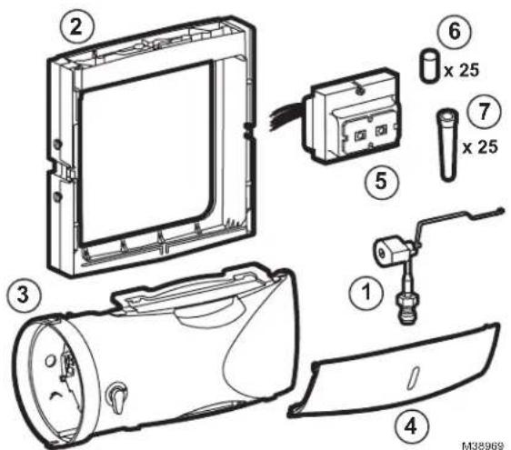
text_image
Exploded view diagram of a device with numbered parts and labeled components| Figure Reference Part Number Part Description | |
| N/A HC26E1004 Large AgION coated replacement pad | |
| N/A HC26A1008 Large standard replacement pad | |
| N/A 32001616-001 Saddle valve | |
| 1 50041883-002 AC Solenoid valve | |
| 2 50041861-002 Frame and tray assembly | |
| 3 Bypass duct connection | |
| 4 Bottom cover | |
| 5 32001652-001 24 VAC, 10VA transformer | |
| 6 32318545-001 Qty 25 Residential humidifier quick connect adapter | |
| 7 32001647-001 Qty 25 Residential humidifier cone screen filter |

resideo
Resideo Inc., 1985 Douglas Drive North.
Golden Valley, MN 55422
Honeywell Home
www.resideo.com
33-00617EFS-03 S.A. 04-23 | Printed in United States
© 2023 Resideo Technologies, Inc. All rights reserved. The Honeywell Home trademark is used under license from Honeywell International, Inc. This product is manufactured by Resideo Technologies, Inc. and its affiliates.
natural_image
3D rendered image of a gray mechanical component with a curved cutaway view (no text or symbols visible)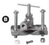

E

G
natural_image
3D technical illustration of a mechanical pipe assembly inside a housing (no text or symbols)text_image
Technical diagram showing labeled components of a wall or ceiling fixture with numbered annotationsMCR29877
text_image
Technical diagram of a device with labeled components and directional arrows indicating flow or movementtext_image
Technical diagram of a mechanical device with labeled parts and assembly instructionstext_image
Technical diagram showing a device with three labeled parts: connection to cable, valve assembly, and adjustment mechanism.natural_image
Diagram showing a window and door with cross symbols, no readable text or labels presentnatural_image
Illustration of a hand holding a handheld electric drill (no text or symbols)natural_image
Technical diagram of a mechanical component with labeled parts (no readable text or symbols)text_image
Diagram illustrating window frame structure with angle measurement and directional arrow, showing measurements like 40° and 30°.M7514A
natural_image
Illustration of a digital device with a screen and two buttons, no text or symbols present
text_image
DoneNextM29387A
text_image
Technical diagram showing labeled components of a mechanical or electrical device with numbered parts and magnified views.natural_image
3D mechanical component diagram showing a cylindrical housing with mounting holes and a side panel (no text or symbols)
text_image
Technical diagram showing a mechanical assembly with labeled parts and a 20-degree angle indicatorMCR29885
Dépannage
text_image
Exploded view diagram of a device with numbered parts and labeled componentsResideo Inc., 1985 Douglas Drive North,
Golden Valley, MN 55422
www.resideo.com
© 2023 Resideo Technologies, Inc. All rights reserved. The Honeywell Home trademark is used under license from Honeywell International, Inc. This product is manufactured by Resideo Technologies, Inc. and its affiliates.
natural_image
3D rendered image of a gray mechanical component with a curved cutout and mounting holes (no text or symbols visible)
E

G
natural_image
3D technical illustration of a mechanical assembly with pipe connection (no text or symbols)text_image
M29873 ③ ① M32800 DESVÍO 1/2 (13) ② A-COIL MS29874Atext_image
Technical diagram of a mechanical device with labeled parts and assembly instructionstext_image
Technical diagram showing a device with three labeled parts: connection, assembly, and adjustment mechanism.natural_image
Diagram showing a room with a window, door, and wall, marked with X marks (no text or symbols)natural_image
Illustration of a hand holding a handheld electric drill (no text or symbols)natural_image
Technical line drawing of a mechanical component with no visible text or symbolstext_image
Diagram illustrating window frame installation with magnified detail and directional arrow, showing structural components and component placement.natural_image
Illustration of a digital display with two buttons and a finger pointing at it (no text or symbols)
text_image
DoneNextM29387A
text_image
Technical diagram showing cable installation components with numbered labels and a MCR34841 label at the bottom.natural_image
3D mechanical component diagram showing a cylindrical housing with a side panel and directional arrow (no text or symbols)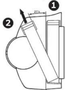
text_image
Technical diagram showing a mechanical assembly with labeled components and dimension annotationMCR29885
text_image
Exploded view diagram of a device with numbered parts and labeled componentsResideo Inc., 1985 Douglas Drive North,
Golden Valley, MN 55422
www.resideo.com
© 2023 Resideo Technologies, Inc. All rights reserved. The Honeywell Home trademark is used under license from Honeywell International, Inc. This product is manufactured by Resideo Technologies, Inc. and its affiliates.