H8908B - Humidifier HONEYWELL - Free user manual and instructions
Find the device manual for free H8908B HONEYWELL in PDF.
Download the instructions for your Humidifier in PDF format for free! Find your manual H8908B - HONEYWELL and take your electronic device back in hand. On this page are published all the documents necessary for the use of your device. H8908B by HONEYWELL.
USER MANUAL H8908B HONEYWELL
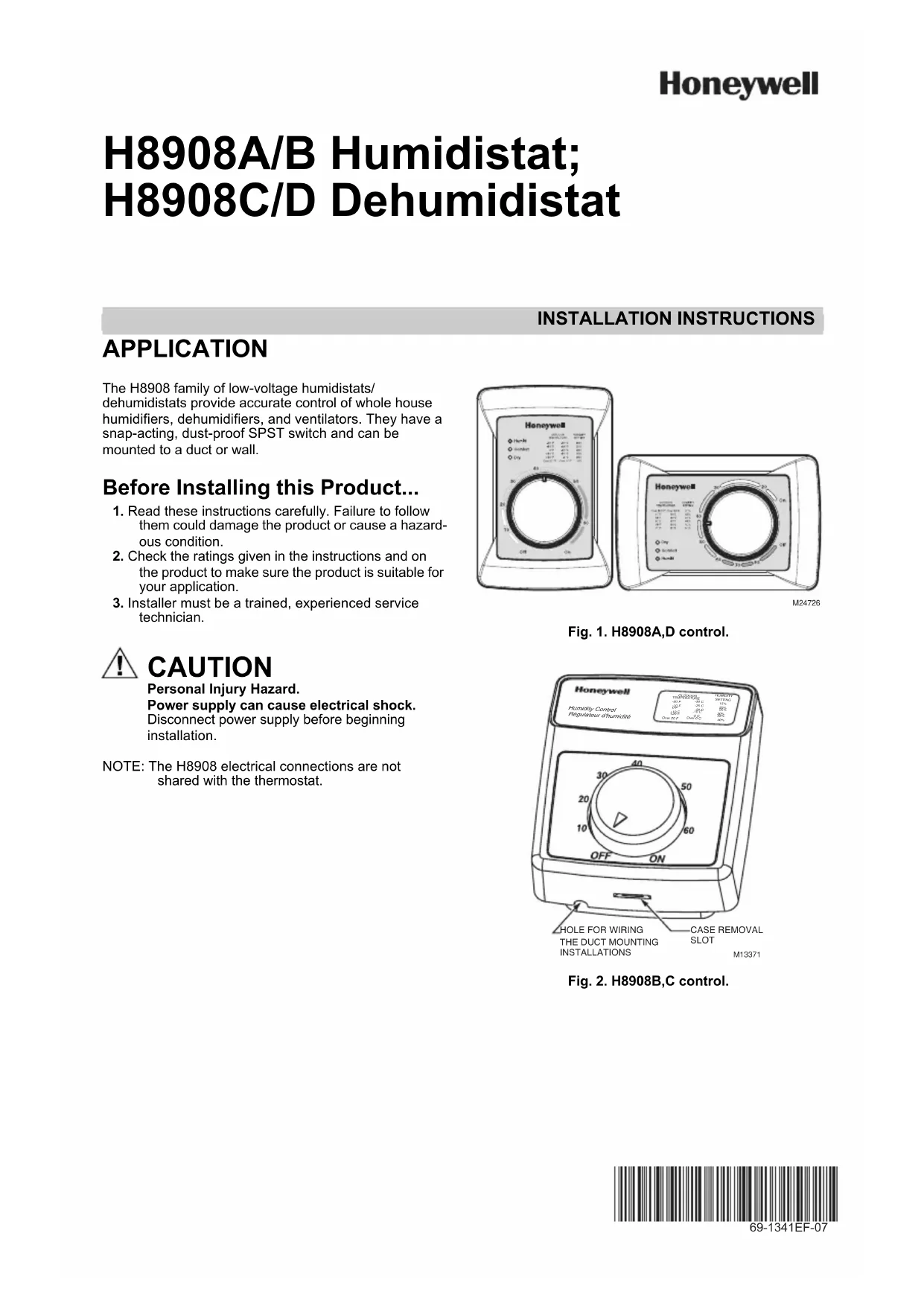
INSTALLATION INSTRUCTIONS Place Bar Code Here 69-1341EF-07 H8908A/B Humidistat; H8908C/D Dehumidistat APPLICATION The H8908 family of low-voltage humidistats/dehumidistats provide accurate control of whole house humidifiers, dehumidifiers, and ventilators. They have a snap-acting, dust-proof SPST switch and can be mounted to a duct or wall. Before Installing this Product... 1. Read these instructions carefully. Failure to follow them could damage the product or cause a hazard-ous condition.2. Check the ratings given in the instructions and on the product to make sure the product is suitable for your application.3. Installer must be a trained, experienced service technician. CAUTION Personal Injury Hazard.Power supply can cause electrical shock.Disconnect power supply before beginning installation.NOTE: The H8908 electrical connections are not shared with the thermostat.Fig. 1. H8908A,D control.Fig. 2. H8908B,C control.M24726Humidity ControlRégulateur d'humidité-20 F-10 F 0 F +10 F+20 FOver 20 F 15% 20% 25% 30% 35% 40%
1. Choose a location on the duct.
Fig. 3. Duct installation locations.
2. Apply sticker template to duct and drill holes for
mounting screws. Cut along the dotted line of the template with metal shears or tin snips. Fig. 4. Drill and cut holes in duct.
3. Run two-fan, low-voltage wire to the mounting loca-
tion on the duct. See Fig. 5. IMPORTANT Use rated 18-22 gauge wire. Leave approximately 6 in. of wire to properly connect the humidistat. Fig. 5. Run wire to the mounting location. REMOTE MOUNT INSTALLATION
1. Choose a location in the living area.
NOTE: Select a location clear of drafts or excessive humidity. Avoid mounting near doors or win- dows, or in bathrooms or kitchens. See Fig. 6. Fig. 6. Choose a location in the living area.
2. Cut 1 in. diameter wire hole in wall.
3. Run two-fan, low-voltage wire to the mounting loca-
tion in the living area. IMPORTANT Use rated 18-22 gauge wire. Leave approxi- mately 6 in. of wire to properly connect the humi- distat. Fig. 7. Run wire to the mounting location. ALTERNATE LOCATION RETURN AIR RETURN AIR 6 in. (152 mm) MINIMUM 15 in. (381 mm) MINIMUM BEST LOCATION
TWO-FAN 18-22 GAUGE WIRE
duct mount, slide the black gasket onto the base bracket. See Fig. 8. NOTE: Use gasket only when mounting the control to ductwork. Leave off when mounting to a wall. Fig. 8. Seal base bracket.
5. Secure the base bracket to the duct or remote loca-
tion. Secure to the duct with four 1-in. (25 mm) screws (provided) or to the wall with two 1-in. (25 mm) screws (provided). Fig. 9. Mount base bracket to duct or remote location. M24733 M24722H8908A/B HUMIDISTAT; H8908C/D DEHUMIDISTAT 69-1341EF—07 4 WIRING CAUTION Personal Injury Hazard. Can cause electrical shock and injury. Disconnect power before installation or servicing. All wiring must comply with applicable local codes, ordinances and regulations. Make wiring connections according to humidifier (or dehumidifier/ventilator) instructions, if available; otherwise, see typical wiring diagrams in Fig. 12–19. IMPORTANT Select models of fan centers include humidifier taps so the current sensing relay, sail switch or air pressure switch is not needed. If not using a current sensing relay, sail switch, or air pressure switch, the humidifier must be energized during blower motor cycles for proper operation. On multispeed blower applications, do not wire the high voltage side of the transformer to the same power source that services the furnace blower. Premature transformer burnout can occur. On HE365 fan powered humidifier mod- els, only the two yellow wires are connected to the control. The remaining two red wires are only used with electronic humidity controls.
6. Using wire nuts, connect the low-voltage wire to the
leads on the H8908 humidistat. See Fig. 6–19 for different wiring configurations. Fig. 10. Wire the humidistat.
7. Mount the humidistat by hooking the two hinges at
the top of the back cover to the raised edge at the top of the base bracket. Press the bottom of the humidistat in to engage the base hinge. You will hear a “click” when the humidistat is secured. Fig. 11. Attach the humidistat to the base. Fig. 12. Wiring H8908 with fan interlock. Fig. 13. Wiring H8908 with 2-speed fan motor. Fig. 14. Typical wiring diagram of current sensing relay with humidifier. M24734M24801 H8908
HE225/HE265 HUMIDIFIER STAGE 1 HEAT STAGE 2 HEAT COMPRESSOR C7089U1006 FAN RELAY HEATING RELAY OR VALVE COIL COOLING CONTACTOR COIL FAN RELAY COIL
60H8908A/B HUMIDISTAT; H8908C/D DEHUMIDISTAT 69-1341EF—07 6 CHECKOUT Turn the H8908 dial to “ON” to test proper installation. See Fig. 20. You will hear an audible click if installed correctly, and water will begin flowing to the humidifier. Fig. 20. Turn humidistat on. OPERATION Humidity Control Adjustment To maintain optimal humidity levels without causing condensation on cold surfaces such as windows, the homeowner must adjust the setpoint as the outdoor temperature changes. To reduce the relative humidity, lower the setpoint approximately three percent relative humidity every 24 hours. To increase the relative humidity, increase the setpoint approximately three percent relative humidity every 24 hours. Setpoint Adjustment Set the humidity setpoint according to the prevailing outdoor temperature. Recommended settings are available on the control and in the table below. Table 1. Recommended Humidity Controller Settings. M24723 Humidity ControlRégulateur d'humidité-20 F-10 F0 F+10 F+20 F Over 20 F 15% 20% 25% 30% 35% 40% HUMIDITY SET TINGOUTDOO