MC2430N10-B - Solar regulator Vevor - Free user manual and instructions
Find the device manual for free MC2430N10-B Vevor in PDF.

| Product Type | MPPT Solar Charge Controller |
| Brand | Vevor |
| Model | MC2430N10-B |
| System Voltage | 12 V / 24 V (auto recognition) |
| Rated Charge Current | 30 A |
| Max PV Power | 400 W (12 V) / 800 W (24 V) |
| Max PV Open Circuit Voltage | 92 V (25 °C); 100 V (low temperature) |
| MPPT Voltage Range | (Battery voltage + 2 V) ~ 72 V |
| MPPT Tracking Efficiency | > 99% |
| Conversion Efficiency | ≤ 98% |
| Self-consumption | < 10 mA |
| Supported Battery Types | Sealed lead-acid, gel, vented, lithium (LiFePO4 12/24V), custom |
| Temperature Compensation | -3 mV/°C/2V (default, not for lithium) |
| Built-in Protections | Battery and PV reverse polarity, PV short circuit, PV overvoltage, overheating, TVS lightning, night discharge |
| Protection Rating | IP32 |
| Operating Temperature | -35°C to 45°C |
| Communication Interface | TTL serial, optional Bluetooth BT-2 and CAN |
| Display | LEDs (charge status, battery, battery type) + optional external LCD |
| Dimensions (L × H × W) | 150 × 105.6 × 67.5 mm |
| Weight | 830 g |
| Maximum Altitude | 3000 m |
Frequently Asked Questions - MC2430N10-B Vevor
User questions about MC2430N10-B Vevor
0 question about this device. Answer the ones you know or ask your own.
Ask a new question about this device
Download the instructions for your Solar regulator in PDF format for free! Find your manual MC2430N10-B - Vevor and take your electronic device back in hand. On this page are published all the documents necessary for the use of your device. MC2430N10-B by Vevor.
USER MANUAL MC2430N10-B Vevor
Technical Support and E-Warranty Certificate www.vevor.com/support
MC SERIES MPPT SOLAR CHARGE
CONTROLLER MC2430N10-B/ MC2440N10-B/ MC2450N10-B
USER MANUAL
We continue to be committed to provide you tools with competitive price. "Save Half", "Half Price" or any other similar expressions used by us only represent estimate of savings you might benefit from buying certain tools with us compared top brands and does not necessarily mean to cover all categories of tools offered are kindly reminded to verify carefully when you are placing an order with us actually saving half in comparison with the top major brands.
MODEL:MC2430N10-B/ MC2440N10-B/ MC2450N10-B
NEED HELP? CONTACT US!
Have product questions? Need technical support? Please feel fr contact us:
Technical Support and E-Warranty Certificate www.vevor.com/support
This is the original instruction, please read all manual instruction carefully before operating. VEVOR reserves a clear interpretation user manual. The appearance of the product shall be subject to product you received. Please forgive us that we won't inform you there are any technology or software updates on our product.
 | Warning-To reduce the risk of injury, user must read instructions manual carefully. |
 | This device complies with Part 15 of the FCC Rules. Operat subject to the following two conditions:(1)This device may not harmful interference, and (2)this device must accept any inter received, including interference that may cause undesired oper |
 | This product is subject to the provision of European D 2012/19/EC. The symbol showing a wheelie bin crossed through indicates that the product requires separate refu collection in the European Union. This applies to the p and all accessories marked with this symbol. Products as such may not be discarded with normal domestic w must be taken to a collection point for recycling electri electronic devices |
| Model | MC2430N10-B | MC2440N10-B | MC2450N10-B |
| Battery voltage | 12V/24V | ||
| Max. PV open circ voltage | 92V(25°C); 100V(Lowest ambient temperature) | ||
| Charge current | 30A | 40A | 50A |
| Max. PV input pow | 400W/12V800W/24V | 550W/12V1100W/24V | 660W/12V1320W/24V |
Dear users, Thank you very much for choosing our products!
SAFETY INSTRUCTIONS
- Applicable voltage of the controller exceeds the safety voltage for body, so please read the manual carefully before use and operate th controller only after safety operation training has been completed.
- There are no parts inside the controller that need to be maintaine repaired. The user shall not disassemble and repair the controller.
- Install the controller indoors to prevent exposure of components and prevent water from entering the controller.
- Please install the controller in a well-ventilated place to prevent the sink from being overheated.
- It is recommended to install a proper fuse or circuit breaker outside controller.
- Be sure to disconnect the wiring of PV array and the fuse or cir breaker near battery terminal before installation and wiring adjustment the controller.
- Check that all wiring is tight after installation to avoid danger of the accumulation due to poor connections.

Warning: This operation is dangerous, so before operation, saf parations must be made.

Caution: This operation may have a destructive effect.

Reminder: Suggestions and tips for operator.
Table of Contents
- Introduction......05
- Installation....13
- Product Operation and Display....17
- Product Protection and System Maintenance....20
- Technical Parameters....23
- Conversion Efficiency Curve....25
- Product Dimensions....26
8.APP control function.... 27
1. INTRODUCTION
1.1 Overview
- With industry-leading PowerCatcher MPPT technology, the MC series solar charge controller enables maximum energy tracking for solar panels. This technology allows the controller to quickly and accurately track the maximum power point of PV array in any environment, the maximum energy of solar panels in real time, and significantly increase energy utilization efficiency of the solar energy system.
- This product can be connected to an external LCD screen or Blue communication module and PC Upper Computer for dynamic display of operating status, operating parameters, controller logs, control parameters, etc. The user can look up various parameters and can modify the control parameters as needed to suit different system requirements.
- The controller adopts standard Modbus communication protocol, which is convenient for the user to view and modify the parameter the system. Meanwhile, the company provides free monitoring software that can maximize the convenience for users to meet different needs of remote monitoring.
- The controller provides overall electronic fault self-test and powerful electronic protection functions which minimize components damage due to installation error and system failure.
1.2 Feature s
- PowerCatcher maximum power point tracking technology allows the controller to track the maximum power point of solar panels even complex environment. Compared with the traditional MPPT tracking technology, it boasts faster response speed and higher tracking efficiency.
● A built-in maximum power point tracking (MPPT) algorithm can significantly increase energy utilization efficiency of the photovoltaic
system, which is about 15% to 20% higher than traditional PWM charging.
- It provides an active charging voltage regulation feature. At battery open circuit or lithium battery BMS overcharge protection, the controller battery terminal will output the rated charging voltage val
● MPPT tracking efficiency is up to 99.9%.
- Due to advanced digital power technology, the circuit energy conversion efficiency is as high as 98%.
● Available in multiple battery types and support charging procedures various types of batteries such as lithium battery, colloidal battery, sealed battery, vented battery, lithium battery, etc.
- A current-limited charging mode is available. When the power of solar panel is too large and the charging current is higher than the radar valve, the controller automatically reduces the charging power so that the solar panel can operate at the rated charging current.
● Support automatic identification of lead-acid battery voltage.
- External LCD screen or Bluetooth module can be connected for viewing of equipment operating data and status, and modification of controller parameters is supported.
- Optional built-in Bluetooth function, which can view the running data and status of equipment and support the change of controller parameters.
- Optional built-in CAN function, which can view the running data and status of equipment and support the change of controller parameters
- Support standard Modbus protocol to meet communication needs in different occasions.
● Built-in over-temperature protection mechanism ensures that when temperature exceeds the set value of the device, the charging curve decreases linearly with the temperature, thereby reducing the temperature rise of controller and avoiding high temperature damage
● Temperature compensation and automatic adjustment of charge and discharge parameters help to improve battery life.
- Solar panel short circuit protection, battery open circuit protection ar TVS lightning protection, etc.
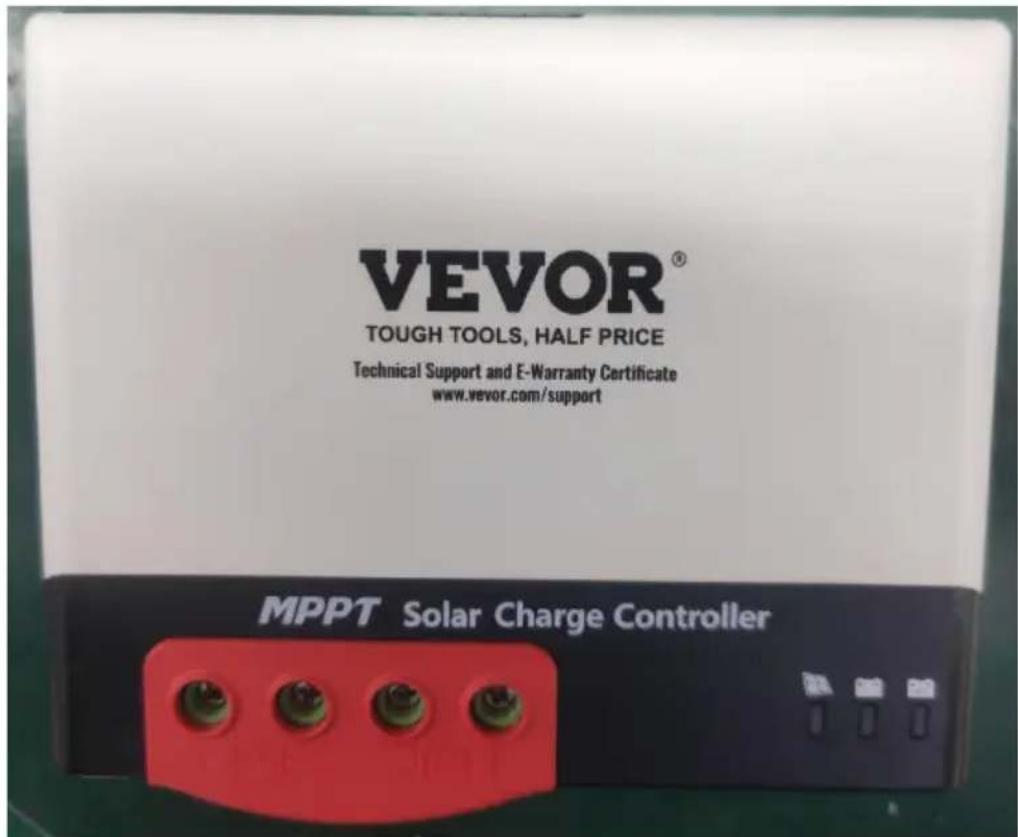
1.3 Appe arance

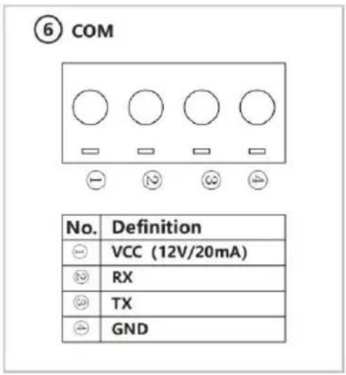
Figure 1-1 Controller Appearance and Ports
| No. | Names | No. | Names |
| 1 | Solar panel "+" interface | 6 | Communication Interface |
| 2 | Solar panel "-" interface | 7 | Operation keys |
| 3 | Battery "-" interface | 8 | PV charging indicator |
| 4 | Battery "+" interface | 9 | Battery level indicator |
| 5 | External temperature sampling interface | 10 | Battery type indicator |
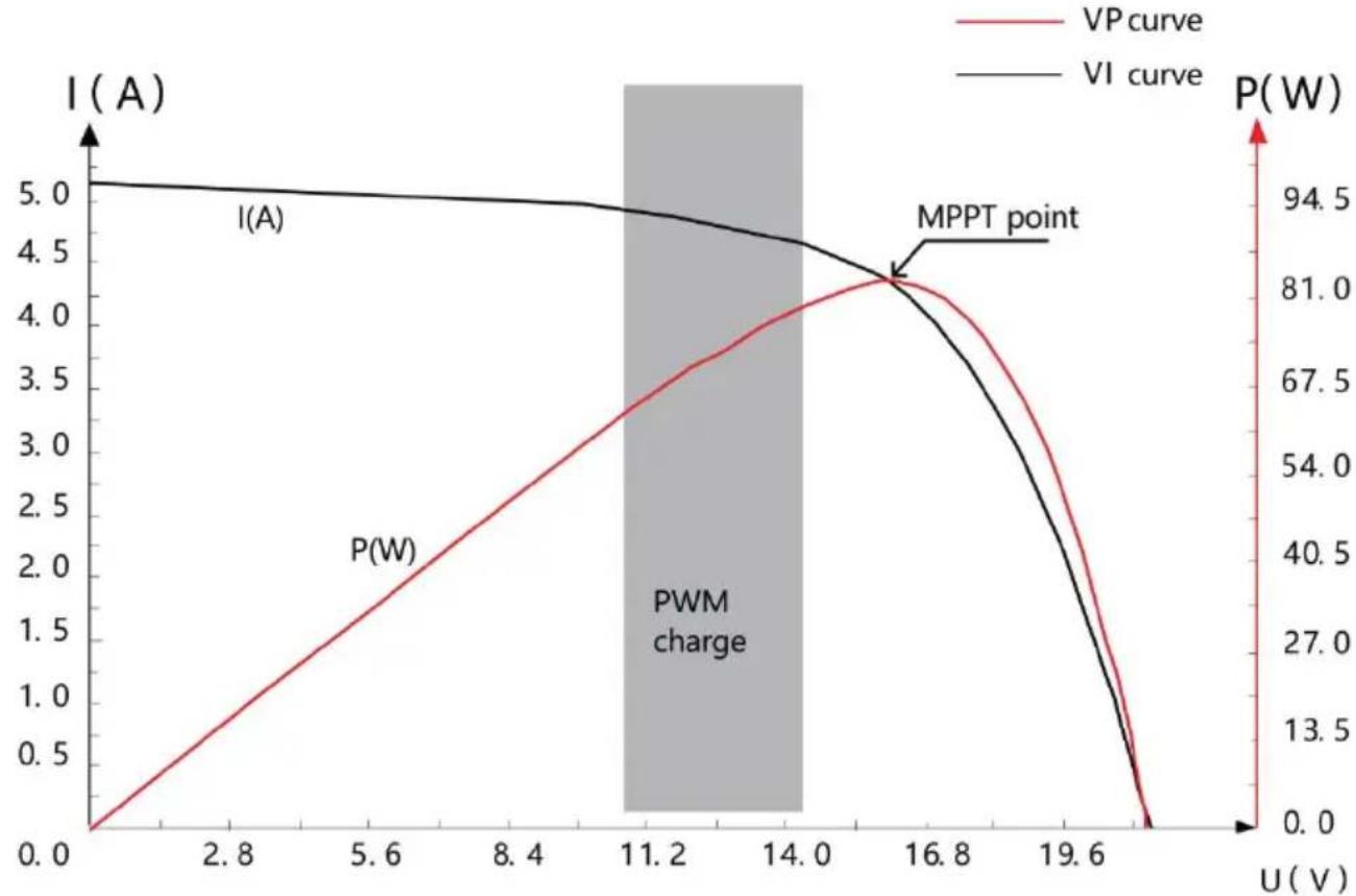
1.4 MP PT Technology Introductions
The Maximum Power Point Tracking (MPPT for short) system is an advanced charging technology that enables the solar panel to output more energy by adjusting operating conditions of the
electrical module. Due to the non-linear characteristics of solar arrays, there is a maximum energy output point (maximum power point) of a array on its curve. Traditional controller (switch charging technology an
PWM charging technology) fails to maintain battery charging at this pc and therefore the maximum energy of the solar panel cannot be obta. The solar charge controller with MPPT control technology, however, can track the array's maximum power point at all time to obtain the maxi energy to charge the battery.
Take a 12V system as an example. Peak voltage (Vpp) of the solar about 17V, while the battery voltage is about 12V. In general, when controller is charging the battery, the voltage of solar panel is about and does not fully contribute to its maximum power. But, MPPT contr can overcome this problem. It constantly adjusts the input voltage and current of the solar panel to achieve the maximum input power.
Compared to the traditional PWM controller, the MPPT controller can provide the maximum power of the solar panel and thus can provide larger charging current. In general, the MPPT controller can improve energy utilization by 15% -20% compared with the PWM controller.
bar_line
| U(V) | I(A) | P(W) | VP curve (W) | |------|------|------|--------------| | 0.0 | 5.0 | 0.0 | 0.0 | | 2.8 | 4.9 | 0.5 | 13.5 | | 5.6 | 4.8 | 1.0 | 27.0 | | 8.4 | 4.7 | 1.5 | 40.5 | | 11.2 | 4.6 | 2.0 | 54.0 | | 14.0 | 4.5 | 2.5 | 67.5 | | 16.8 | 4.4 | 3.0 | 81.0 | | 19.6 | 4.3 | 3.5 | 94.5 | | >19.6| 4.2 | 4.0 | ~94.5 |Figure 1-2 Solar panel output characteristics curve
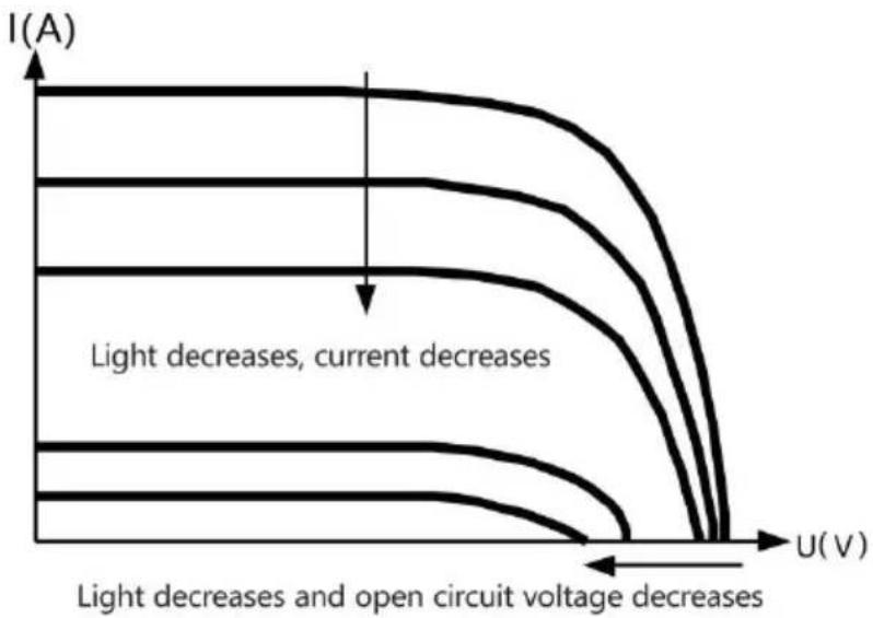
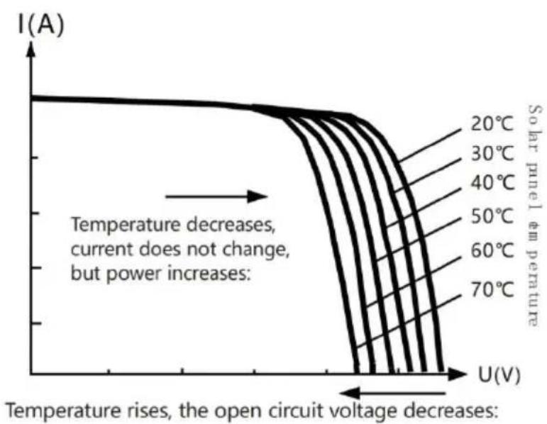
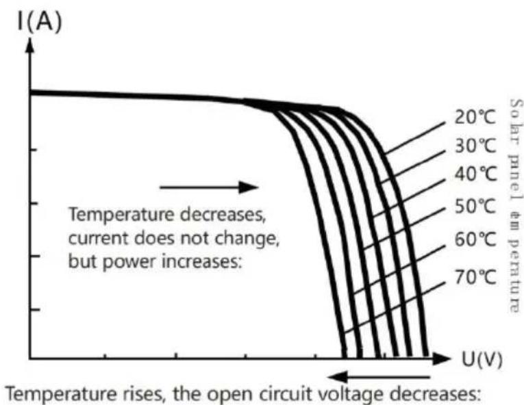
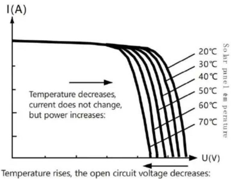
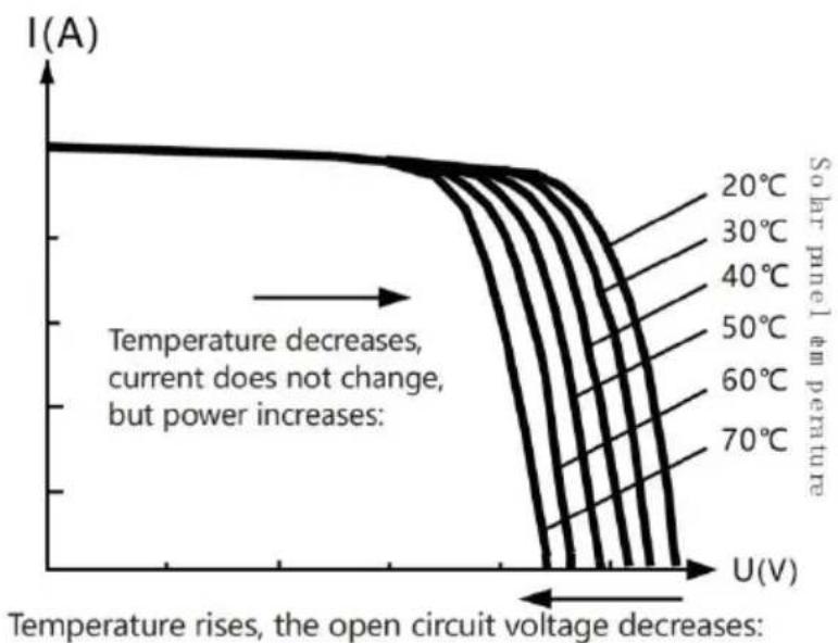
In addition, due to the difference in ambient temperature and light
conditions, the maximum power point often changes. The MPPT control can adjust parameters according to different conditions from time to time keep the system near its maximum working point. The whole process fully automatic and does not require any adjustments by users.
line
| U(V) | I(A) | |------|------| | Low | High | | Medium | Decreasing | | High | Decreasing |Figure 1-3 Relationship between solar panel output characteristics and light

line
| Temperature (°C) | Voltage (V) | Current (A) | | ---------------- | ----------- | ----------- | | 20 | ~0 | ~1.0 | | 30 | ~0 | ~0.8 | | 40 | ~0 | ~0.6 | | 50 | ~0 | ~0.4 | | 60 | ~0 | ~0.2 | | 70 | ~0 | ~0.1 |Figure 1-4 Relationship between solar panel output characteristics and temperature
1.5 Charging Stage Introd ucti ons
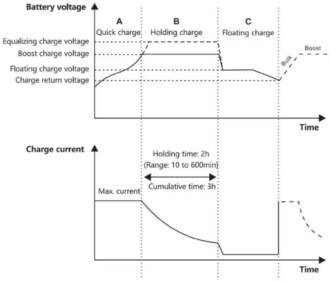
As one of the charging stages, MPPT cannot be used alone. It is required to combine boost charge, floating charge, equalizing charge a other charging methods to complete the battery charging process. A complete charging process includes: Quick charge, holding charge and floating charge. Charging curve is shown below:
line
| Time Segment | Battery Voltage | Charge Current | | ------------ | --------------- | -------------- | | A | Quick charge | Max. current | | B | Holding charge | 2h | | C | Floating charge | 3h |Figure 1-5 Battery charging stages curve graph
a) Quick charge
In quick charge stage, the battery voltage has not yet reached the s of full charge voltage (i.e. equalizing/boost charge voltage) and the controller will perform MPPT charging, which will provide maximum sol
energy to charge the battery. When the battery voltage reaches the p value, constant voltage charge will start.
b) Holding charge
When the battery voltage reaches the set value of holding voltage, the controller will perform constant voltage charging. This process will no longer include MPPT charging, and the charging current will gradually decrease with time. Holding charge comes in two stages, i.e. equalizing charge and boost charge. The two stages are conducted without repe in which equalizing charge is started once every 30 days.
▶ Boost charging
The default duration of boost charge is 2 hours. The customer can adjust the holding time and the pre-set value of boost voltage point according to actual needs. When the duration reaches the set value, system will switch to floating charge.
Equalizing charging

Warning: Risk of explosion!
Equalizing vented lead-acid batteries may generate explosive gases. So the battery compartment must be well ventilated.

Caution: Damage to the device!
Equalization can increase the battery voltage to levels that may damasensitive DC loads. It is necessary to verify that the allowable input of all system loads is greater than the equalizing charge set value.

Caution: Damage of device!
Over charge and excessive gas evolution may damage the battery plate and cause active substances on the battery plate to come off. Equali charge may cause damage if voltage is too high or time is too long carefully check the specific requirements of battery used in the system
Certain types of battery benefit from regular equalizing charge, which stir electrolytes, balance battery voltage, and complete chemical reactio Equalizing charge increases the battery voltage above standard voltage
causing vaporization of battery electrolyte. If it is detected that the control automatically controls the next stage to be equalizing charge, the equalizing charge will last for 120 minutes(default). The equalizing charge and boost charge are not repeated in a full charge process to avoid much gas evolution or battery overheating.
1) When the system cannot continuously stabilize the battery voltage a constant voltage due to the influence of installation environment or the controller will accumulate time until the battery voltage reaches the value. When the accumulated time reaches 3 hours, the system will automatically switch to floating charge.
2) If controller clock is not calibrated, the controller will perform reg equalizing charges according to its internal
Floating charging
Floating charge is conducted following the holding charge stage, where controller will reduce the battery voltage by reducing charge current and allowing the battery voltage to remain at the floating charge set value. During the floating charge stage, the battery is charged in a very low voltage to maintain full charge state of the battery. In this stage, the can get nearly all of the solar energy. If the load exceeds the energy solar panel can provide, the controller will not be able to maintain the battery voltage in the floating charge stage. When the battery voltage low as the recovery charge set point, the system will exit floating charge stage and re-enter the fast charge stage.
2. INSTALLATION
2.1 Inst all ation Prec aut ion
Be very careful when installing the battery. When installing the vented lead-acid battery, wear protective glasses. Once you touch the battery rinse it with clean water.
Avoid placing metal objects near the battery to prevent battery short Acid gas may be generated when the battery is charged. So ensure ventilation.
The battery may generate flammable gas. Please keep away from space. Avoid direct sunlight and infiltration of rainwater when installing outdoor water. Poor connection points and corroded wires may cause extreme heat to melt the wire insulation layer, burn the surrounding materials, and even cause fire. Therefore, it is necessary to ensure that the connectors are tightened, and the wires preferably fixed with a cable tie to avoid local connectors caused by wire shaking.
In system wiring, output voltage of the component may exceed the safety voltage of human body. So, it is necessary to use insulated tools and ensure that the hands are dry.
Battery terminal on the controller can be connected with either a single battery, or a pack of batteries. Subsequent instructions in the manual for a single battery, but it also applies to a battery pack.
Observe the safety recommendations of battery manufacturer.
The system connection wires are selected according to the current de of not more than 4A/mm2. Make the controller grounded.
2.2 Wiring Specificatio ns
Wiring and installation must comply with national and local electrical requirements.
PV and battery connection wires must be selected according to rated current. Refer to the following table for wiring specifications:
| Models | PV maximum Input current | Max. wire diameter at P end( mm^2/AWG ) | Rated charge current | Battery wire diameter ( mm^2/AWG ) |
| MC2430N10-B | 30 | 8/8 | 30A | 8/8 |
| MC2440N10-B | 40 | 10/7 | 40A | 10/7 |
| MC2450N10-B | 50 | 12/6 | 50A | 12/6 |
2.3 Inst all ation and Wiring

Warning: Danger, Explosion! Never install the controller and a vented battery in the same enclosed space! Also do not install in an enclosed place where battery gas may collect.

Warning: Danger, High Voltage! Photovoltaic arrays may generate very high open circuit voltages. Disconnect circuit breaker or fuse before wiring and be very careful during wiring.

Caution: When installing the controller, ensure that the enough air to flow through the controller's heat sink, leaving least 150mm above and belo the controller to ensure natur convection for heat dissipation install in a closed box, ensure reliable heat dissipation through the box.
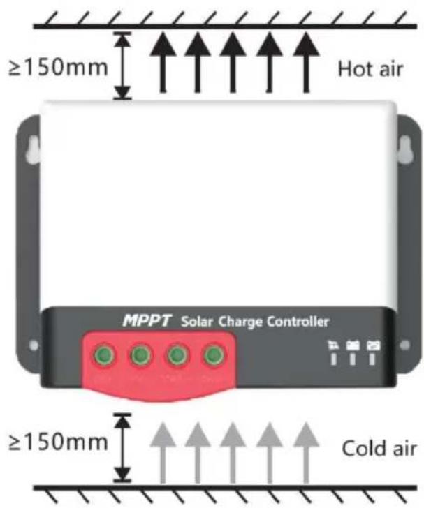
Figure 2.1 Installation and Heat Dissipation
Step 1: Choose an installation location
Avoid installing the controller in a place free of direct sunlight, high temperature, and water, and ensure good
ventilation around the controller.
Step 2: Mark the mounting position according to the mounting dimensions of the controller. Drill 4 mounting holes of the appropriate size at the 4 marks. Fix screws into the upper two mounting ho
Step 3: Fasten the Controller
Align fixing holes of the controller with the two pre-fixed screws and the controller up. And then fix the lower two screws.
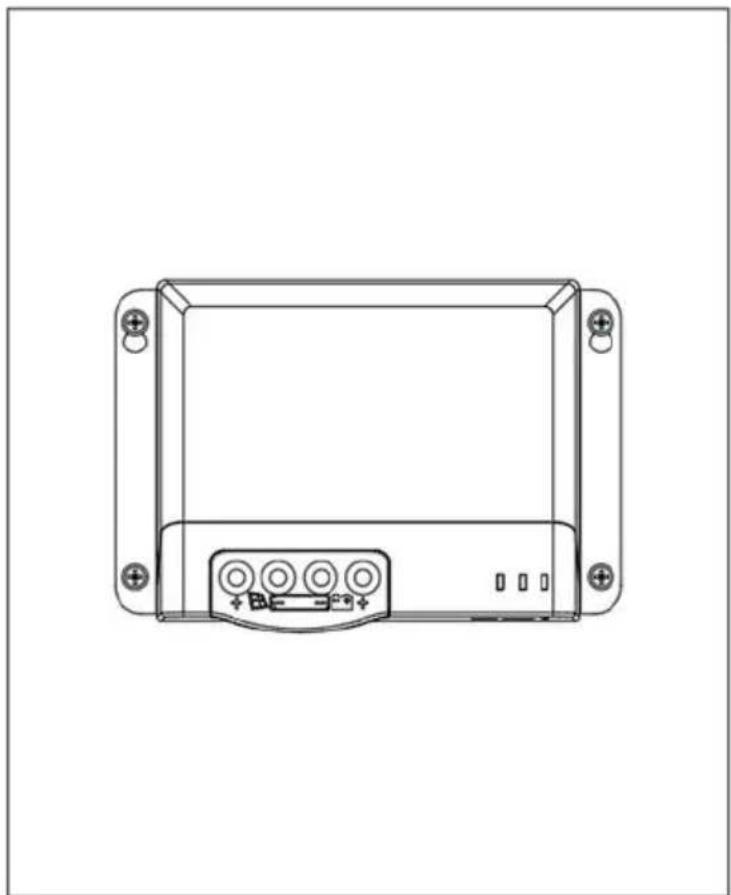
natural_image
Front view line drawing of a rectangular electronic device with mounting flanges and a central control panel (no text or symbols)Step 4: wire
For installation safety, we recommend a wiring sequence as follows; however, wiring in other sequences instead of this one will not damage controller.
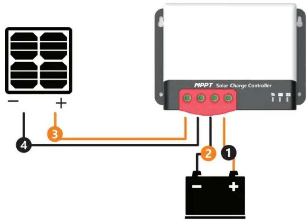
Warning: Danger, Electric shock hazards! We strongly recommend connect a fuse or circuit breaker to the PV array and battery terminal prevent electric shock hazards during wiring or error operation, and must ensure that fuse or circuit breaker is disconnected before wiring.
Warning: Danger, High voltage hazards! Photovoltaic arrays may generate very high open circuit voltages. Disconnect circuit breaker or before wiring and be very careful during wiring.
Warning: Danger, Explosion hazards! If the positive and negative terminals of battery and the wires connected to them are short-circuits may cause a fire or explosion. Please be very careful in operation. Please connect the battery first, and then the solar panel. Please follow “+” first and “-” next method when wiring.
When all wires are connected firmly and reliably, check whether the is proper and whether the polarity is reversed. After confirmation, con the battery fuse or circuit breaker and observe whether the LED indicator. If not, disconnect the fuse or circuit breaker immediately and check
whether wiring is correct.
As the battery is properly energized, connect the solar panel. If there sufficient sunlight, the charge indicator of controller will be steady on flash and start to charge the battery.

Warning: When the controller has stopped charging for 10 minutes reverse polarity of the battery can damage the controller's internal components.
Note:
1) Note that the battery fuse shall be installed as close as poss the battery terminal. The recommended distance is not more than 150mm.
2) The battery temperature is 25^ C (fixed value) when the control not collected to a remote temperature sensor.
3. PRODUCT OPERATION AND DISPLAY
3.1 LED Indic ator s
There are a total of three indicators on the controller
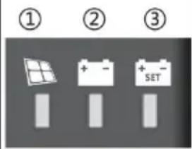 | 1 ---PV array indication | Indicate the current charging mode of controller |
| 2 ---BAT indication | Indicate the current state of battery. | |
| 3 ---BAT Type indication | Indicate the current battery ty |

PV array indicator:
| No. | CHARGE STATUS | Indicator state | Charging state |
| 1 |  | Steady on | MPPT charging |
| 2 |  | Slow flashing(On:1s, off: 1s, cycle: 2s) | Boost charging |
| 3 |  | Single flashing(On:0.1s, off: 1.9s, cycle: 2s) | Floating charging |
| 4 |  | Quick flashing(On:0.1s, off: 0.1s, cycle: 0s) | Equalizing charging |
| 5 |  | Double flashing(On:0.1s, off: 0.1s, then, On:0.1s, off: 1.7s, cycle: 0s) | Current-limited charging |
| 6 | Off | No charging |

BAT indicator:
| Indicator color | Indicator status | Battery status |
| Green | Steady on | Battery full charge |
| Yellow | Steady on | Battery voltage normal |
| Red | Steady on | Battery voltage below under-voltage point |
| Quick flash(On:0.1s, off: 0.1s, cycle: 0 | Battery over-voltage or over tempera |

BAT Type Indication:
| Indicator color | Battery status |
| Green | Sealed lead-acid battery |
| Yellow | Colloidal lead-acid battery |
| Red | Vented lead-acid battery |
| Blue | Lithium iron phosphate battery 12\ |
| Purple | Lithium iron phosphate battery 24\ |
| White | Custom |
3.2 Keys Operatio n
There is a key on the controller, which is used in conjunction with t battery type indicator for selection of battery type. The specific operati mode is as follows:
In the current operating state, press and hold the key for 8 seconds, battery type indicator (the color displayed is that of the previously saw battery type) starts to flash (the controller turns off charging and other works and enters an idle state). At this point, each time the key is the battery type indicator changes a color that corresponds to a battery type. After the battery type is selected, press and hold the key for 8 seconds again or maintain no operation for 15 seconds. Then, the controller will automatically save the currently set battery type and enter the normal operating mode;
In addition, if you press and hold the key for 20s, the controller will the factory default parameters.
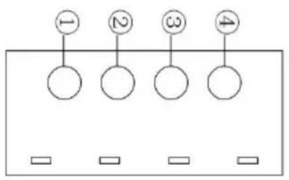
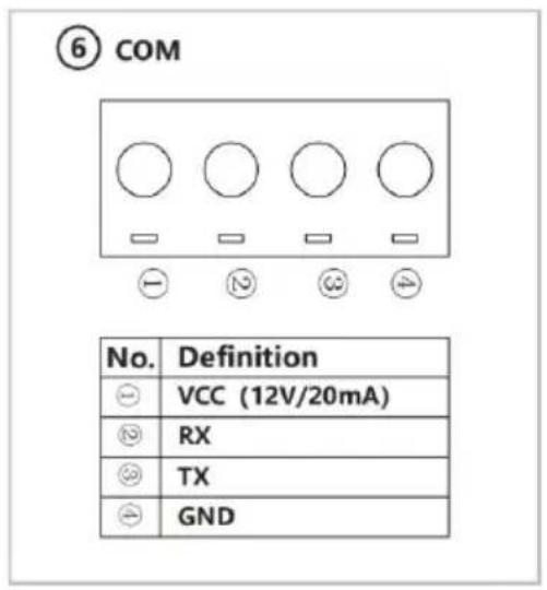
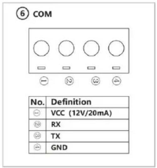
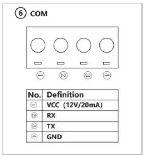
3.3 TTL Communication
Users can utilize external communication equipment (such as Bluetooth BT-2) or communication protocol to perform data monitoring, parameter setting and other operations for the controller via the port.
T he interface is defined as follows:
flowchart
graph TD
    A["1"] --> B[" "]
    C["2"] --> D[" "]
    E["3"] --> F[" "]
    G["4"] --> H[" "]
| No. | Definition |
| 1 | Controller supplies +12.8V outwards. |
| 2 | Data receiving terminal RX of controller |
| 3 | Data sending terminal TX of controller |
| 4 | GND |
3.4 CAN communication
Optional built-in CAN communication function and RV-C protocol.
| S/N | Definition |
| ① | / |
| ② | / |
| ③ | / |
| ④ | GND |
| ⑤ | / |
| ⑥ | / |
| ⑦ | CANH |
| ⑧ | CANL |
4. PRODUCT PROTECTION AND SYSTEM MAINTENANCE
4.1 Protections
Waterproofing protection
Rating: IP32
Input power limited protection
When the power of solar panel is higher than the rated value, the c will limit the power of solar panel within the rated power range to p damage by over current, and the controller will enter the current-limiting charge.
➢ Battery reverse polarity protection
If the battery polarity is reversed, the system will not work but it will burn out the controller.
PV input end voltage is too high
If the voltage at the PV array input end is too high, the controller v automatically shut off the PV input.
▶ PV input end short circuit protection
If the voltage at the PV array input end is short circuited, the control turn off charging; after short circuit is removed, charging will automatic recover.
PV input reverse polarity protection
When the polarity of PV array is reversed, the controller will not be damaged, and normal operation will continue after wiring error is corre
Night reverse charging protection
Prevent battery discharge through the solar panel at night.
▶ TVS lightning protection
➢ Over-temperature protection
When temperature of the controller exceeds the set value, it will reduce charging power or stop charging.
4.2 System Maintenance
- In order to maintain the best long-term performance for controller, it recommended to conduct inspections twice a year.
- Make sure the airflow around the controller is not obstructed and remove any dirt or debris from the heat sink.
- Check if the insulation layers of all exposed wires are damaged due to sun exposure, friction with other objects nearby, dry rot, destruction or insects or rodents, etc. If so, it is necessary to repair or replace wire.
- Verify if indicators are consistent with the device operations. Please note to take corrective actions for any malfunctions or error indica if necessary.
- Check all wiring terminals for corrosion, insulation damage, signs of high temperature or burning/discoloration.
Tighten terminal screws.
- Check for dirt, insects nesting and corrosion and clean as required.
- If the lightning arrester has failed, replace it in time to protect con and other devices of the user from being damaged by lightning.operations. Please note to take corrective actions for any malfunctions or error indications if necessary.

Warning: Danger, electric shock hazards! Make sure that all power
supplies to the controller have been disconnected before check or operation as above.!
5. TECHNICAL PARAMETERS
5.1 Electrical parame ters
| Items | Parameters | |||
| Model | MC2430N10-B | MC2440N10-B | MC2450N10-B | |
| System voltage | 12V/24V | |||
| Zero load loss | <10mA | |||
| Battery voltage | 9V~32V | |||
| Maximum PV open circuit voltage | 92V(25°C); 100V(Lowest ambient temperature) | |||
| Maximum power point voltage range | (Battery voltage +2V) ~ 72V | |||
| Rated charging current | 30A | 40A | 50A | |
| Maximum PV input pov | 400W/12V800W/24V | 550W/12V1100W/24V | 660W/12V1320W/24V | |
| Charging conversion efficiency | ≤98% | |||
| MPPT tracking efficienc | >99% | |||
| Temperature compensation coefficien | -3mv/°C/2V (default); Lithium battery features no temperature compen | |||
| Operating temperature | -35°C to 45°C | |||
| IP rating | IP32 | |||
| Weight | 830g | 1040g | 1335g | |
| Communication mode | TTL Serial communication | |||
| Optional features | Built-in bluetooth and CAN communication | |||
| Altitude | ≤ 3000 meters | |||
| Dimensions (mm) | 150*105.6*67.5 | 183*127*65.5 | 183*127*69.5 | |
| Description:Optional built-in bluetooth communication function, the corresponding product model is MCXX stands for 20/30/40/50.Optional built-in can communication function, the corresponding product model is MC24xxNXX stands for 20/30/40/50. | ||||
5.2. Batt ery type default paramet ers
| Comparison of parameters of various types of battery | |||||
| Set voltageBattery type | Sealed lead-acid battery | Colloidal lead-acid batter | Vented lead-acid battery | Lithium battery | User defined |
| Overvoltage disconnection voltage | 16.0V | 16.0V | 16.0V | — | 9 ~ 17V |
| Equalizing charge voltage | 14.6V | — | 14.8V | — | 9 ~ 17V |
| Boost charge voltage | 14.4V | 14.2V | 14.6V | 14.4V | 9 ~ 17V |
| Floating charge voltage | 13.8V | 13.8V | 13.8V | — | 9 ~ 17V |
| Boost charge recovery voltage | 13.2V | 13.2V | 13.2V | — | 9 ~ 17V |
| Equalizing charge duration | 120 min. | — | 120 min. | — | 0 ~ 600 min. |
| Equalizing charge interval | 30 days | 0 days | 30 days | — | 0 ~ 250D(0 indicates turning equalizing charge function) |
| Boost charge duration | 120 min. | 120 min. | 120 min. | — | 10 ~ 600 min. |
If a user-defined battery is used, the default voltage parameters of the system are the same as those of the sealed lead-acid battery. The fol logic must be followed when you modify battery charge and discharge parameters:
Overvoltage disconnection voltage> charge limit voltage ≥ equalizing charge voltage ≥ boost charge voltage ≥ floating charge voltage> boost charge recovery voltage;
Overvoltage disconnection voltage> Overvoltage disconnection recovery voltage;
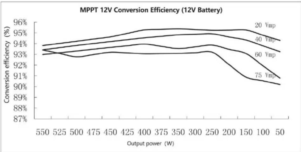
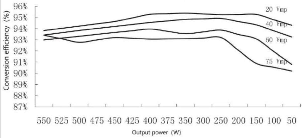
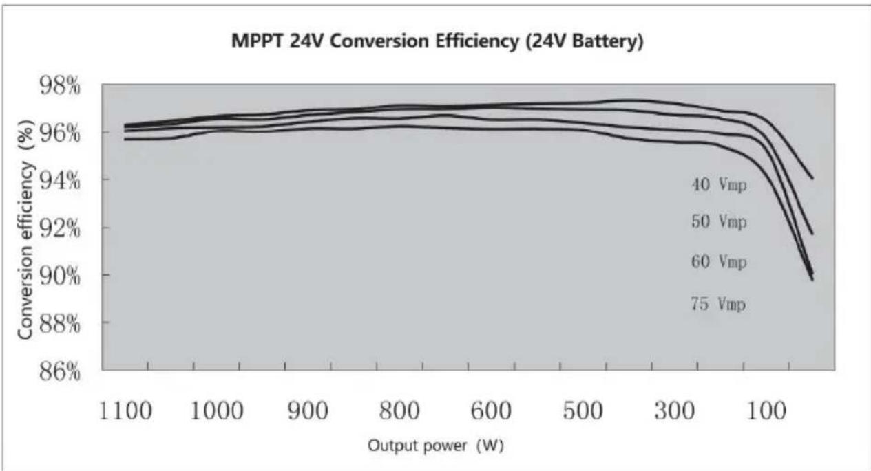
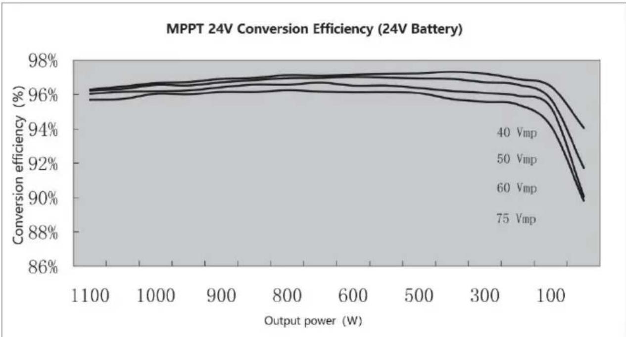
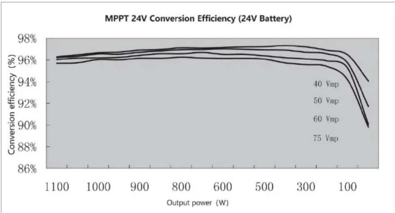
6. CONVERSION EFFICIENCY CURVE
6.1 12V Syste m
line
| Output power (W) | 20 Vmp | 40 Vmp | 60 Vmp | 75 Vmp | | ---------------- | ------ | ------ | ------ | ------ | | 550 | 93.8% | 93.5% | 93.2% | 93.0% | | 525 | 94.0% | 93.7% | 93.4% | 92.8% | | 500 | 94.2% | 93.8% | 93.5% | 92.9% | | 475 | 94.4% | 94.0% | 93.6% | 93.0% | | 450 | 94.6% | 94.2% | 93.7% | 93.1% | | 425 | 94.8% | 94.4% | 93.8% | 93.2% | | 400 | 95.0% | 94.6% | 93.9% | 93.3% | | 375 | 95.1% | 94.7% | 94.0% | 93.4% | | 350 | 95.2% | 94.8% | 94.1% | 93.5% | | 300 | 95.3% | 94.9% | 94.2% | 93.6% | | 250 | 95.4% | 95.0% | 94.3% | 93.7% | | 200 | 95.5% | 95.1% | 94.4% | 93.8% | | 150 | 95.6% | 95.2% | 94.5% | 93.9% | | 100 | 95.7% | 95.3% | 94.6% | 94.0% | | 50 | 95.8% | 95.4% | 94.7% | 94.1% |6.2 24V Syste m

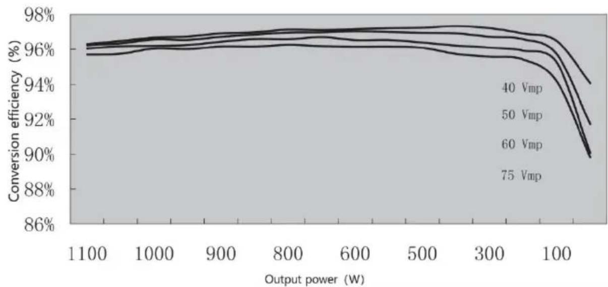
line
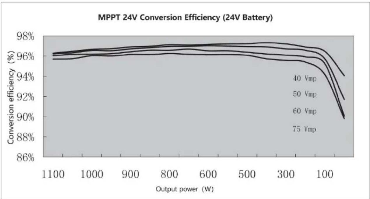
| Output power (W) | 40 Vmp | 50 Vmp | 60 Vmp | 75 Vmp | | ---------------- | ------ | ------ | ------ | ------ | | 1100 | 96% | 96% | 96% | 96% | | 1000 | 96% | 96% | 96% | 96% | | 900 | 96% | 96% | 96% | 96% | | 800 | 96% | 96% | 96% | 96% | | 600 | 96% | 96% | 96% | 96% | | 500 | 96% | 96% | 96% | 96% | | 300 | 96% | 96% | 96% | 96% | | 100 | 94% | 94% | 94% | 94% | | >100 | ~90% | ~89% | ~88% | ~87% |7. PRODUCT DIMENSIONS
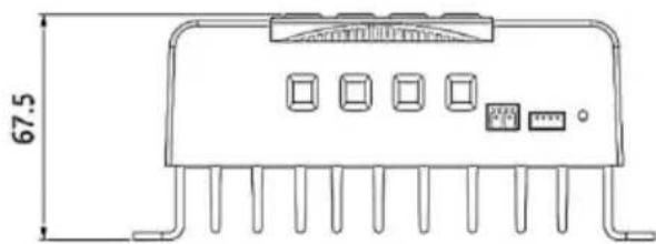
natural_image
Technical line drawing of an electronic component with pins and a 67.5mm dimension label (no text or symbols beyond measurement)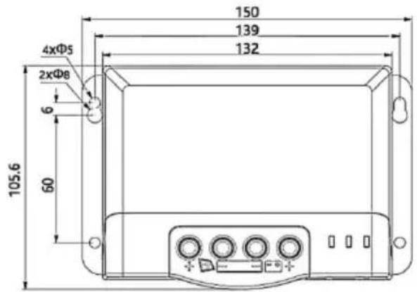
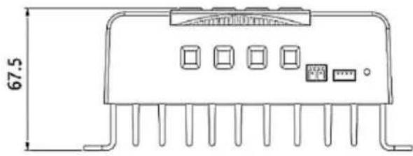
Model: MC2430N10-B;
Outline dimensions: 150*105.6*67.5mm;
Mounting dimensions: 139*60mm;
Fixed holes dia: Φ5mm;
Wire specifications: 20-6AWG.
natural_image
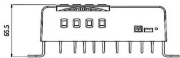
Technical line drawing of an electronic component with pins and a 65.5mm dimension label (no readable text or symbols beyond measurement)
natural_image
Technical line drawing of an electronic component with pins and a 69.5mm dimension label (no readable text or symbols beyond measurement)
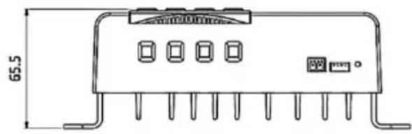
Model: MC2440N10-B;
Outline dimensions: 183*127*65.5mm;
Mounting dimensions: 168*85mm;
Fixed holes dia: Φ5mm;
Wire specifications: 20-6AWG.
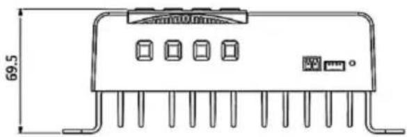
Model: MC2450N10-B;
Outline dimensions: 183*127*69.5mm;
Mounting dimensions: 168*85mm;
Fixed holes dia: Φ5mm;
Wire specifications: 20-6AWG.
8.APP CONTROL FUNCTION
- Please use your mobile phone to scan the QR code in the image

- Follow the prompts to download the APP software and complete the follow-up.
- After the APP installation is completed, please follow the prompts to set up the connection, after the connection is successful, you can query the information of the device and control the device on the mobile phone.
Address: Baoshanqu Shuangchenglu 803long 11hao 1602A-1609shi Shanghai
Imported to AUS: SIHAO PTY LTD, 1 ROKEVA STREETEASTWOOD NSW 2122 Australia
Imported to USA: Sanven Technology Ltd, Suite 250, 9166 Anaheim Place, Rancho Cucamonga, CA 91730
| EC | REP |
SHUNSHUN GmbH
Römeräcker 9 Z2021, 76351
Unit 5 Albert Edward House, The
Pavilions Preston, United Kingdom
Made In China
VEVOR®
TOUGH TOOLS, HALF PRICE
Technical Support and E-Warranty Certificate www.vevor.com/support
VEVOR®
TOUGH TOOLS, HALF PRICE
We continue to be committed to provide you tools with competitive price. "Save Half", "Half Price" or any other similar expressions used by us only represent estimate of savings you might benefit from buying certain tools with us compared top brands and does not necessarily mean to cover all categories of tools offered are kindly reminded to verify carefully when you are placing an order with us actually saving half in comparison with the top major brands.
MODÈLE : MC2430N10-B/ MC2440N10-B/ MC2450N10-B

NEED HELP? CONTACT US!
Have product questions? Need technical support? Please feel fr contact us:
Technical Support and E-Warranty Certificate www.vevor.com/support
This is the original instruction, please read all manual instruction carefully before operating. VEVOR reserves a clear interpretation user manual. The appearance of the product shall be subject to product you received. Please forgive us that we won't inform you there are any technology or software updates on our product.

1.4 MP PT Technology Introductions
bar_line
| U(V) | I(A) | P(W) | VP curve (W) | VI curve (W) | |------|------|------|--------------|--------------| | 0.0 | 5.0 | 0.0 | 0.0 | 0.0 | | 2.8 | 4.9 | 0.5 | 0.5 | 0.5 | | 5.6 | 4.8 | 1.0 | 1.0 | 1.0 | | 8.4 | 4.7 | 1.5 | 1.5 | 1.5 | | 11.2 | 4.6 | 2.0 | 2.0 | 2.0 | | 14.0 | 4.5 | 2.5 | 2.5 | 2.5 | | 16.8 | 4.3 | 3.0 | 3.0 | 3.0 | | 19.6 | 3.5 | 3.5 | 3.5 | 3.5 | | >19.6| <0 | <0 | <0 | <0 |Figure 1-2 Solar panel output characteristics curve
line
| U(V) | I(A) | |------|------| | 0 | High | | 1 | Medium-High | | 2 | Medium | | 3 | Low | | 4 | Low |Figure 1-3 Relationship between solar panel output characteristics and light
line
| Temperature (°C) | Voltage (V) | Current (A) | | ---------------- | ----------- | ----------- | | 20 | ~0 | ~1.0 | | 30 | ~0 | ~0.8 | | 40 | ~0 | ~0.6 | | 50 | ~0 | ~0.4 | | 60 | ~0 | ~0.2 | | 70 | ~0 | ~0.1 |Figure 1-4 Relationship between solar panel output characteristics and temperature
1.5 Charging Stage Introd ucti ons
line
| Time Segment | Battery Voltage (A) | Charge Current (Max.) | | ------------ | ------------------- | --------------------- | | Start | Quick charge | 0 | | Peak | Holding charge | 2h | | End | Floating charge | 3h | | Final | Bulk | 1 |Figure 1-5 Battery charging stages curve graph
a) Charge rapide
Figure 2.1 Installation and Heat Dissipation
natural_image
Line drawing of a rectangular electronic device with mounting flanges and a central control panel (no text or symbols)Étape 4 : le fil

3. PRODUCT OPERATION AND DISPLAY
3.1 LED Indic ator s
3.3 TTL Communication
| No. | Definition |
| 1 | Controller supplies +12.8V outwards. |
| 2 | Data receiving terminal RX of controller |
| 3 | Data sending terminal TX of controller |
| 4 | GND |
3.4 CAN communication
MPPT 12V Conversion Efficiency (12V Battery)
line
| Output power (W) | 20 Vmp | 40 Vmp | 60 Vmp | 75 Vmp | | ---------------- | ------ | ------ | ------ | ------ | | 550 | 93.5% | 93.8% | 93.2% | 93.0% | | 525 | 93.7% | 94.0% | 93.4% | 93.1% | | 500 | 93.8% | 94.2% | 93.5% | 93.2% | | 475 | 94.0% | 94.5% | 93.7% | 93.3% | | 450 | 94.2% | 94.7% | 93.8% | 93.4% | | 425 | 94.5% | 95.0% | 94.0% | 93.5% | | 400 | 94.8% | 95.2% | 94.2% | 93.6% | | 375 | 95.0% | 95.3% | 94.3% | 93.7% | | 350 | 95.1% | 95.4% | 94.4% | 93.8% | | 300 | 95.2% | 95.5% | 94.5% | 93.9% | | 250 | 95.3% | 95.6% | 94.6% | 94.0% | | 200 | 95.4% | 95.7% | 94.7% | 94.1% | | 150 | 95.5% | 95.8% | 94.8% | 94.2% | | 100 | 95.6% | 95.9% | 94.9% | 94.3% | | 50 | 95.7% | 96.0% | 95.0% | 94.4% |6.2 24V Syste m
MPPT 24V Conversion Efficiency (24V Battery)
line
| Output power (W) | 40 Vmp | 50 Vmp | 60 Vmp | 75 Vmp | | ---------------- | ------ | ------ | ------ | ------ | | 1100 | 96% | 96% | 96% | 96% | | 1000 | 96% | 96% | 96% | 96% | | 900 | 96% | 96% | 96% | 96% | | 800 | 96% | 96% | 96% | 96% | | 600 | 96% | 96% | 96% | 96% | | 500 | 96% | 96% | 96% | 96% | | 300 | 96% | 96% | 96% | 96% | | 100 | 94% | 94% | 94% | 94% | | >100 | ~88% | ~88% | ~88% | ~88% |7. PRODUCT DIMENSIONS

natural_image
Technical line drawing of an electronic component with pins and a 67.5mm dimension label (no text or symbols beyond measurement)
Model: MC2430N10-B;
Outline dimensions: 150*105.6*67.5mm;
Mounting dimensions: 139*60mm;
Fixed holes dia: Φ5mm;
Wire specifications: 20-6AWG.

natural_image
Technical line drawing of an electronic component with pins and a 65.5mm dimension label (no text or symbols beyond measurement)
Model: MC2440N10-B;
Outline dimensions: 183*127*65.5mm;
Mounting dimensions: 168*85mm;
Fixed holes dia: Φ5mm;
Wire specifications: 20-6AWG.

natural_image
Technical line drawing of an electronic component with pins and a 69.5mm dimension label (no readable text or symbols beyond measurement)
Model: MC2450N10-B;
Outline dimensions: 183*127*69.5mm;
Mounting dimensions: 168*85mm;
Fixed holes dia: Φ5mm;
Wire specifications: 20-6AWG.
8.APP CONTROL FUNCTION
Unit 5 Albert Edward House, The
Pavilions Preston, United Kingdom
Fabriqué en Chine
VEVOR®
TOUGH TOOLS, HALF PRICE
MC-SERIE MC2430N10-B/ MC2440N10-B/ MC2450N10-B
BEDIENUNGSANLEITUNG
We continue to be committed to provide you tools with competitive price. "Save Half", "Half Price" or any other similar expressions used by us only represent estimate of savings you might benefit from buying certain tools with us compared top brands and does not necessarily mean to cover all categories of tools offered are kindly reminded to verify carefully when you are placing an order with us actually saving half in comparison with the top major brands.
MODELL: MC2430N10-B/ MC2440N10-B/ MC2450N10-B

NEED HELP? CONTACT US!
Have product questions? Need technical support? Please feel fr contact us:
Technical Support and E-Warranty Certificate www.vevor.com/support
This is the original instruction, please read all manual instruction carefully before operating. VEVOR reserves a clear interpretation user manual. The appearance of the product shall be subject to product you received. Please forgive us that we won't inform you there are any technology or software updates on our product.
1.4 MPPT Technology Intro duction s
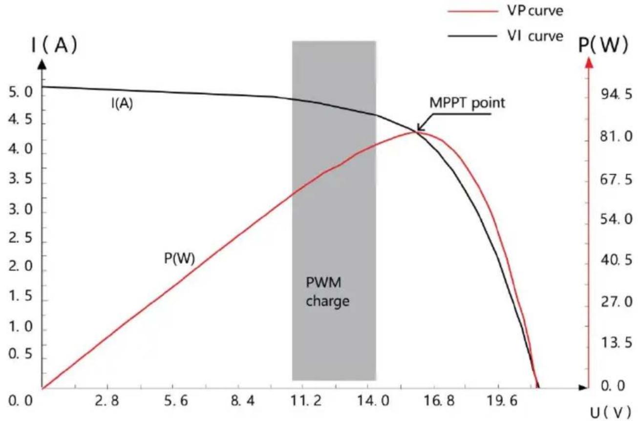
Figure 1-2 Solar panel output characteristics curve
line
| U(V) | I(A) | |------|------| | Low | High | | Medium | Decreasing | | High | Decreasing |Figure 1-3 Relationship between solar panel output characteristics and light

line
| Temperature (°C) | Voltage (V) | Current (A) | | ---------------- | ----------- | ----------- | | 20 | ~0 | ~1.0 | | 30 | ~0 | ~0.9 | | 40 | ~0 | ~0.8 | | 50 | ~0 | ~0.7 | | 60 | ~0 | ~0.6 | | 70 | ~0 | ~0.5 |Figure 1-4 Relationship between solar panel output characteristics and temperature
1.5 Charging Stage Introd ucti ons
line
| Time Segment | Battery Voltage (A) | Charge Current (Max. current) | | ------------ | ------------------- | ----------------------------- | | A | Quick charge | Max. current | | B | Holding charge | - | | C | Floating charge | - | | Bulk | Boost | - | | End | - | - |Figure 1-5 Battery charging stages curve graph
a) Schnellladung
Figure 2.1 Installation and Heat Dissipation
natural_image
Line drawing of a rectangular electronic device with mounting flanges and a central control panel (no text or symbols)Schritt 4: Draht
3. PRODUCT OPERATION AND DISPLAY
3.1 LED Indic ator s
3.3 TTL Communication
| No. | Definition |
| 1 | Controller supplies +12.8V outwards. |
| 2 | Data receiving terminal RX of controller |
| 3 | Data sending terminal TX of controller |
| 4 | GND |
3.4 CAN communication
line
| Output power (W) | 20 Vmp | 40 Vmp | 60 Vmp | 75 Vmp | | ---------------- | ------ | ------ | ------ | ------ | | 550 | 93.8% | 93.5% | 93.2% | 93.0% | | 525 | 94.0% | 93.7% | 93.4% | 92.8% | | 500 | 94.2% | 93.8% | 93.5% | 92.9% | | 475 | 94.4% | 94.0% | 93.6% | 93.0% | | 450 | 94.6% | 94.2% | 93.7% | 93.1% | | 425 | 94.8% | 94.4% | 93.8% | 93.2% | | 400 | 95.0% | 94.6% | 93.9% | 93.3% | | 375 | 95.1% | 94.7% | 94.0% | 93.4% | | 350 | 95.2% | 94.8% | 94.1% | 93.5% | | 300 | 95.3% | 94.9% | 94.2% | 93.6% | | 250 | 95.4% | 95.0% | 94.3% | 93.7% | | 200 | 95.5% | 95.1% | 94.4% | 93.8% | | 150 | 95.6% | 95.2% | 94.5% | 93.9% | | 100 | 95.7% | 95.3% | 94.6% | 94.0% | | 50 | 95.8% | 95.4% | 94.7% | 94.1% |6.2 24V System
line
| Output power (W) | 40 Vmp | 50 Vmp | 60 Vmp | 75 Vmp | | ---------------- | ------ | ------ | ------ | ------ | | 1100 | 96% | 96% | 96% | 96% | | 1000 | 96% | 96% | 96% | 96% | | 900 | 96% | 96% | 96% | 96% | | 800 | 96% | 96% | 96% | 96% | | 600 | 96% | 96% | 96% | 96% | | 500 | 96% | 96% | 96% | 96% | | 300 | 96% | 96% | 96% | 96% | | 100 | 94% | 94% | 94% | 94% | | >100 | ~90% | ~89% | ~88% | ~87% |7. PRODUCT DIMENSIONS

natural_image
Technical line drawing of an electronic component with pins and a 67.5mm dimension label (no text or symbols beyond measurement)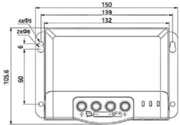
Model: MC2430N10-B;
Outline dimensions: 150*105.6*67.5mm;
Mounting dimensions: 139*60mm;
Fixed holes dia: Φ5mm;
Wire specifications: 20-6AWG.

natural_image
Technical line drawing of an electronic component with pins and a 65.5mm dimension label (no text or symbols beyond measurement)
Model: MC2440N10-B;
Outline dimensions: 183*127*65.5mm;
Mounting dimensions: 168*85mm;
Fixed holes dia: Φ5mm;
Wire specifications: 20-6AWG.

natural_image
Technical line drawing of an electronic component with pins and a 69.5mm dimension label (no readable text or symbols beyond measurement)
Model: MC2450N10-B;
Outline dimensions: 183*127*69.5mm;
Mounting dimensions: 168*85mm;
Fixed holes dia: Φ5mm;
Wire specifications: 20-6AWG.
8.APP CONTROL FUNCTION
Place, Rancho Cucamonga, CA 91730
| EC | REP |
SHUNSHUN GmbH
Römeräcker 9 Z2021, 76351
Unit 5 Albert Edward House, The
Pavilions Preston, United Kingdom
We continue to be committed to provide you tools with competitive price. "Save Half", "Half Price" or any other similar expressions used by us only represent estimate of savings you might benefit from buying certain tools with us compared top brands and does not necessarily mean to cover all categories of tools offered are kindly reminded to verify carefully when you are placing an order with us actually saving half in comparison with the top major brands.
MODELLO: MC2430N10-B/ MC2440N10-B/ MC2450N10-B

NEED HELP? CONTACT US!
Have product questions? Need technical support? Please feel fr contact us:
Technical Support and E-Warranty Certificate www.vevor.com/support
This is the original instruction, please read all manual instruction carefully before operating. VEVOR reserves a clear interpretation user manual. The appearance of the product shall be subject to product you received. Please forgive us that we won't inform you there are any technology or software updates on our product.

1.4 MPPT Technology Intro duction s
bar_line
| U(V) | I(A) | P(W) | VP curve (W) | |------|------|------|--------------| | 0.0 | 5.0 | 0.0 | 0.0 | | 2.8 | 4.9 | 0.5 | 13.5 | | 5.6 | 4.8 | 1.0 | 27.0 | | 8.4 | 4.7 | 1.5 | 40.5 | | 11.2 | 4.6 | 2.0 | 54.0 | | 14.0 | 4.5 | 2.5 | 67.5 | | 16.8 | 4.4 | 3.0 | 81.0 | | 19.6 | 4.3 | 3.5 | 94.5 | | >19.6| 4.2 | 4.0 | ~94.5 |Figure 1-2 Solar panel output characteristics curve
line
| U(V) | I(A) | |------|------| | Low | High | | Medium | Decreasing | | High | Decreasing |Figure 1-3 Relationship between solar panel output characteristics and light
line
| Temperature (°C) | Current (A) | | ---------------- | ----------- | | 20 | ~1.0 | | 30 | ~0.9 | | 40 | ~0.8 | | 50 | ~0.7 | | 60 | ~0.6 | | 70 | ~0.5 |Figure 1-4 Relationship between solar panel output characteristics and temperature
1.5 Charging Stage Introd ucti ons
line
| Time Segment | Battery Voltage (A) | Charge Current (Max. current) | | ------------ | ------------------ | ----------------------------- | | Start | Quick charge | Max. current | | Peak | Holding charge | 2h (Range: 10 to 600min) | | End | Floating charge | 3h (Cumulative time) | | Peak | Bulk | 2h (Range: 10 to 600min) | | End | Boost | 3h (Cumulative time) |Figure 1-5 Battery charging stages curve graph
a) Ricarica rapida
Figure 2.1 Installation and Heat Dissipation
natural_image
Line drawing of a rectangular electronic device with mounting flanges and a central control panel (no text or symbols)Fase 4: filo
3. PRODUCT OPERATION AND DISPLAY
3.1 LED Indic ator s
3.3 TTL Communication
| No. | Definition |
| 1 | Controller supplies +12.8V outwards. |
| 2 | Data receiving terminal RX of controller |
| 3 | Data sending terminal TX of controller |
| 4 | GND |
3.4 CAN communication
line
| Output power (W) | 20 Vmp | 40 Vmp | 60 Vmp | 75 Vmp | | ---------------- | ------ | ------ | ------ | ------ | | 550 | 93.8% | 93.5% | 93.2% | 93.0% | | 525 | 94.0% | 93.7% | 93.4% | 92.8% | | 500 | 94.2% | 93.9% | 93.6% | 92.9% | | 475 | 94.4% | 94.1% | 93.8% | 93.1% | | 450 | 94.6% | 94.3% | 94.0% | 93.3% | | 425 | 94.8% | 94.5% | 94.2% | 93.5% | | 400 | 95.0% | 94.7% | 94.4% | 93.7% | | 375 | 95.1% | 94.8% | 94.5% | 93.8% | | 350 | 95.2% | 94.9% | 94.6% | 93.9% | | 300 | 95.3% | 95.0% | 94.7% | 94.0% | | 250 | 95.4% | 95.1% | 94.8% | 94.1% | | 200 | 95.5% | 95.2% | 94.9% | 94.2% | | 150 | 95.6% | 95.3% | 95.0% | 94.3% | | 100 | 95.7% | 95.4% | 95.1% | 94.4% | | 50 | 95.8% | 95.5% | 95.2% | 94.5% |6.2 24V System

line
| Output power (W) | 40 Vmp | 50 Vmp | 60 Vmp | 75 Vmp | | ---------------- | ------ | ------ | ------ | ------ | | 1100 | 96% | 96% | 96% | 96% | | 1000 | 96% | 96% | 96% | 96% | | 900 | 96% | 96% | 96% | 96% | | 800 | 96% | 96% | 96% | 96% | | 600 | 96% | 96% | 96% | 96% | | 500 | 96% | 96% | 96% | 96% | | 300 | 96% | 96% | 96% | 96% | | 100 | 94% | 94% | 94% | 94% | | >100 | ~90% | ~89% | ~88% | ~87% |7. PRODUCT DIMENSIONS
natural_image
Technical line drawing of an electronic component with pins and a 67.5mm dimension label (no text or symbols beyond measurement)
Model: MC2430N10-B;
Outline dimensions: 150*105.6*67.5mm;
Mounting dimensions: 139*60mm;
Fixed holes dia: Φ5mm;
Wire specifications: 20-6AWG.

natural_image
Technical line drawing of an electronic component with pins and a 65.5mm dimension label (no text or symbols beyond measurement)
Model: MC2440N10-B;
Outline dimensions: 183*127*65.5mm;
Mounting dimensions: 168*85mm;
Fixed holes dia: Φ5mm;
Wire specifications: 20-6AWG.

natural_image
Technical line drawing of an electronic component with pins and a 69.5mm dimension label (no readable text or symbols beyond measurement)
Model: MC2450N10-B;
Outline dimensions: 183*127*69.5mm;
Mounting dimensions: 168*85mm;
Fixed holes dia: Φ5mm;
Wire specifications: 20-6AWG.
8.APP CONTROL FUNCTION
Importato in AUS: SIHAO PTY LTD, 1 ROKEVA STREETEASTWOOD NSW 2122 Australia
Importato negli USA: Sanven Technology Ltd, Suite 250, 9166 Anaheim Place, Rancho Cucamonga, CA 91730
| EC | REP |
SHUNSHUN GmbH
Römeräcker 9 Z2021, 76351
Unit 5 Albert Edward House, The
Pavilions Preston, United Kingdom
Made in China
VEVOR®
TOUGH TOOLS, HALF PRICE
We continue to be committed to provide you tools with competitive price. "Save Half", "Half Price" or any other similar expressions used by us only represent estimate of savings you might benefit from buying certain tools with us compared top brands and does not necessarily mean to cover all categories of tools offered are kindly reminded to verify carefully when you are placing an order with us actually saving half in comparison with the top major brands.
MODELO: MC2430N10-B/ MC2440N10-B/ MC2450N10-B

NEED HELP? CONTACT US!
Have product questions? Need technical support? Please feel fr contact us:
Technical Support and E-Warranty Certificate www.vevor.com/support
This is the original instruction, please read all manual instruction carefully before operating. VEVOR reserves a clear interpretation user manual. The appearance of the product shall be subject to product you received. Please forgive us that we won't inform you there are any technology or software updates on our product.

1.4 MPPT Technology Intro duction s
bar_line
| U(V) | I(A) | P(W) | |------|------|------| | 0.0 | 0.0 | 0.0 | | 2.8 | 1.0 | 13.5 | | 5.6 | 2.0 | 27.0 | | 8.4 | 3.0 | 40.5 | | 11.2 | 4.0 | 54.0 | | 14.0 | 4.5 | 67.5 | | 16.8 | 4.5 | 81.0 | | 19.6 | 0.0 | 94.5 |Figure 1-2 Solar panel output characteristics curve
line
| U(V) | I(A) | |------|------| | Low | High | | Medium | Decreasing | | High | Decreasing |Figure 1-3 Relationship between solar panel output characteristics and light
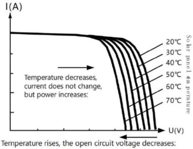
Figure 1-4 Relationship between solar panel output characteristics and temperature
1.5 Charging Stage Introd ucti ons
line
| Time Segment | Battery Voltage (A) | Charge Current (Max. current) | | ------------ | ------------------- | ----------------------------- | | A | Quick charge | Max. current | | B | Holding charge | - | | C | Floating charge | - | | Bulk | Boost | - | | End | - | - |Figure 1-5 Battery charging stages curve graph
a) Carga rápida
Figure 2.1 Installation and Heat Dissipation
natural_image
Line drawing of a rectangular electronic device with mounting flanges and a central control panel (no text or symbols)Paso 4: cablear

3. PRODUCT OPERATION AND DISPLAY
3.1 LED Indic ator s
3.3 TTL Communication
| No. | Definition |
| 1 | Controller supplies +12.8V outwards. |
| 2 | Data receiving terminal RX of controller |
| 3 | Data sending terminal TX of controller |
| 4 | GND |
3.4 CAN communication
MPPT 12V Conversion Efficiency (12V Battery)

line
| Output power (W) | 20 Vmp | 40 Vmp | 60 Vmp | 75 Vmp | | ---------------- | ------ | ------ | ------ | ------ | | 550 | 93.5% | 93.8% | 93.2% | 93.0% | | 525 | 93.7% | 94.0% | 93.4% | 93.1% | | 500 | 93.8% | 94.2% | 93.5% | 93.2% | | 475 | 94.0% | 94.5% | 93.7% | 93.3% | | 450 | 94.2% | 94.7% | 93.8% | 93.4% | | 425 | 94.5% | 95.0% | 94.0% | 93.5% | | 400 | 94.8% | 95.2% | 94.2% | 93.6% | | 375 | 95.0% | 95.3% | 94.3% | 93.7% | | 350 | 95.1% | 95.4% | 94.4% | 93.8% | | 300 | 95.2% | 95.5% | 94.5% | 93.9% | | 250 | 95.3% | 95.6% | 94.6% | 94.0% | | 200 | 95.4% | 95.7% | 94.7% | 94.1% | | 150 | 95.5% | 95.8% | 94.8% | 94.2% | | 100 | 95.6% | 95.9% | 94.9% | 94.3% | | 50 | 95.7% | 96.0% | 95.0% | 94.4% |6.2 24V Syste m
MPPT 24V Conversion Efficiency (24V Battery)

line
| Output power (W) | 40 Vmp | 50 Vmp | 60 Vmp | 75 Vmp | | ---------------- | ------ | ------ | ------ | ------ | | 1100 | 96% | 96% | 96% | 96% | | 1000 | 96% | 96% | 96% | 96% | | 900 | 96% | 96% | 96% | 96% | | 800 | 96% | 96% | 96% | 96% | | 600 | 96% | 96% | 96% | 96% | | 500 | 96% | 96% | 96% | 96% | | 300 | 96% | 96% | 96% | 96% | | 100 | 94% | 94% | 94% | 94% | | >100 | ~90% | ~89% | ~88% | ~87% |7. PRODUCT DIMENSIONS

natural_image
Technical line drawing of an electronic component with pins and a 67.5mm dimension label (no text or symbols beyond measurement)
Model: MC2430N10-B;
Outline dimensions: 150*105.6*67.5mm;
Mounting dimensions: 139*60mm;
Fixed holes dia: Φ5mm;
Wire specifications: 20-6AWG.
natural_image
Technical line drawing of an electronic component with pins and a 65.5mm dimension label (no text or symbols beyond measurement)
Model: MC2440N10-B;
Outline dimensions: 183*127*65.5mm;
Mounting dimensions: 168*85mm;
Fixed holes dia: Φ5mm;
Wire specifications: 20-6AWG.

natural_image
Technical line drawing of an electronic component with pins and a 69.5mm dimension label (no readable text or symbols beyond measurement)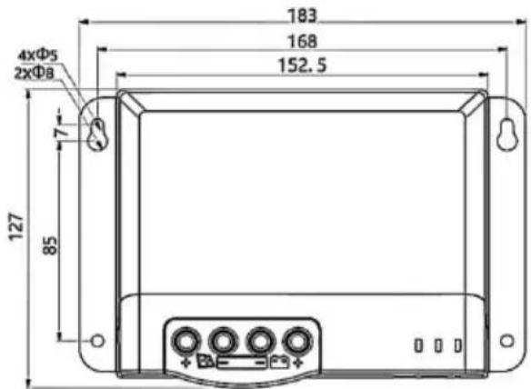
Model: MC2450N10-B;
Outline dimensions: 183*127*69.5mm;
Mounting dimensions: 168*85mm;
Fixed holes dia: Φ5mm;
Wire specifications: 20-6AWG.
8.APP CONTROL FUNCTION
Importado a AUS: SIHAO PTY LTD, 1 ROKEVA STREETEASTWOOD NSW 2122 Australia
Importado a EE. UU.: Sanven Technology Ltd, Suite 250, 9166 Anah Place, Rancho Cucamonga, CA 91730
| EC | REP |
SHUNSHUN GmbH
Römeräcker 9 Z2021, 76351
Unit 5 Albert Edward House, The
Pavilions Preston, United Kingdom
Hecho en china
VEVOR®
TOUGH TOOLS, HALF PRICE
We continue to be committed to provide you tools with competitive price. "Save Half", "Half Price" or any other similar expressions used by us only repeat of savings you might benefit from buying certain tools with us compared top brands and does not necessarily mean to cover all categories of tools offered are kindly reminded to verify carefully when you are placing an order with us actually saving half in comparison with the top major brands.
MODELE: MC2430N10-B/ MC2440N10-B/ MC2450N10-B

NEED HELP? CONTACT US!
Have product questions? Need technical support? Please feel fr contact us:
Technical Support and E-Warranty Certificate www.vevor.com/support
This is the original instruction, please read all manual instruction carefully before operating. VEVOR reserves a clear interpretation user manual. The appearance of the product shall be subject to product you received. Please forgive us that we won't inform you there are any technology or software updates on our product.
1.4 MP PT Technology Introductions
bar_line
| U(V) | I(A) | P(W) | |------|------|------| | 0.0 | 0.0 | 0.0 | | 2.8 | 1.0 | 13.5 | | 5.6 | 2.0 | 27.0 | | 8.4 | 3.0 | 40.5 | | 11.2 | 4.0 | 54.0 | | 14.0 | 4.5 | 67.5 | | 16.8 | 4.5 | 81.0 | | 19.6 | 0.0 | 94.5 |Figure 1-2 Solar panel output characteristics curve
line
| U(V) | I(A) | |------|------| | 0 | High | | 1 | Medium-High | | 2 | Medium | | 3 | Low | | 4 | Low |Figure 1-3 Relationship between solar panel output characteristics and light
line
| Temperature (°C) | Current (A) | | ---------------- | ----------- | | 20 | ~1.0 | | 30 | ~0.9 | | 40 | ~0.8 | | 50 | ~0.7 | | 60 | ~0.6 | | 70 | ~0.5 |Figure 1-4 Relationship between solar panel output characteristics and temperature
1.5 Charging Stage Introd ucti ons
line
| Time Segment | Battery Voltage (A) | Charge Current (Max. current) | |--------------|--------------------|-------------------------------| | Start | Quick charge | Max. current | | Peak | Holding charge | 2h (Range: 10 to 600min) | | End | Floating charge | 3h (Cumulative time: 3h) | | Peak | Bulk | 2h (Range: 10 to 600min) | | End | Boost | 3h (Cumulative time: 3h) |Figure 1-5 Battery charging stages curve graph
Figure 2.1 Installation and Heat Dissipation
natural_image
Line drawing of a rectangular electronic device with mounting flanges and a central control panel (no text or symbols)Krok 4: drut

3. PRODUCT OPERATION AND DISPLAY
3.1 LED Indic ator s
3.3 TTL Communication
| No. | Definition |
| 1 | Controller supplies +12.8V outwards. |
| 2 | Data receiving terminal RX of controller |
| 3 | Data sending terminal TX of controller |
| 4 | GND |
3.4 CAN communication
line
| Output power (W) | 20 Vmp | 40 Vmp | 60 Vmp | 75 Vmp | | ---------------- | ------ | ------ | ------ | ------ | | 550 | 93.8% | 93.5% | 93.2% | 93.0% | | 525 | 94.0% | 93.7% | 93.4% | 92.8% | | 500 | 94.2% | 93.9% | 93.6% | 92.9% | | 475 | 94.4% | 94.1% | 93.8% | 93.1% | | 450 | 94.6% | 94.3% | 94.0% | 93.3% | | 425 | 94.8% | 94.5% | 94.2% | 93.5% | | 400 | 95.0% | 94.7% | 94.4% | 93.7% | | 375 | 95.1% | 94.8% | 94.5% | 93.8% | | 350 | 95.2% | 94.9% | 94.6% | 93.9% | | 300 | 95.3% | 95.0% | 94.7% | 94.0% | | 250 | 95.4% | 95.1% | 94.8% | 94.1% | | 200 | 95.5% | 95.2% | 94.9% | 94.2% | | 150 | 95.6% | 95.3% | 95.0% | 94.3% | | 100 | 95.7% | 95.4% | 95.1% | 94.4% | | 50 | 95.8% | 95.5% | 95.2% | 94.5% |6.2 24V System
line
| Output power (W) | 40 Vmp | 50 Vmp | 60 Vmp | 75 Vmp | | ---------------- | ------ | ------ | ------ | ------ | | 1100 | 96% | 96% | 96% | 96% | | 1000 | 96% | 96% | 96% | 96% | | 900 | 96% | 96% | 96% | 96% | | 800 | 96% | 96% | 96% | 96% | | 600 | 96% | 96% | 96% | 96% | | 500 | 96% | 96% | 96% | 96% | | 300 | 96% | 96% | 96% | 96% | | 100 | 94% | 94% | 94% | 94% | | >100 | ~90% | ~89% | ~88% | ~87% |7. PRODUCT DIMENSIONS

natural_image
Technical line drawing of an electronic component with pins and a 67.5mm dimension label (no text or symbols beyond measurement)
Model: MC2430N10-B;
Outline dimensions: 150*105.6*67.5mm;
Mounting dimensions: 139*60mm;
Fixed holes dia: Φ5mm;
Wire specifications: 20-6AWG.

natural_image
Technical line drawing of an electronic component with pins and a 65.5mm dimension label (no text or symbols beyond measurement)
Model: MC2440N10-B;
Outline dimensions: 183*127*65.5mm;
Mounting dimensions: 168*85mm;
Fixed holes dia: Φ5mm;
Wire specifications: 20-6AWG.

natural_image
Technical line drawing of an electronic component with pins and a 69.5mm dimension label (no readable text or symbols beyond measurement)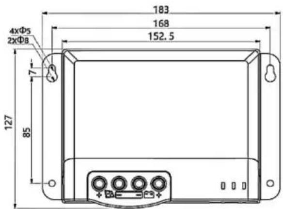
Model: MC2450N10-B;
Outline dimensions: 183*127*69.5mm;
Mounting dimensions: 168*85mm;
Fixed holes dia: Φ5mm;
Wire specifications: 20-6AWG.
8.APP CONTROL FUNCTION
STREETEASTWOOD NSW 2122 Australia
Importowane do USA: Sanven Technology Ltd, Suite 250, 9166 Anar
Place, Rancho Cucamonga, CA 91730
| EC | REP |
SHUNSHUN GmbH
Römeräcker 9 Z2021, 76351
Unit 5 Albert Edward House, The
Pavilions Preston, United Kingdom
We continue to be committed to provide you tools with competitive price. "Save Half", "Half Price" or any other similar expressions used by us only rep estimate of savings you might benefit from buying certain tools with us compared top brands and does not necessarily mean to cover all categories of tools offer are kindly reminded to verify carefully when you are placing an order with us actually saving half in comparison with the top major brands.
MODEL: MC2430N10-B/ MC2440N10-B/ MC2450N10-B

NEED HELP? CONTACT US!
Have product questions? Need technical support? Please feel fr contact us:
Technical Support and E-Warranty Certificate www.vevor.com/support
This is the original instruction, please read all manual instruction carefully before operating. VEVOR reserves a clear interpretation user manual. The appearance of the product shall be subject to product you received. Please forgive us that we won't inform you there are any technology or software updates on our product.

1.4 MPPT Technology Intro duction s
bar_line
| U(V) | I(A) | P(W) | P(W) | |------|------|------|------| | 0.0 | 5.0 | 0.0 | 0.0 | | 2.8 | 4.9 | 0.5 | 0.5 | | 5.6 | 4.8 | 1.0 | 1.0 | | 8.4 | 4.7 | 1.5 | 1.5 | | 11.2 | 4.6 | 2.0 | 2.0 | | 14.0 | 4.5 | 2.5 | 2.5 | | 16.8 | 4.3 | 3.0 | 3.0 | | 19.6 | 3.5 | 3.5 | 3.5 | | >19.6| <0 | <0 | <0 |Figure 1-2 Solar panel output characteristics curve
line
| U(V) | I(A) | |------|------| | Low | High | | Medium | Decreasing | | High | Decreasing |Figure 1-3 Relationship between solar panel output characteristics and light
line
| Temperature (°C) | Voltage (V) | Current (A) | | ---------------- | ----------- | ----------- | | 20 | ~0 | ~1.0 | | 30 | ~0 | ~0.8 | | 40 | ~0 | ~0.6 | | 50 | ~0 | ~0.4 | | 60 | ~0 | ~0.2 | | 70 | ~0 | ~0.1 |Figure 1-4 Relationship between solar panel output characteristics and temperature
1.5 Charging Stage Introd ucti ons
line
| Time Segment | Battery Voltage | Charge Current | | ------------ | --------------- | -------------- | | A | Quick charge | Max. current | | B | Holding charge | 2h | | C | Floating charge | 3h |Figure 1-5 Battery charging stages curve graph
a) Snel opladen
Figure 2.1 Installation and Heat Dissipation
natural_image
Line drawing of a rectangular electronic device with mounting flanges and a central control panel (no text or symbols)Stap 4: draad
3. PRODUCT OPERATION AND DISPLAY
3.1 LED Indic ator s
3.3 TTL Communication
| No. | Definition |
| 1 | Controller supplies +12.8V outwards. |
| 2 | Data receiving terminal RX of controller |
| 3 | Data sending terminal TX of controller |
| 4 | GND |
3.4 CAN communication
line
| Output power (W) | 20 Vmp | 40 Vmp | 60 Vmp | 75 Vmp | | ---------------- | ------ | ------ | ------ | ------ | | 550 | 93.8% | 93.5% | 93.3% | 93.2% | | 525 | 94.0% | 93.7% | 93.4% | 93.1% | | 500 | 94.2% | 93.8% | 93.5% | 93.0% | | 475 | 94.4% | 94.0% | 93.6% | 93.1% | | 450 | 94.6% | 94.2% | 93.7% | 93.2% | | 425 | 94.8% | 94.4% | 93.8% | 93.3% | | 400 | 95.0% | 94.6% | 93.9% | 93.4% | | 375 | 95.1% | 94.7% | 94.0% | 93.5% | | 350 | 95.2% | 94.8% | 94.1% | 93.6% | | 300 | 95.3% | 94.9% | 94.2% | 93.7% | | 250 | 95.4% | 95.0% | 94.3% | 93.8% | | 200 | 95.5% | 95.1% | 94.4% | 93.9% | | 150 | 95.6% | 95.2% | 94.5% | 94.0% | | 100 | 95.7% | 95.3% | 94.6% | 94.1% | | 50 | 95.8% | 95.4% | 94.7% | 94.2% |6.2 24V System
line
| Output power (W) | 40 Vmp | 50 Vmp | 60 Vmp | 75 Vmp | | ---------------- | ------ | ------ | ------ | ------ | | 1100 | 96% | 96% | 96% | 96% | | 1000 | 96% | 96% | 96% | 96% | | 900 | 96% | 96% | 96% | 96% | | 800 | 96% | 96% | 96% | 96% | | 600 | 96% | 96% | 96% | 96% | | 500 | 96% | 96% | 96% | 96% | | 300 | 96% | 96% | 96% | 96% | | 100 | 94% | 94% | 94% | 94% | | >100 | ~88% | ~88% | ~88% | ~88% |7. PRODUCT DIMENSIONS

natural_image
Technical line drawing of an electronic component with pins and a 67.5mm dimension label (no text or symbols beyond measurement)
Model: MC2430N10-B;
Outline dimensions: 150*105.6*67.5mm;
Mounting dimensions: 139*60mm;
Fixed holes dia: Φ5mm;
Wire specifications: 20-6AWG.

natural_image
Technical line drawing of an electronic component with pins and a 65.5mm dimension label (no text or symbols beyond measurement)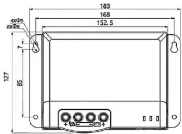
Model: MC2440N10-B;
Outline dimensions: 183*127*65.5mm;
Mounting dimensions: 168*85mm;
Fixed holes dia: Φ5mm;
Wire specifications: 20-6AWG.

natural_image
Technical line drawing of an electronic component with pins and a 69.5mm dimension label (no readable text or symbols beyond measurement)
Model: MC2450N10-B;
Outline dimensions: 183*127*69.5mm;
Mounting dimensions: 168*85mm;
Fixed holes dia: Φ5mm;
Wire specifications: 20-6AWG.
8.APP CONTROL FUNCTION
Anaheim Place, Rancho Cucamonga, CA 91730
| EC | REP |
SHUNSHUN GmbH
Römeräcker 9 Z2021, 76351
Unit 5 Albert Edward House, The
Pavilions Preston, United Kingdom
Gemaakt in China
VEVOR®
TOUGH TOOLS, HALF PRICE
Technisch Ondersteuning en E-garantiecertificaat www.vevor.com/support
VEVOR®
TOUGH TOOLS, HALF PRICE
We continue to be committed to provide you tools with competitive price. "Save Half", "Half Price" or any other similar expressions used by us only represent of savings you might benefit from buying certain tools with us compared top brands and does not necessarily mean to cover all categories of tools offered are kindly reminded to verify carefully when you are placing an order with us actually saving half in comparison with the top major brands.
MODELL: MC2430N10-B/ MC2440N10-B/ MC2450N10-B

NEED HELP? CONTACT US!
Have product questions? Need technical support? Please feel fr contact us:
Technical Support and E-Warranty Certificate www.vevor.com/support
This is the original instruction, please read all manual instruction carefully before operating. VEVOR reserves a clear interpretation user manual. The appearance of the product shall be subject to product you received. Please forgive us that we won't inform you there are any technology or software updates on our product.
1.4 MPPT Technology Intro duction s
bar_line
| U(V) | I(A) | P(W) | |------|------|------| | 0.0 | 0.0 | 0.0 | | 2.8 | 1.0 | 13.5 | | 5.6 | 2.0 | 27.0 | | 8.4 | 3.0 | 40.5 | | 11.2 | 4.0 | 54.0 | | 14.0 | 4.5 | 67.5 | | 16.8 | 4.5 | 81.0 | | 19.6 | 0.0 | 94.5 |Figure 1-2 Solar panel output characteristics curve
line
| U(V) | I(A) | |------|------| | 0 | High | | 1 | Medium-High | | 2 | Medium | | 3 | Low | | 4 | Low |Figure 1-3 Relationship between solar panel output characteristics and light

line
| Temperature (°C) | Current (A) | | ---------------- | ----------- | | 20 | ~1.0 | | 30 | ~0.9 | | 40 | ~0.8 | | 50 | ~0.7 | | 60 | ~0.6 | | 70 | ~0.5 |Figure 1-4 Relationship between solar panel output characteristics and temperature
1.5 Charging Stage Introd ucti ons
line
| Time Segment | Battery Voltage | Charge Current | | ------------ | --------------- | -------------- | | A | Quick charge | Max. current | | B | Holding charge | 2h (Range: 10 to 600min) | | C | Floating charge | 3h (Cumulative) |Figure 1-5 Battery charging stages curve graph
a) Snabbladdning
2.3 Inst all ation and Wiring

Figure 2.1 Installation and Heat Dissipation
natural_image
Line drawing of a rectangular electronic device with mounting flanges and a central control panel (no text or symbols)Steg 4: tråd
3. PRODUCT OPERATION AND DISPLAY
3.1 LED Indic ator s
3.3 TTL Communication
| No. | Definition |
| 1 | Controller supplies +12.8V outwards. |
| 2 | Data receiving terminal RX of controller |
| 3 | Data sending terminal TX of controller |
| 4 | GND |
3.4 CAN communication
Klassificering: IP32
line
| Output power (W) | 20 Vmp | 40 Vmp | 60 Vmp | 75 Vmp | | ---------------- | ------ | ------ | ------ | ------ | | 550 | 93.8% | 93.5% | 93.2% | 93.0% | | 525 | 94.0% | 93.7% | 93.4% | 92.8% | | 500 | 94.2% | 93.8% | 93.5% | 92.9% | | 475 | 94.4% | 94.0% | 93.6% | 93.0% | | 450 | 94.6% | 94.2% | 93.7% | 93.1% | | 425 | 94.8% | 94.4% | 93.8% | 93.2% | | 400 | 95.0% | 94.6% | 93.9% | 93.3% | | 375 | 95.1% | 94.7% | 94.0% | 93.4% | | 350 | 95.2% | 94.8% | 94.1% | 93.5% | | 300 | 95.3% | 94.9% | 94.2% | 93.6% | | 250 | 95.4% | 95.0% | 94.3% | 93.7% | | 200 | 95.5% | 95.1% | 94.4% | 93.8% | | 150 | 95.6% | 95.2% | 94.5% | 93.9% | | 100 | 95.7% | 95.3% | 94.6% | 94.0% | | 50 | 95.8% | 95.4% | 94.7% | 94.1% |6.2 24V Syste m
line
| Output power (W) | 40 Vmp | 50 Vmp | 60 Vmp | 75 Vmp | | ---------------- | ------ | ------ | ------ | ------ | | 1100 | 96% | 96% | 96% | 96% | | 1000 | 96% | 96% | 96% | 96% | | 900 | 96% | 96% | 96% | 96% | | 800 | 96% | 96% | 96% | 96% | | 600 | 96% | 96% | 96% | 96% | | 500 | 96% | 96% | 96% | 96% | | 300 | 96% | 96% | 96% | 96% | | 100 | 94% | 94% | 94% | 94% | | >100 | ~90% | ~88% | ~86% | ~84% |7. PRODUCT DIMENSIONS

natural_image
Technical line drawing of an electronic component with pins and a 67.5mm dimension label (no text or symbols beyond measurement)
Model: MC2430N10-B;
Outline dimensions: 150*105.6*67.5mm;
Mounting dimensions: 139*60mm;
Fixed holes dia: Φ5mm;
Wire specifications: 20-6AWG.

natural_image
Technical line drawing of an electronic component with pins and a 65.5mm dimension label (no text or symbols beyond measurement)
Model: MC2440N10-B;
Outline dimensions: 183*127*65.5mm;
Mounting dimensions: 168*85mm;
Fixed holes dia: Φ5mm;
Wire specifications: 20-6AWG.

natural_image
Technical line drawing of an electronic component with pins and a 69.5mm dimension label (no readable text or symbols beyond measurement)
Model: MC2450N10-B;
Outline dimensions: 183*127*69.5mm;
Mounting dimensions: 168*85mm;
Fixed holes dia: Φ5mm;
Wire specifications: 20-6AWG.
8.APP CONTROL FUNCTION
Unit 5 Albert Edward House, The
Pavilions Preston, United Kingdom
Tillverkad i Kina
VEVOR®
TOUGH TOOLS, HALF PRICE