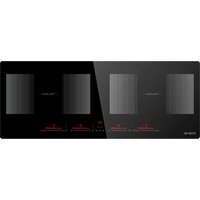
Vittel LNI90DAI1F2Z - Cooker Linarie - Free user manual and instructions
Find the device manual for free Vittel LNI90DAI1F2Z Linarie in PDF.


User questions about Vittel LNI90DAI1F2Z Linarie
0 question about this device. Answer the ones you know or ask your own.
Ask a new question about this device
Download the instructions for your Cooker in PDF format for free! Find your manual Vittel LNI90DAI1F2Z - Linarie and take your electronic device back in hand. On this page are published all the documents necessary for the use of your device. Vittel LNI90DAI1F2Z by Linarie.
USER MANUAL Vittel LNI90DAI1F2Z Linarie
VUE D'ENSEMBLE DES PRODUITS ....4
CONSOMMATION ÉLECTRIQUE ....4
A PROPOS DE LA CUISSON À INDUCTION....6
ACCESSOIRES....7
UTILISATION DE LA TABLE DE CUISSON À INDUCTION 8
UTILISATION DE LA FONCTION BOOST....8
UTILISATION DE LA FONCTION DE MAINTIEN AU CHAUD 9
UTILISATION DE LA FONCTION PAUSE....9
UTILISATION DE LA FONCTION DE VERROUILLAGE DES ENFANTS....9
ZONE FLEXIBLE 11
POUR DÉSACTIVER LA FONCTION SMART FLEX : ......11
UTILISATION DE LA MINUTERIE COMME COMPTE-MINUTES 12
RÉGLAGE DE LA MINUTERIE POUR ÉTEINDRE UNE OU PLUSIEURS ZONES DE CUISSON 12
AFFICHAGE ET INSPECTION DES DÉFAILLANCES 13
UTILISATION DE LA HOTTE ASPIRANTE....14
UTILISATION DE LA FONCTION DE RAPPEL DE CHANGEMENT D'ÉCRAN DU FILTRE 14
UTILISATION DE LA FONCTION D'ARRÊT DIFFÉRÉ....14
UTILISATION DE LA COMBINAISON DU MODE AUTO 15
ENTRETIEN ET MAINTENANCE....16
INSTALLATION 17
AVANT D'INSTALLER LA TABLE DE CUISSON, ASSUREZ-VOUS QUE....20
LORSQUE VOUS AVEZ INSTALLÉ LA TABLE DE CUISSON, ASSUREZ-VOUS QUE ....20
RACCORDEMENT DE LA TABLE DE CUISSON AU RÉSEAU ÉLECTRIQUE....21
MISE AU REBUT DE L'APPAREIL 22
GARANTIE ET SERVICE APRÈS-VENTE 22
text_image
Diagram showing two hand-drawn checkmark and cross symbols on a line, likely indicating correct and incorrect states.text_image
Diagram illustrating cooking process steps with cooking pots, measuring, and heating elements, including dimension annotations.
IMPORTANT: Always lift pans off the cooking surface! Do not slide or drag to avoid damaging the glass. Use a lid that is slightly ajar if using cookware taller than 150mm.
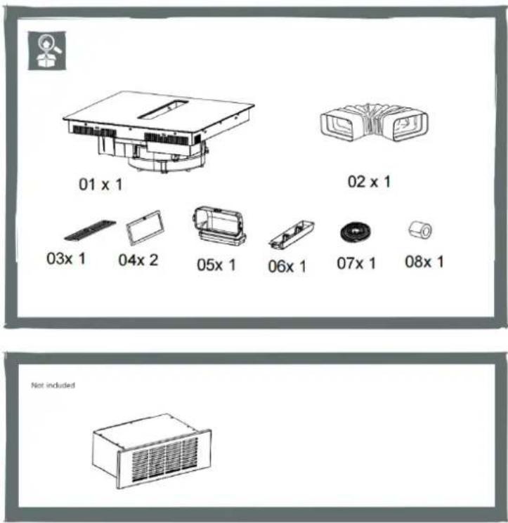
Accessoires
text_image
01 x 1 02 x 1 03x 1 04x 2 05x 1 06x 1 07x 1 08x 1 Not includedtext_image
1 For ducted option. 2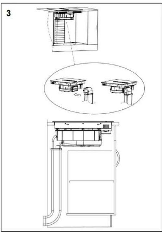
text_image
3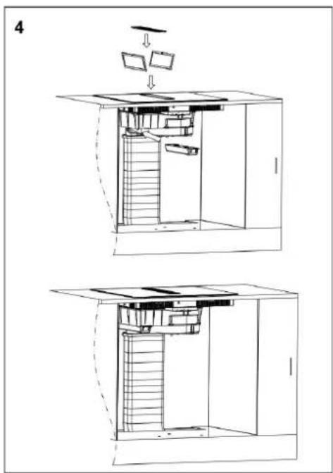
text_image
4natural_image
Technical line drawing of a mechanical assembly inside a container, showing internal components and motion direction (no text or symbols)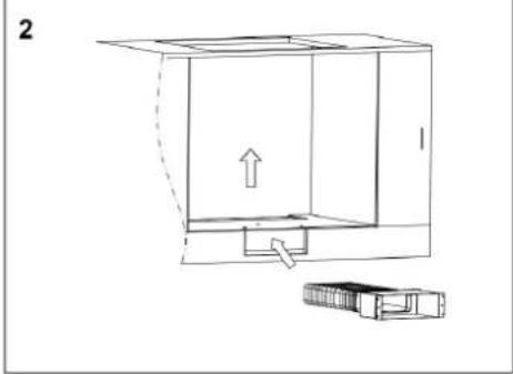
natural_image
Technical line drawing of a mechanical assembly with an arrow indicating direction (no text or symbols)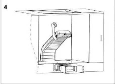
natural_image
Technical line drawing of a mechanical device inside a transparent enclosure, showing internal components and no text or symbols.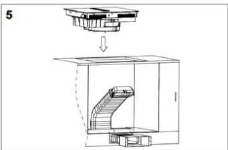
text_image
5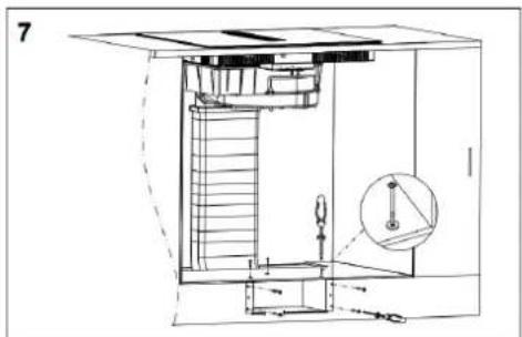
natural_image
Technical line drawing of a mechanical assembly with stairs, gears, and a magnified inset showing a component (no text or symbols)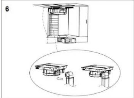
natural_image
Technical line drawing of a multi-level building structure with internal components, shown in two views (top and side), no text or symbols present.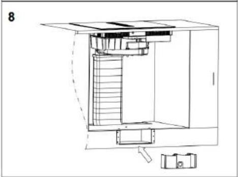
natural_image
Technical line drawing of a mechanical assembly with stairs and components (no text or symbols)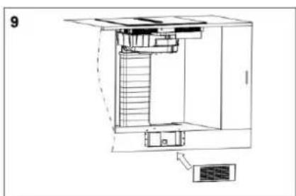
natural_image
Architectural cross-section diagram of a multi-level building with stairs and ventilation unit (no text or labels)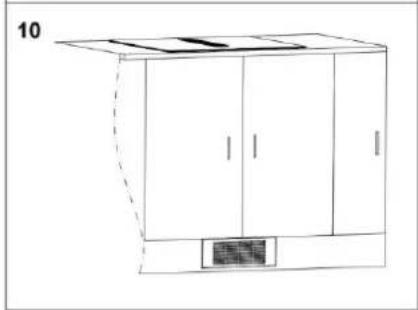
natural_image
Line drawing of a cabinet with doors and a small vent, no text or symbols present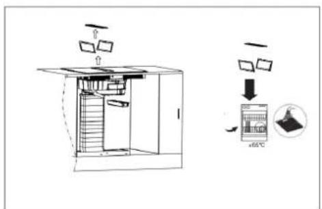
text_image
Diagram illustrating a 3D printing or printing process with labeled components and temperature indication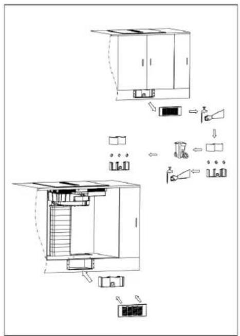
flowchart
graph TD
    A["Storage Tank"] --> B["Refrigerator"]
    B --> C["Airbag"]
    C --> D["Air Bag"]
    D --> E["Recirculator"]
    E --> F["Refrigerator"]
    F --> G["Airbag"]
    G --> H["Recirculator"]
    H --> I["Refrigerator"]
    I --> J["Airbag"]
    J --> K["Recirculator"]
    K --> L["Refrigerator"]
    L --> M["Airbag"]
    M --> N["Recirculator"]
    N --> O["Refrigerator"]
    O --> P["Airbag"]
    P --> Q["Recirculator"]
    Q --> R["Refrigerator"]
    R --> S["Airbag"]
    S --> T["Recirculator"]
    T --> U["Refrigerator"]
    U --> V["Airbag"]
    V --> W["Recirculator"]
natural_image
Architectural cross-section diagrams of a two-story building showing internal structure and ventilation (no text or labels)hello@linarie.com.au
www.linarie.com.au
Follow Us
@Linarie.Appliances

© Linärie
Operating and installation instructions:
Original √ Translation
MKZ SALES
3 IMPASSE DES JARDINIERS
77400 LAGNY SUR MARNE
Linärie Contact
Contact@linarie.fr
www.linarie.fr
The distribution and duplication of this document, as well as the use and disclosure of its contents are prohibited unless expressly authorised.
These operating and installation instructions have been drawn up with the greatest of care. But it cannot be ruled out that subsequent technical modifications have not yet been incorporated or the relevant content has not yet been adapted. Please accept our apologies in this eventuality. An updated version can be requested from our team. Subject to printing errors and mistakes.
© Linärie
All rights reserved.
Vittel
Induction Hob
LIN90DAI1F2Z
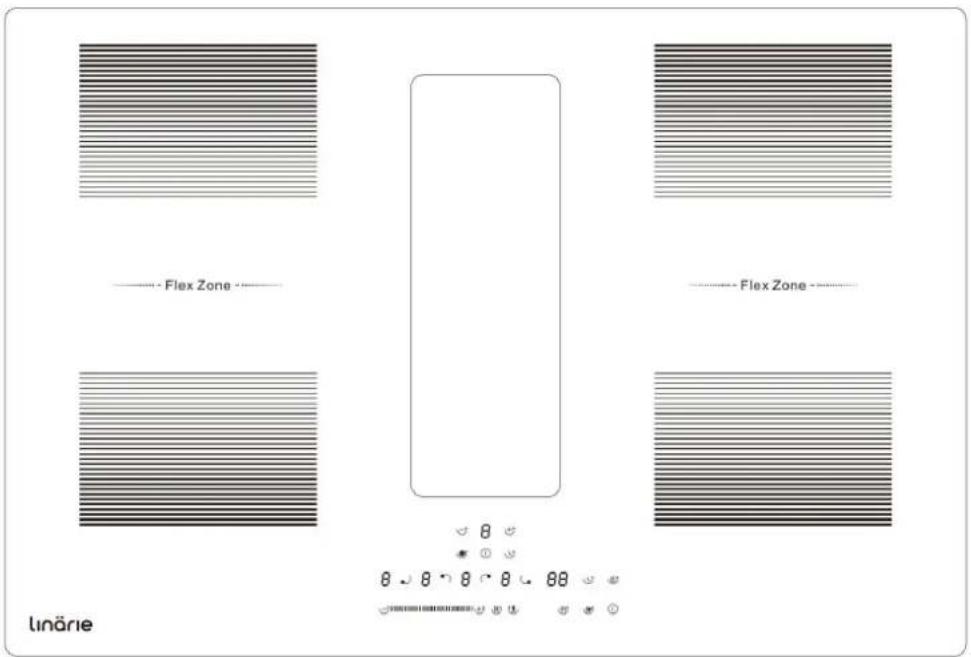
text_image
Flex Zone Flex Zone 8 8 8 8 8 88 linärleCONGRATULATIONS
Congratulations and thank you for choosing Linärie to introduce a new comfort of cooking in your home. We are sure you will find your new appliance a pleasure to use and a great asset to your kitchen.
This appliance complies with all relevant safety requirements in Australia. Inappropriate use can, however, lead to personal injury and damage to property.
In order to operate the unit correctly and safely, please read this instruction manual carefully before installation and usage. This user manual which provides you with all required instructions related to safety, installation, use and maintenance of the appliance.
For future reference, please store this booklet in a safe place and ensure that all users are familiar with the contents. Pass them on to any future owner of the appliance.
Record Model & Serial Number
Model
Serial Number
Register your product www.linarie.com.au

IMPORTANT
Adherence to the directions for use in this manual is extremely important for health and safety. Failure to strictly adhere to the requirements in this manual may result in personal injury and property damage. Products must be used, installed and operated in accordance with this manual. You may not be able to claim on Linărie's manufacturer's warranty in the event that your product fault is due to failure to adhere this manual.
Correct Conditions of Use
- The appliance is intended for use in the home and similar environments only. It is not intended for commercial use.
- The appliance is not suitable for outdoor use, non-stationary installation.
• This product is used for cooking and extracting.

The electricity connection must be made by a qualified specialist. Installation must comply with the valid standards, regulations and laws. All safety and warning information and the operating and installation instructions must be complied with.
Additional information on products, accessories, warranty, replacement parts and services can be found at www.linarie.com.au
TABLE OF CONTENTS
SAFETY WARNINGS....3
PRODUCT OVERVIEW 4
POWER CONSUMPTION 4
ABOUT INDUCTION COOKING....6
ACCESSORIES....7
USING YOUR INDUCTION HOB 8
USING THE BOOST FUNCTION 8
Active boost function....8
Cancel the Boost function....8
USING THE KEEP WARM FUNCTION....9
USING THE PAUSE FUNCTION 9
USING CHILD LOCK FUNCTION 9
Over-Temperature Protection....9
Detection of Small Articles 9
Auto Shutdown Protection....9
FLEXIBLE AREA 10
TO DEACTIVATE THE SMART FLEX FUNCTION: 10
USING THE TIMER AS A MINUTE MINDER 11
SETTING THE TIMER TO TURN ONE OR MORE COOKING ZONES OFF 11
FAILURE DISPLAY AND INSPECTION 12
USING YOUR COOKER HOOD 13
USING THE FILTER SCREEN CHANGE REMINDER FUNCTION ....13
USING THE DELAY SHUTDOWN FUNCTION 13
USING THE AUTO MODE COMBINATION ....14
CARE AND MAINTENANCE 15
INSTALLATION 16
BEFORE YOU INSTALL THE HOB, MAKE SURE THAT 19
WHEN YOU HAVE INSTALLED THE HOB, MAKE SURE THAT....19
CAUTIONS 19
CONNECTING THE HOB TO THE MAINS POWER SUPPLY 20
DISPOSAL OF THE APPLIANCE....21
WARRANTY & AFTER SALES SERVICE....21
Safety Warnings
Your safety is important to us. Please read this information before using your cooktop.
- The appliance is not to be used by persons (including children) with reduced physical, sensory or mental capabilities, or lack of experience and knowledge, unless they have been given supervision or instruction. Children being supervised not to play with the appliance.
- Warning: If the surface is cracked, please switch off the appliance to avoid the possibility of electric shock. The hob surface of glass-ceramic or similar material protects the live parts.
● Warning: A steam cleaner is not be used.
- Metallic objects such as knives, forks, spoons and lids should not be placed on the hob surface since they can get hot when the hob is working.
● After use, switch off the heating element of hob by its control and do not rely on the pan detector.
● The appliance is not intended to be operated by means of external timer or separated remote-control system.
● Danger of fire: Do not store items on the cooking surfaces.
- CAUTION: The cooking process has to be supervised. A short-term cooking process has to be supervised continuously.
● WARNING: Unattended cooking on a hob with fat or oil can be dangerous and may result in a fire.
- If the power cord is damaged, it must be replaced by the manufacturer, its service agent or qualified technical person to avoid any hazard.
- This appliance can be used by children aged from 8 years and above and persons with reduced physical, sensory or mental capabilities or lack of experience and knowledge if they have been given supervision or instruction concerning use of the appliance in a safe way and understand the hazards involved. Children shall not play with the appliance. Cleaning and user maintenance shall not be made by children without supervision.
● WARNING: The appliance and its accessible parts become hot during use.
- Care should be taken to avoid touching heating elements.
● Children less than 8 years of age shall be kept away from the appliance unless continuously supervised.
- NEVER try to extinguish a fire with water, but switch off the appliance and then cover flame e.g. with a lid or a fire blanket.
- WARNING: Use only hob guards designed by the manufacturer of the cooking appliance or indicated by the manufacturer of the appliance in the instructions for use as suitable or hob guards incorporated in the appliance. The use of inappropriate guards can cause accidents.
- Ensure the Power cord isn't accessible after installation.
Product Overview
Top View
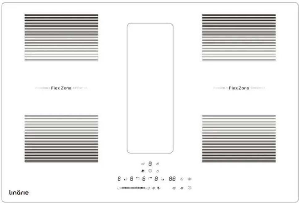
text_image
- Flex Zone - - Flex Zone - linäreUser interface
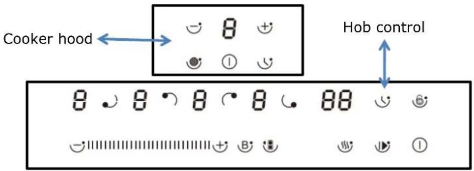
text_image
Cooker hood Hob controlPower consumption
| Heating Zone Max.Power | |
 | 2000/2800W (Booster) |
 | 1500/2000W (Booster) |
| (range hood) | 170W |
 | 2000/2800W (Booster) |
 | 1500/2000W (Booster) |
| Heating Zone Max.Power | |
| Code Reference Description | ||
| A | 8 8 8 8 8 | Zone selects key |
| B Child lock key |  | |
| C |  | ON/OFF key |
| D |  | Boost control key/Keep warm key |
| E |  | Timer key/Pause key for induction hob) |
| H |  | Power/Timer regulating key(reduce) |
| I |  | Power/Timer regulating key(increase) |
| J |  | Keep Warm key |
| K |  | Stop & go key |
| L |  | Flex zone |
| M |  | Filter screen change reminder function key |
| N | [551C] [552T] | Auto mode function button key |
| O | [200C] [4823] | Hood speed adjustment |
About Induction Cooking
Induction cooking is a safe, advanced, efficient, and economical cooking technology. It works by electromagnetic vibrations generating heat directly in the pan, rather than indirectly through heating the glass surface. The glass becomes hot only because the pan eventually warms it up.
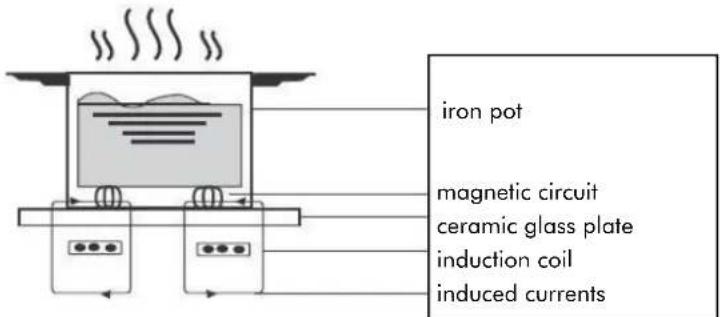
text_image
iron pot magnetic circuit ceramic glass plate induction coil induced currentsBefore using your new induction hob
- Read this guide, taking special note of the 'Safety Warnings' section.
- Remove any protective film that may still be on your Induction hob.
Using the touch controls
- The controls respond to touch, so you don't need to apply any pressure.
- Use the ball of your finger, not its tip.
- You will hear a beep each time a touch is registered.
• Make sure the controls are always clean, dry, and that there is no object (e.g. a utensil or a cloth) covering them. Even a thin film of water may make the controls difficult to operate.
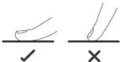
text_image
Diagram showing two hand positions with checkmark and cross symbols, likely illustrating correct and incorrect hand positioning.Choosing the right cookware

- Only use cookware with a base suitable for induction cooking. Look for the induction symbol on the packaging or on the bottom of the pan.
- You can check whether your cookware is suitable by carrying out a magnet test. Move a magnet towards the base of the pan. If it is attracted, the pan is suitable for induction.
- If you do not have a magnet:
- Put some water in the pan you want to check.
- If does not flash in the display and the water is heating, the pan is suitable.
● Cookware made from the following materials is not suitable: pure stainless steel, aluminum or copper without a magnetic base, glass, wood, porcelain, ceramic, and earthenware.
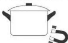
Do not use cookware with jagged edges or a curved base.
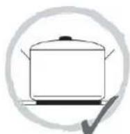
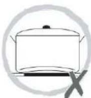
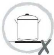
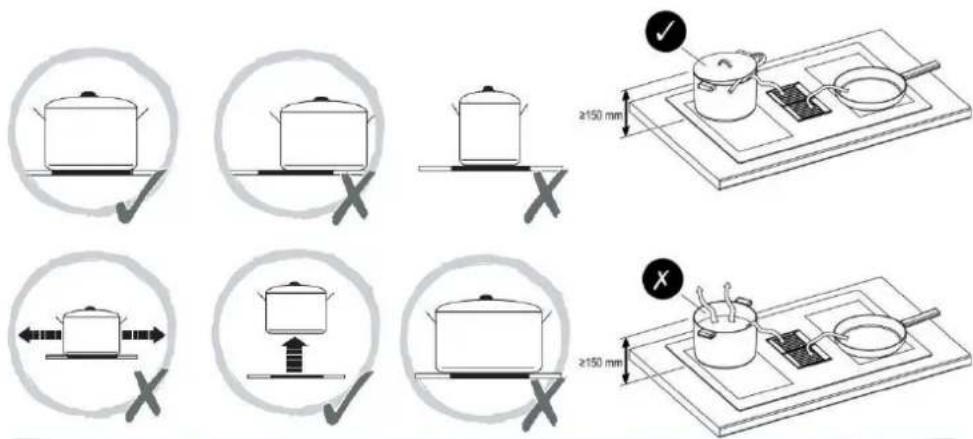
Make sure that the base of your pan is smooth, sits flat against the glass, and is the same size as the cooking zone. Use pans whose diameter is as large as the graphic of the zone selected. Using a pot a slightly wider energy will be used at its maximum efficiency. If you use smaller pot efficiency could be less than expected. Pot less than 140 mm could be undetected by the hob. Always center your pan on the cooking zone.
text_image
Diagram illustrating cooking process steps with pots, pan, and stove placement, showing correct/incorrect actions and distance measurements.
IMPORTANT: Always lift pans off the cooking surface! Do not slide or drag to avoid damaging the glass. Use a lid that is slightly ajar if using cookware taller than 150mm.
Accessories
text_image
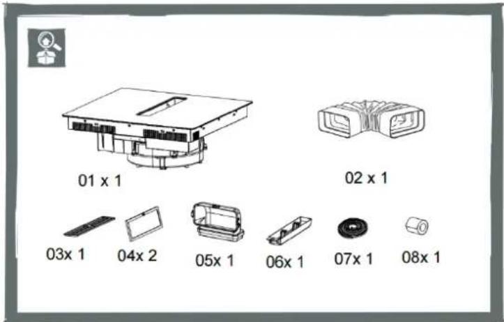
01 x 1 02 x 1 03x 1 04x 2 05x 1 06x 1 07x 1 08x 1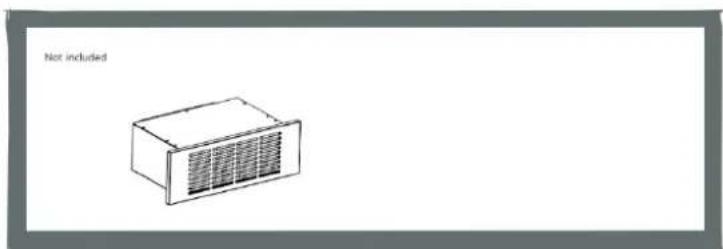
natural_image
Simple line drawing of a rectangular device with ventilation grilles, labeled 'Not included' (text is minimal and not visually present)Using your induction hob
To start cooking
-
Touch the ON/OFF ① key (C) for 3 seconds. After power on, the buzzer beeps once, all displays show “-”, indicating that the induction hob has entered the state of standby mode.
-
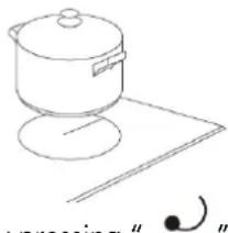
Place a suitable pan on the cooking zone that you wish to use.
- Make sure the bottom of the pan and the surface of the cooking zone are clean and dry.
natural_image
Simple line drawing of a cooking pot on a stand (no text or symbols)-
According to the heating zone where the pan is placed, select a relevant zone select key by pressing " 5" key. The symbol 0. selected will stay fully it.
-
Adjust heat setting by touching the slider regulating key(I) control.
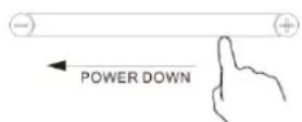
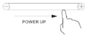
- If you don't choose a heat setting within 1 minute, the induction hob will automatically switch off. You will need to start again at step 1. - You can modify the heat setting at any time during cooking.
If the display flashes ≥slant U ≤slant alternately with the power setting
This means that:
- You have not placed a pan on the correct cooking zone or,
- The pan you're using is not suitable for induction cooking or,
- The pan is too small or not properly centered on the cooking zone.
No heating takes place unless there is a suitable pan on the cooking zone.
The display will automatically turn off after 1 minutes if no suitable pan placed on it or no any other operation.
When you have finished cooking
-
Touching the relevant zone select key(A) that you want to switch off.
-
Press the key (I) ⊖ to decrease the power to "0" level, and the heating will stop.
-
Beware of hot surfaces indicator light "H" will show which cooking zone is hot to touch. It will disappear when the surface has cooled down to a safe temperature. It can also be used as an energy saving function if you want to heat further pans, use the hotplate that is still hot.
Using the Boost function
Active boost function
-
Select the heating zone by touching the zone select key (A)
-
Touching the boost control key (D) Ⓑ, the zone indicator show "P" and the power reach Max.
Cancel the Boost function
-
Touching the relevant zone select key(A) that you want to cancel.
-
Touching the key(I) ⊖ to cancel the Boost function, then the cooking zone will revert to level 9.
- The function can work in any cooking zone.
- The cooking zone returns to level 9 after 5 minutes.
Using the Keep warm Function
You can choose 3 handy cooking functions by pressing the cooking functions key (J) each time moves from one function to the other.
- Melt or defrost (about 50°C)
- Heating or keeping warm (about 70°C)
- Simmering, temperature close to boiling, useful for slow cooking
Using the Pause Function
The hob has a handy restart function to pause and restart the cooking process if you're interrupted.
-
When the hob is on and working, press the pause key (K) all burner will stop working, and all LED indicator will show the symbol " " .
-
Press the pause key, all setting will restart at the previous setting.
Using Child Lock Function
- You can lock the controls to prevent unintended use (for example children accidentally turning the cooking zones on).
- When the controls are locked, all the controls except the OFF control are disabled.
To lock the controls
Touch the key lock control for 3 seconds. The timer indicator will show "Lo"
To unlock the controls
- Make sure the Induction hob is turned on.
- Touch and hold the key lock control for 3 seconds.
- You can now start using your Induction hob.

When the hob is in the lock mode, all the controls are disable except OFF, you can always turn the hob off with OFF control in an emergency, but you shall unlock the hob first in the next operation.
Over-Temperature Protection
A temperature sensor equipped can monitor the temperature inside the Induction hob. When an excessive temperature is monitored, the Induction hob will stop operation automatically.
Detection of Small Articles
When an unsuitable size or non-magnetic pan (e.g. aluminum), or some other small item (e.g. knife, fork, key) has been left on the hob, the hob automatically goes on to standby in 1 minute. The fan will keep cooling down the induction hob for a further 1 minute.
Auto Shutdown Protection
Auto shut down is a safety protection function for your induction hob. It shut down automatically if ever you forget to turn off you're cooking. The default working times for various power levels are shown in the below table:.
| Power level | 1 | 2 | 3 | 4 | 5 | 6 | 7 | 8 | 9 |
| Default working timer (min) | 360 | 360 | 360 | 180 | 180 | 180 | 120 | 120 | 90 |
When the pot is removed, the induction hob can stop heating immediately and the hob automatically switch off after 2 minutes.
People with a heart pace maker should consult with their doctor before using this unit.

FLEXIBLE AREA
- This area can be used as a single zone, accordingly to the cooking needs anytime.
- Flexible area is made of two independent inductors that can be controlled separately. When working as a single zone, a cookware is moved from one zone to the other one within the flexible area keeping the same power level of the zone where the cookware originally was placed, and the part that is not covered by cookware is automatically switched off.
- Important: Make sure to place the cookware centered on the single cooking zone. The ideal recipe is an oval or rectangular saucepan, or a saucepan. Examples of good pot placement and bad pot placement.
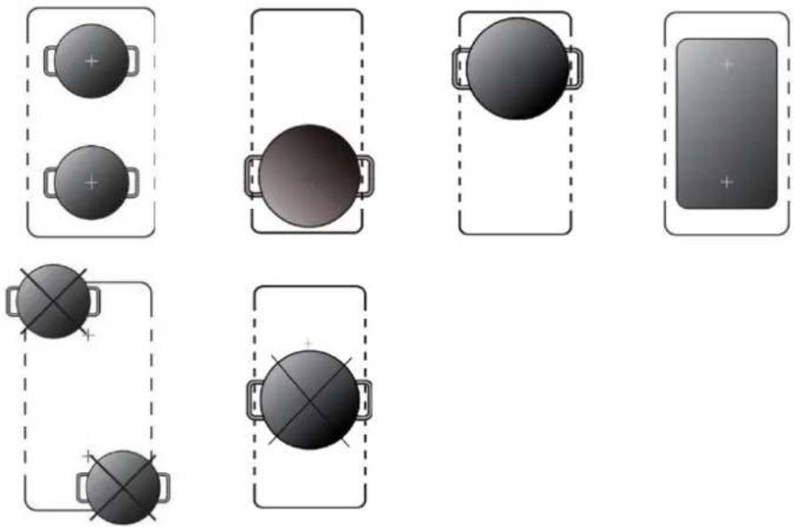
To deactivate the smart flex function:
Enter the mode:
Press the bridge-heating button (L) enter the bridge-heating mode, the display mode as below:
Exit mode:
Press and hold the bridge-heating button for three seconds to exit the bridge mode “ 🔒”, and all the heating zones will be reset to zero at the same time.
- If the pot is moved from the front to the rear part (or vice versa), the flexible area detects automatically the new position, keeping the same power
Using the Timer as a Minute Minder
If you are not selecting any cooking zone
- Make sure at least one cooking is turned on.
Note: you can use the minute minder even if you're not selecting any cooking zone.
- Touch the Timer key(F) ⚙ . The minder indicator will start flashing and "30" will show in the timer display.
- Set the time by touching the "- "or" +" control of the timer
Hint: Touch the “-” or “+” control of the timer once to decrease or increase by 1 minute.
Touch and hold the “-” or “+” control of the timer to decrease or increase by 10 minutes.
Touching the “-” and “+” together, the timer is cancelled, and the timer indicator will turn off.
- When the time is set, it will begin to count down immediately. The display will show the remaining time.
- Buzzer will blip for 30 seconds and the timer indicator will turn off when the setting time finished.
Setting the timer to turn one or more cooking zones off
If the timer is set on one zone:
- Select the relevant cooking zone which is working by touching the zone select key (A).
- Press the Timer key(F) 🤨, the timing indicator flashes, and you can set the timer at this point.
- Using the "+" and "-" buttons, you can realize the setting of timing from 1 to 99 minutes.
Hint: Touch the “-” or “+” control of the timer once will decrease or increase by 1 minute.
Touch and hold the" - "or "+" control of the timer will decrease or increase by 10 minutes.
Touching the" - "and "+" together, the timer is cancelled, and the timer indicator will turn off.
- When the time is set, it will begin to count down immediately. The display will show the remaining time and the timer indicator flash for 5 seconds.
NOTE: The red dot next to power level indicator will illuminate indicating that zone is selected.
6
- When cooking timer expires, the corresponding cooking zone will be switch off automatically. Other cooking zone will keep operating if they are turned on previously.
- when using "the timer as an alarm" and "the timer to switch off the zones" together, the display will show the remaining time of alarm as first priority. Press cooking zone to show the remaining time of switch off timer.
Failure Display and Inspection
If an abnormality comes up, the induction hob will enter the protective state automatically and display corresponding protective codes:
| Error Message | Possible Cause What to do | |
| U | No pot or pot not suitable; Replace the pot; | |
| ER03 | Water or pot on the glass over the control | Clean the user interface |
| The connection between the display board and the left mainboard is fail F1 (the cooking zone which indicator showing “E”) | 1.Connection cable not correctly plugged or defective;2.Replace the Mainboard. | |
| F3E | Coil temperature sensor failure. (the cooking zone which indicator showing “E”) | Replace the coil sensor |
| F4E | Mainboard temperature sensor failure. (the cooking zone which indicator showing “E”) | Replace the mainboard |
| E1E | Temperature sensor of the ceramic glass plate is high | Please restart after the induction hob cools down. |
| E2 E | Temperature sensor of the IGBT is high | Please restart after the induction hob cools down. |
| E3 E | Abnormal supply voltage (too high) | Please inspect whether power supply is normal;Power on after the power supply is normal. |
| E4 E | Abnormal supply voltage (too low) | Please inspect whether power supply is normal;Power on after the power supply is normal. |
| E5 E | Temperature sensor failure (the cooking zone which indicator showing “E”) | Connection cable not correctly plugged or assemble defective; |
The above are the judgment and inspection of common failures.
Please do not disassemble the unit by yourself to avoid any dangers and damages to the induction hob and please contact the service department.
Using your Cooker Hood
flowchart
graph TD
    A["A"] --> B["●"]
    A --> C["⊕"]
    D["○"] --> E["○"]
    F["○"] --> G["○"]
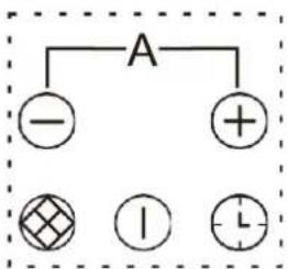
- Touch the ON/OFF key (C) for 3 seconds. After power on, the buzzer beeps once, all displays show “-”, indicating that the cooker hood has entered the state of standby mode.
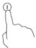
- Select the power level by pressing the "+" key or "-" key
- The power level will start at 0. Pressing the "+" key will count up the power levels from 0.1.2.3.4.5 to P in numerical order.
- If you don't choose a heat setting within 1 minute, the cooker hood will automatically switch off. You will need to start again at step 1.
- You can modify the setting at any time during cooking.
Using the Filter screen change reminder function
At the end of each running cycle, the control panel chip should record the running time and accumulate it.
When the range hood cumulative working hours working time of the more than 50 hours of motor, Filter screen change reminder function is activated, the digital tube
display "two horizontal" I such as machine still continue to work, the "two
horizontal" - alternating with gear), the lights light up and start flashing red continuously, until the user presses the Filter screen change reminder function
key(M) 🔍, the screen to remind the digital tube stop show "two horizontal" = and return to normal, according to the gear mesh remind button close touch control function at the same time, the control board chip cumulative timing to zero, and to the cumulative effect in the next start timing.
Using the Delay shutdown function
- When the fan motor is on and the Delay shutdown function button key(N) flash and the display will show the current fan speed, the delay shutdown function indicator lights up.

is pressed the icon will
-
The chosen speed level will remain in use for five minutes before dropping down to the next lowest speed. This speed will remain in operation for two minutes before dropping down again. This will be repeated every two minutes unless the speed is already at level 1 and then the fan will turn off.
-
Press the Delay shutdown function button key(N) and hold for 3 seconds, it will cancel Delay shutdown function.
- In the process of turning on the delayed shutdown mode and running, if the gear is adjusted by operating the key (O) ⊕ or key(F) ⊖, the above delay shutdown process will be reperformed at the final adjustment gear.
Using the Auto mode
- The AUTO mode can only be entered when both the induction cooker and the hood are running simultaneously.
- Touch and hold the key (O) ⊖ A ⊕ for 3 seconds at the same time.
- After 3 seconds, the digital tube of the range hood displays "A" and flashes for 5 seconds. 5 seconds later, the digital tube of the range hood stops flashing. At this point, the cooker hood enters the automatic mode and the working level of the cooker hood will be adjusted automatically according to the on state of the induction cooker. In auto mode, the digital tube keeps displaying "A" and no longer displays the rest of the gears.
| Speed level of hood | Power level of Hob |
| Speed 1 This speed | will be selected when there are no more than two cooking zones in use, and the combined output is 5 or less. For example, zone 1 is on 1, and zone 2 is on 3. |
| Speed 2 | This speed will be selected when there are no more than three cooking zones in use, and the combined output is between 6 and 10. For example, zone 1 is on 3,zone 2 is on 4 and zone 3 is 3. |
| Speed 3 | This speed will be selected when there are no more than four cooking zones in use, and the combined output is between 11 and 15. For example, zone 1 is on 3, zone 2 is on 4 ,zone 3 is on 5 and zone 4 is on 3. |
| Speed 4 | This speed will be selected when there are between two and four cooking zones in use, and the combined output is between 16 and 21. For example, zone 1 is on 5, zone 2 is on 5 ,zone 3 is on 5 and zone 4 is on 6. |
| Speed 5 This speed | will be selected when there are between three and four cooking zones in use, and the combined output is between 22 and 27. For example, zone 1 is on 5, zone 2 is on 5 ,zone 3 is on 7 and zone 4 is on Boost (10). |
| Speed P - Boost This speed | will be selected when all four cooking zones are in use, and the combined output is greater than 28. For example, zone 1 is on 9, zone 2 is on 9, zone 3 is on 9 and zone 4 is on Boost (10). |
Exit automatic mode
If the range hood runs continuously for 6 hours without receiving any command from the user, it will automatically shut down and enter standby mode.
Failure Display and Inspection
If an abnormality comes up, the range hood will enter the protective state automatically and display corresponding protective codes:
L1: Startup failed----Please inspect whether Motor is normal; Power on after the Motor is normal.
L2: Power line phase loss----Please check if the motor connection is normal; Power on the motor after it is connected normally.
L3: Current too high----Please inspect whether Motor PCB is normal; Power on after the Motor PCB is normal.
L4: Motor temperature is too high----Please check if the motor is running normally; After checking, turn on the power.
L5: Abnormal supply voltage (too high)----Please inspect whether power supply is normal; Power on after the power supply is normal.
L6: Abnormal supply voltage (too low)----Please inspect whether power supply is normal; Power on after the power supply is normal.
Care and maintenance

Warning
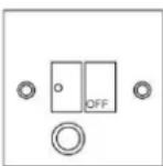
Always switch off the electricity supply before performing maintenance work. In the event of a fault, contact customer services.

Damaged power cables should be replaced by a competent person or qualified electrician.

For domestic use only.

Never place an empty pan on the hob as this will cause an error message to appear on the control panel.

When a cooking zone has been on for a long time, the surface remains hot for some times afterwards so do not touch the ceramic surface.

For sealed foods, please do not heat them before opening removing the lid so as to avoid any dangers of explosion due to heating expansion.

If the surface of the hob is cracked, disconnect from power supply to avoid any possibility of electric shocks.

Do not place rough or uneven pans on the hob, as they could damage the ceramic surface.

Avoid banging pots and pans down on the hob. The ceramic surface is tough but not unbreakable.

Do not put detergents or flammable materials beneath the hob.
Installation
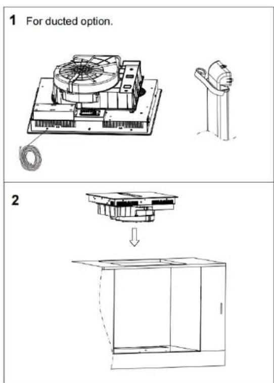
Selection of installation equipment
Section A Without recycle kit
text_image
1 For ducted option. 2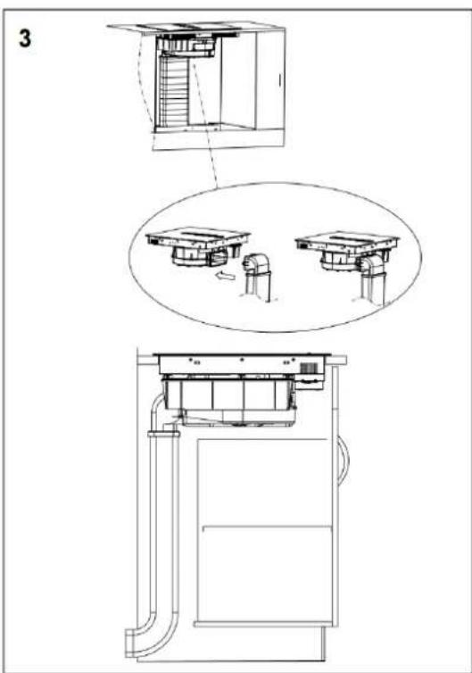
text_image
3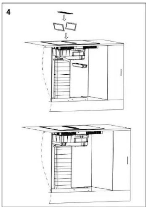
text_image
4Section A With recycle kit
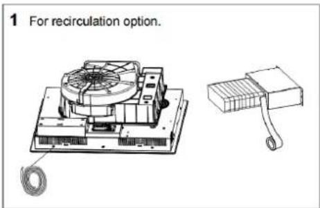
text_image
1 For recirculation option.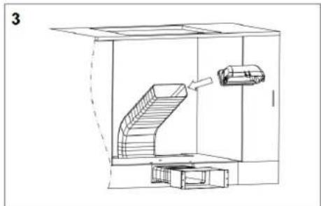
natural_image
Technical line drawing of a mechanical assembly inside a container, showing internal components and motion direction (no text or symbols)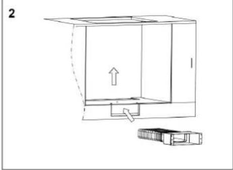
natural_image
Technical line drawing of a mechanical assembly with an arrow indicating direction (no text or symbols)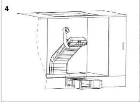
natural_image
Technical line drawing of a mechanical device inside a transparent enclosure, showing internal components and no text or symbols.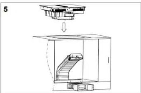
text_image
5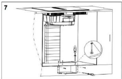
natural_image
Technical line drawing of a mechanical assembly with stairs, gears, and a magnified inset showing a component (no text or symbols)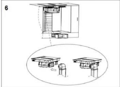
natural_image
Technical line drawing of a multi-level building structure with internal components, shown in two views (top and side), no text or symbols present.
natural_image
Technical line drawing of a mechanical assembly with stairs and components (no text or symbols)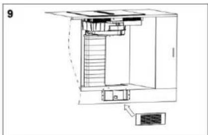
natural_image
Architectural line drawing of a multi-level building interior with stairs and ventilation unit (no text or symbols)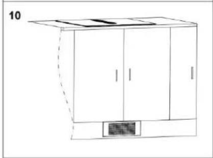
natural_image
Line drawing of a cabinet with doors and a small vent, no text or symbols present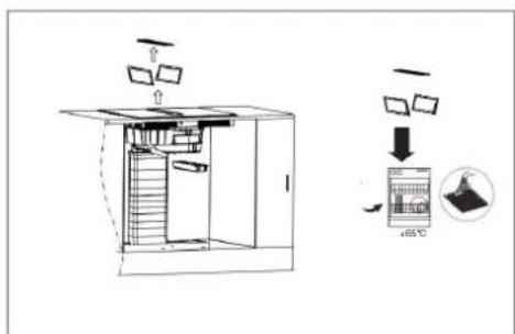
text_image
Diagram illustrating a refrigeration or cooling system with labeled components and temperature measurement
text_image
Technical diagram showing exploded view of a multi-level appliance assembly with labeled components and directional arrows indicating process flow.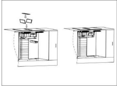
natural_image
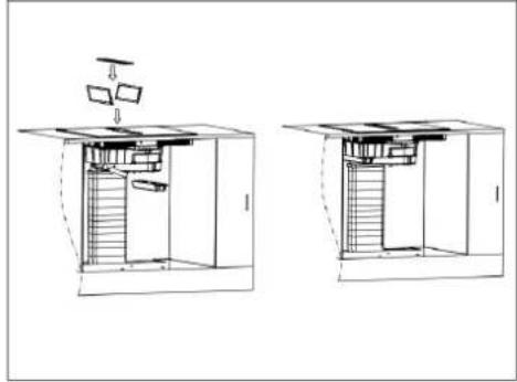
Architectural cross-section diagrams of a two-story building showing internal structure and ventilation (no text or labels)Choose a type of installation:
Ducted option A (extraction to the outside) or Recirculation option B (no extraction to the outside).

The above pipeline accessories are optional, please consult relevant sales channels for details.
Caution! Before drilling it is extremely important to check the wall for hidden pipes, electrical cables etc. using an appropriate detection device.
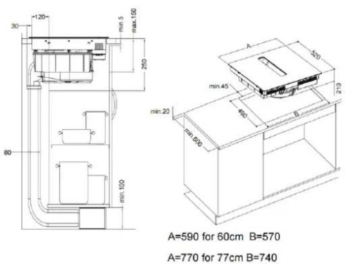
Cut out the work surface according to the sizes shown in the drawing.
For the purpose of installation and use, a minimum of 5 cm space shall be preserved around the hole.
Be sure the thickness of the work surface is at least 30 mm. Please select
heat-resistant work surface material to avoid larger deformation caused by the heat radiation from the hotplate. As shown below:
text_image
30 -120 min.5 max.150 250 80 min.100 A=590 for 60cm B=570 A=770 for 77cm B=740 min.20 min.45 400 B min.600 520 210Before you install the hob, make sure that
• The work surface is square and level, and no structural members interfere with space requirements
• The work surface is made of a heat-resistant material
- If the hob is installed above an oven, the oven has a built-in cooling fan
• The installation will comply with all clearance requirements and applicable standards and regulations
- A suitable isolating switch providing full disconnection from the mains power supply is incorporated in the permanent wiring, mounted and positioned to comply with the local wiring rules and regulations.
The isolating switch must be of an approved type and provide a 3 mm air gap contact separation in all poles (or in all active [phase] conductors if the local wiring rules allow for this variation of the requirements)
• The isolating switch will be easily accessible to the customer with the hob installed
• You consult local building authorities and by-laws if in doubt regarding installation
- You use heat-resistant and easy-to-clean finishes (such as ceramic tiles) for the wall surfaces surrounding the hob.
When you have installed the hob, make sure that
- The power supply cable is not accessible through cupboard doors or drawers
• There is adequate flow of fresh air from outside the cabinetry to the base of the hob - If the hob is installed above a drawer or cupboard space, a thermal protection barrier is installed below the base of the hob to avoid touching the bottom of the hob.
- The isolating switch is easily accessible by the customer
Cautions
This appliance must be installed by the qualified technical person in compliance with the instructions provided. The manufacturer declines all responsibility for improper installation, which may harm persons and animals and cause damage.
- This appliance must not be installed directly above a dishwasher, fridge, freezer, washing machine, oven or clothes dryer, as the humidity may damage the hob electronics.
- Do not attempt to dismantle the appliance, there are no user serviceable parts inside.
- At the end of its life, the appliance should not be disposed of in household waste; contact your local authority for guidance.
- Check the package and make sure you have all of the parts listed.
- Decide an appropriate location for your product.
Important: If the room contains a fuel burning appliance, such as a gas, or oil fired, central heating boiler, which is not of the 'Balanced Flue' type, you should make sure that there is adequate air inlet into the room at all times so that fumes from the boiler are not drawn back into the room by the Cooker Hood.
Caution:
• This hob must be connected to the mains power supply only by the suitable qualified person.
- Before connecting the hob to the mains power supply, check that:
1. The domestic wiring system is suitable for the power drawn by the hob.
2. The voltage corresponds to the value given in the rating plate.
3. The power supply cable sections can withstand the load specified on the rating plate.
• To connect the hob to the mains power supply, do not use adapters, reducers, or branching devices, as they can cause overheating and fire.
The power supply cable must not touch any hot parts and must be positioned so that its temperature will not exceed 75^ C at any point.
• The work surface is square and level, and no structural members interfere with space requirements.
- The work surface is made of a heat-resistant material.
- If the hob is installed above an oven, the oven has a built-in cooling fan.
• The installation will comply with all clearance requirements and applicable standards and regulations.
- A suitable isolating switch providing full disconnection from the mains power supply is incorporated in the permanent wiring, mounted and positioned to comply with the local wiring rules and regulations. The isolating switch must be of an approved type and provide a 3 mm air gap contact separation in all poles (or in all active [phase] conductors if the local wiring rules allow for this
variation of the requirements).
• The isolating switch will be easily accessible to the customer with the hob installed.
• You consult local building authorities and by-laws if in doubt regarding installation.
- You use heat-resistant and easy-to-clean finishes (such as ceramic tiles) for the wall surfaces surrounding the hob. When you have installed the hob, make sure that:
- The power supply cable is not accessible through cupboard doors or drawers.
- There is adequate flow of fresh air from outside the cabinetry to the base of the hob.
- If the hob is installed above a drawer or cupboard space, a thermal protection barrier is installed below the base of the hob.
- The isolating switch is easily accessible by the customer.
- The hob should be fixed into the worktop using the fixing brackets and sealing tape supplied with the appliance. Do not use silicone sealant or PVA to secure the hob. Doing so will prevent an engineer removing the appliance to facilitate a repair.
Connecting the hob to the mains power supply

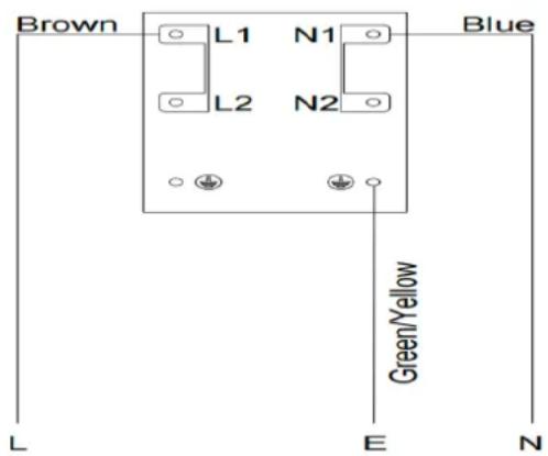
This hob must be connected to the main power supply by the suitable qualified person. Before connecting the hob to the mains power supply, check that:
- the domestic wiring system is suitable for the power drawn by the hob.
- the voltage corresponds to the value given in the rating plate
- the power supply cable sections can withstand the load specified on the rating plate.
To connect the hob to the mains power supply, do not use adapters, reducers, or branching devices, as they can cause overheating and fire.
The power supply cable must not touch any hot parts and must be positioned so that its temperature will not exceed 75^ C at any point.

Check with an electrician whether the domestic wiring system is suitable without alterations. Any alterations must only be made by a qualified electrician.
text_image
Brown L1 N1 Blue L2 N2 Green/Yellow L E N220-240V 1N\~
- If the power cable is damaged or to be replaced, the operation must be carried out by the after-sale agent with dedicated tools to avoid any accidents.
- If the appliance is being connected directly to the main power supply, the unipolar circuit-breaker must be installed with a minimum opening of 3mm between contacts.
- The installer must ensure that the correct electrical connection has been made and that it is compliant with safety regulations.
- The cable must not be bent or compressed.
• The cable must be checked regularly and replaced by authorized technicians only.
This appliance requires a 32 Amp Miniature Circuit Breaker.
DISPOSAL OF THE APPLIANCE
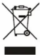
DISPOSAL: Do not dispose this product as unsorted municipal waste. Collection of such waste separately for special treatment is necessary.
This appliance is labeled in compliance with European directive
2011/65/EU for Waste Electrical and Electronic Equipment (WEEE). By ensuring that this appliance is disposed of correctly, you will help prevent any possible damage to the environment and to human health, which might otherwise be caused if it were disposed of in the wrong way.
The symbol on the product indicates that it may not be treated as normal household waste. It should be taken to a collection point for the recycling of electrical and electronic goods.
This appliance requires specialist waste disposal. For further information regarding the treatment, recovery and recycling of this product, please contact your local council, your household waste disposal service, or the shop where you purchased it.
For more detailed information about treatment, recovery and recycling of this product, please contact your local city office, your household waste disposal service or the shop where you purchased the product.
WARRANTY & AFTER SALES SERVICE
Observe all safety and warning information during operation (see the "General Safety Instructions" section).
In the event of a fault which you cannot remedy yourself, please contact Linärie.
Warranty
The manufacturer's warranty for this appliance is 2 years.
After sales service
The contact details for Linärie are given at the beginning and of these instructions.
When contacting Linärie, please quote the model and serial number of your appliance. These can be found on the data plate, after removing the grease filter.
Record model & serial number
Model: ..... Serial Number: ....
Register your product www.linarie.com.au
Replacement of spare parts
Incorrect components can lead to personal injury or damage to the appliance. Use only genuine original Linärie spare parts.
Modifications, additions or alterations to the appliance can lead to safety risks. If spare parts or accessories from other manufacturers are used, the warranty will be invalidated, and Linärie cannot accept liability.
Please check www.linarie.com.au for more information.
LIKE TO KNOW MORE?
For further information on all Linärie appliances, or to obtain detailed dimension and installation information, phone or email our Customer Care team or visit our website:
Australia
hello@linarie.com.au
www.linarie.com.au
Follow Us
@Linarie.Appliances

© Linärie
Operating and installation instructions: Original √ Translation
Mart Online Services Pty Ltd. ACN 657 824 050
Linärie Contact hello@linarie.com.au www.linarie.com.au
The distribution and duplication of this document, as well as the use and disclosure of its contents are prohibited unless expressly authorised.
These operating and installation instructions have been drawn up with the greatest of care. But it cannot be ruled out that subsequent technical modifications have not yet been incorporated or the relevant content has not yet been adapted. Please accept our apologies in this eventuality. An updated version can be requested from our team. Subject to printing errors and mistakes.
© Linärie
All rights reserved.