XN120B - Ice Maker Vevor - Free user manual and instructions
Find the device manual for free XN120B Vevor in PDF.

| Brand | Vevor |
| Model | XN120B |
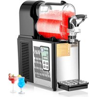
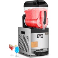
| Product Type | Slush machine |
| Usage | Professional and domestic |
| Bowl capacity | 12 liters |
| Number of bowls | 1 |
| Power supply | 220-240 V ~ 50/60 Hz |
| Ambient temperature range | 5 °C to 32 °C |
| Main functions | Mixing, slush production, cold drink, integrated lighting |
| Control panel | Digital with dedicated keys (Mix, Slush, Cold Drink, Light, Set) |
| Concentration adjustment | Adjustable via panel (adjustable freezing temperature) |
| Protections | Frozen bowl alarm, low voltage protection, emergency stop |
| Bowl material | Stainless steel (food grade) |
| Cleaning | Disassemble bowl, lid and tap; wash with warm soapy water and disinfect |
| Regular maintenance | Drain and clean water tank; annual maintenance by a technician |
| Lamp replacement | Possible after power cut |
| Spare parts | Use only genuine Vevor parts |
| Compliance | FCC Part 15, WEEE directive (2012/19/EU) |
| Warranty | Electronic warranty via www.vevor.com/support |
Frequently Asked Questions - XN120B Vevor
User questions about XN120B Vevor
0 question about this device. Answer the ones you know or ask your own.
Ask a new question about this device
Download the instructions for your Ice Maker in PDF format for free! Find your manual XN120B - Vevor and take your electronic device back in hand. On this page are published all the documents necessary for the use of your device. XN120B by Vevor.
USER MANUAL XN120B Vevor
Technical Support and E-Warranty Certificate www.vevor.com/support
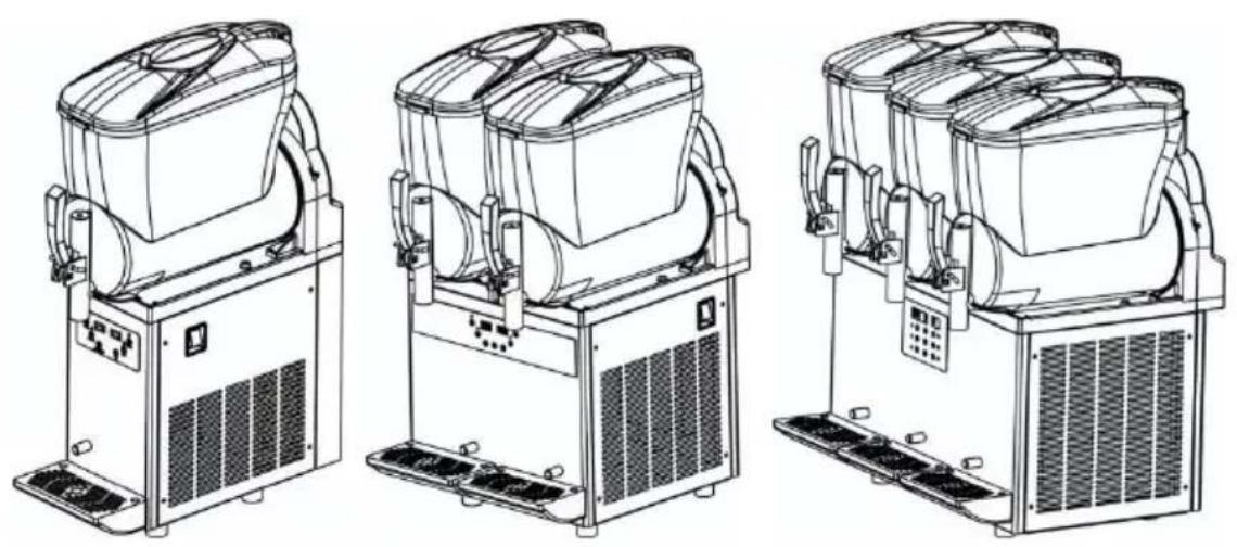
SLUSH MACHINE
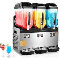
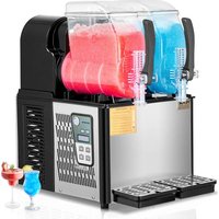
MODEL:XN120B XN240B XN360B
We continue to be committed to provide you tools with competitive price. "Save Half", "Half Price" or any other similar expressions used by us only represents an estimate of savings you might benefit from buying certain tools with us compared to the major top brands and does not necessarily mean to co all categories of tools offered by us. You are kindly reminded to verify carefully when you are placing an order with us if you are actually Saving Half in comparison with the top major brands.
MODEL:XN120B XN240B XN360B
natural_image
Technical line drawings of three industrial slurry machines with heat sinks and ventilation grilles (no text or labels)NEED HELP? CONTACT US!
Have product questions? Need technical support? Please feel free to contact us:
Technical Support and E-Warranty Certificate www.vevor.com/support
This is the original instruction, please read all manual instructions carefully before operating. VEVOR reserves a clear interpretation of user manual. The appearance of the product shall be subject to product you received. Please forgive us that we won't inform you and there are any technology or software updates on our product.


Warning-To reduce the risk of injury, user must read instructions manual carefully.
CAUTION: Changes or modifications not expressly approved by the party responsible for compliance cou the user's authority to operate the equipment!
This device complies with Part 15 of the FCC Rules Operation is subject to the following two conditions:
1) This product may cause harmful interference.
2)This product must accept any interference received, including interference that may cause undesired operat WARNING: Changes or modifications to this product n expressly approved by the party.responsible for compli could void the user's authority to operate the product. Note: This product has been tested and found to co the limits for a Class B digital device pursuant to Pa the FCC Rules, These limits are designed to provide reasonable protection against harmful interference in a residential installation.
This product generates, uses and can radiate radio frequency energy, and if not installed and used in accordance with the instructions, may cause harmful interference to radio communications. However, there is guarantee that interference will not occur in a particular installation. If this product does cause harmful interference or television reception, which can be determined turning the product off and on, the user is encouraged to correct the interference by one or more of the form measures.
- Reorient or relocate the receiving antenna.
- Increase the distance between the product and rece
- Connect the product to an outlet on a circuit differ that to which the receiver is connected.
| • Consult the dealer or an experienced radio/TV tech for assistance. | |
 | This product is subject to the provision of European 2012/19/EC. The symbol showing a wheelie bin cross through indicates that the product requires separate re collection in the European Union. This applies to the and all accessories marked with this symbol. Products marked as such may not be discarded with normal d waste, but must be taken to a collection point for re electrical and electronic devices |
Table of Contents
1. Product Description
1.1. Product Use
1.2. Main Parts
1.3. Technical Parameters
1.4. Control Panel Description and Function
2. Safety
2.1. Safety Rules
2.2. Stop Function
3. Operation and Storage
3.1. Packaging
3.2. Transport and Operation
3.3. Storage
4. Installation
4.1. Mounting Location
4.2. Power Connection
5. Operation
5.1. Materials Preparation
5.2 Starting The Slush Machine
5.3. Slush Concentration Adjustment
5.4. Slush Production
5.5. Emergency Situation
6. Cleaning and Maintenance
6.1. Empty the Bowl
6.2. Disassemble The Handle Parts
6.3. Remove the Bowl and Lid
6.4. Disassemble The Push Handle
6.5. Wash and Disinfect the Components
6.6. Reassemble The Cleaned Parts
6.7. Rinse Cycle
6.8. Clean The Water Box
6.9. Lamp Cover
6.10. Lamp Replacement
6.11. Regular Maintenance
7. Wiring diagram
1. Product Description
1.1. Product Usage
This machine is suitable for making slush and cold drinks, and the operation of this slush machine must comply with current standards.
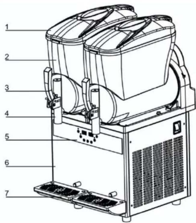
1.2. Main Parts
The main components of the machine are as follows:
- Bowl lid
- Bowl
- Discharge wrench
- Discharge port
- Control Panel
- Chassis
- Water tray
1.3. Technical Parameters
Model: please see the nameplate
Size: please see the nameplate
Maximum output power (watts): please see the nameplate
Operating voltage (volts): please See the nameplate on the side of the machine
Operating ambient temperature range: from 5 degree to 32 degrees
Bowl Number: 1/2/3
Single bowl capacity (L):12
Sound pressure level: minimum 65 dB
Grade: N
* Tip: The Factory reserves the right to alter the machine without prompting.
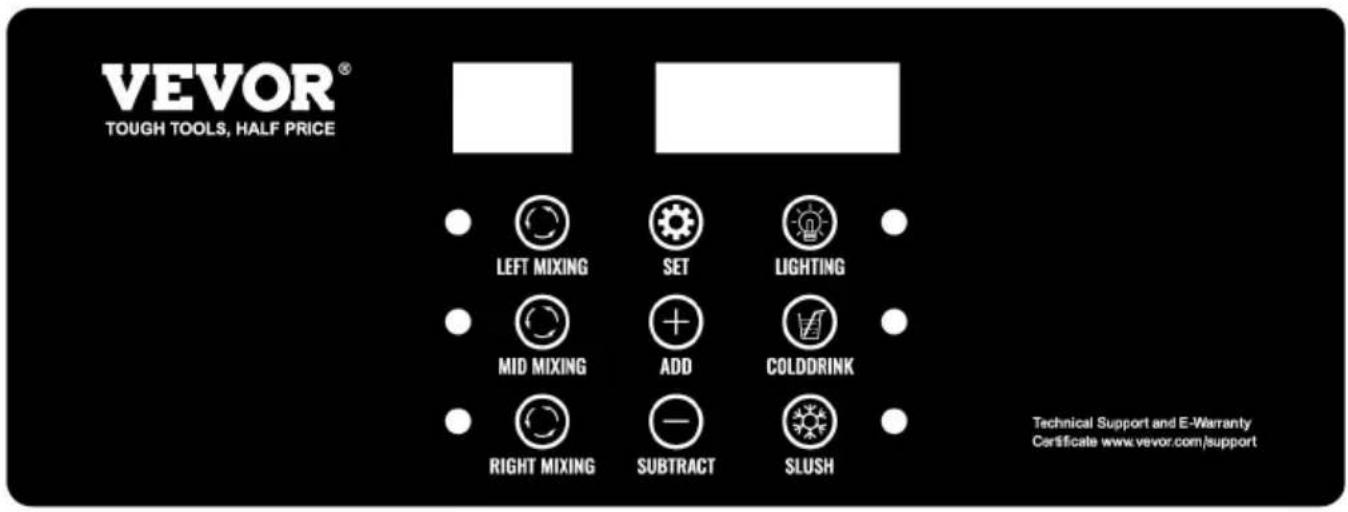
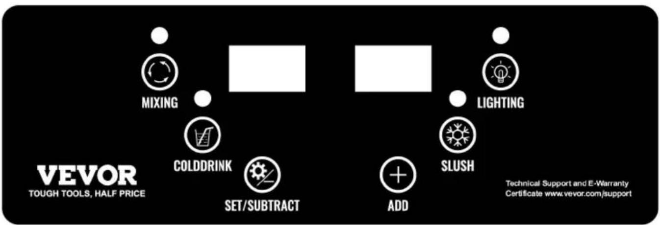
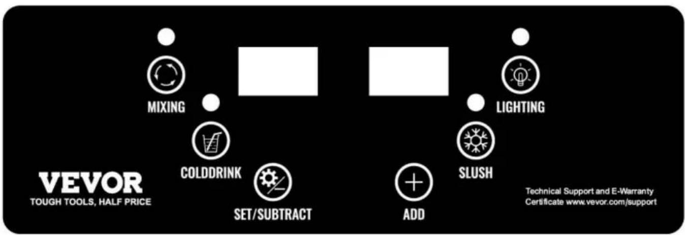
1.4Control Panel Description and Function
1.4.1 Panel Diagram:
MODEL: XN360B
MODEL: XN240B

MODEL: XN120B
| Model | Code | Factory Setting | Meaning |
| XN120B | SL1 | -2.0°C | Slush temperature |
| Cd1 | 5.0°C | Cold drink temperature | |
| XN240B | SL1 | -2.0°C | Slush temperature for left bowl |
| SL2 | -2.0°C | Slush temperature for right bowl | |
| Cd1 | 5.0°C | Cold drink temperature for left bo | |
| Cd2 | 5.0°C | Cold drink temperature for right bo | |
| XN360B | S1 | -2.0°C | Slush temperature for left bowl |
| S2 | -2.0°C | Slush temperature for middle bow | |
| S3 | -2.0°C | Slush temperature for right bowl | |
| C1 | 5.0°C | Cold drink temperature for left bo | |
| C2 | 5.0°C | Cold drink temperature for middle bo | |
| C3 | 5.0°C | Cold drink temperature for right bo |
| Code | Factory Setting | Meaning |
| P00 | 0.2 (Degrees) | Slush temperature return difference value |
| P01 | 0 (Degrees) | The maximum setting temperature |
| P02 | -15.0 (Degrees) | The minimum setting temperature |
| P03 | 10 (Minutes) | Press protection time |
| P04 | 110V:85(V)220V:185(V) | Low voltage protection value |
| P05 | 1 (0: Disable 1 Enable) | Voltage protection enabled |
| P06 | 0.0 | # 1 bowl temperature correction |
| P07 | 0.0 | # 2 bowl temperature correction |
| P08 | 0.0 | # 3 bowl temperature correction |
| P09 | 2.0 (Degrees) | Cold drink temperature return differer value |
1.4.2 Introduction of Function and Set
( Model:XN120B)
- Press “Mixing” key, turn on mixing function, mixing light is on. Pre “Mixing” key again to turn off the mixing function.
- Press the “Cold Drink” key (mixing function must be turned on, of the Cold Drink key does not work), turn on the cold drink function, and drink light is on (the compressor is powered on) or cold drink light for (compressor is powered off), then press the “Cold Drink” key again to the cold drink function.
- Press the “Slush” key (mixing function must be turned on, otherwise Slush key does not work) to open the slush function, and slush light (the compressor is powered on) or slush light flashes (compressor is powered off), then press the “Slush” key again to close the slush fur 4. Press the “Lighting” key to turn on the light, and then press the key again to turn off the light.
- Press "Set" key, enter the user parameter setting state. At this tin press the "Set" key to change the setting object, press "Subtract(-)" k and "Add(+) " key to change the value. After 5 seconds without opera the key, the system will exit and save the setting value automatically. 6.Hold down "Subtract(-)" key and "Add(+) " key for 5 seconds at the time to enter the Factory parameter setting mode, press the "Lighting" to change the object, press "Subtract(-)" key and "Add(+) " key to cha the value. The system will exit and save the parameters automatically 5 seconds without any operation of keys.
(Model:XN240B)
- Press “Left Mixing” key, turn on left mixing function, left mixing light. Press “Left Mixing” key again to turn off the left mixing function.
- Press “Right Mixing” key, turn on right mixing function, right mixing is on. Press “Right Mixing” key again to turn off the right mixing fun
- Press the “Cold Drink” key (a Mixing function must be turned on, otherwise the Cold Drink key does not work), turn on the cold drink and cold drink light is on (the compressor is powered on) or cold drink
flashes (compressor is powered off), then press the “Cold Drink” key to close the cold drink function.
-
Press the “Slush” key (a Mixing function must be turned on, other the Slush key does not work) to open the slush function, and slush on (the compressor is powered on) or slush light flashes (compressor powered off), then press the “Slush” key again to close the slush fur 5. Press the “Lighting” key to turn on the light, and then press the key again to turn off the light.
-
Press “Set” key, enter the user parameter setting state. At this time the “Set” key to change the setting object, press “Subtract(-)” key and “Add(+)” key to change the value. After 5 seconds without operating the system will exit and save the setting value automatically.
-
Hold down "Set" key and "Add(+) "key for 5 seconds at the same enter the Factory parameter setting mode, press the "Set" key to change the object, press "Subtract(-)" key and "Add(+) "key to change the va The system will exit and save the parameters automatically after 5 set without any operation of keys.
(Model:XN360B)
- Press “Left mixing” key, turn on left mixing function, left mixing light Press “Left Mixing” Key again to turn off the left mixing function.
- Press “Mid Mixing” key, turn on mid mixing function, mid mixing lion. Press “Mid Mixing” key again to turn off the mid mixing function.
- Press “Right Mixing” key, turn on right mixing function, right mixing is on. Press “Right Mixing” key again to turn off the right mixing fun
- Press the “Cold Drink” key (a mixing function must be turned on, otherwise the Cold Drink key does not work), turn on the cold drink and cold drink light is on (the compressor is powered on) or cold drink flashes (compressor is powered off), then press the “Cold Drink” key to close the cold drink function.
- Press the “Slush” key (a Mixing function must be turned on, other the Slush key does not work) to open the slush function, and slush on (the compressor is powered on) or slush light flashes (compressor
powered off), then press the Slush key again to close the slush func
-
Press the “Lighting” key to turn on the light, and then press the key again to turn off the light.
-
Press "Set" key, enter the user parameter setting state. At this tin press the "Set" key to change the setting object, press "Subtract(-)" k and "Add(+)" Key to change the value. After 5 seconds without opera the key, the system will exit and save the setting value automatically.
-
Hold down “Subtract(-)” key and “Add(+)” key for 5 seconds at the time to enter the Factory parameter setting mode, press the “Set” key change the object, press “Subtract(-)” key and “Add(+)” key to change value. The system will exit and save the parameters automatically after seconds without any operation of keys.
Notice: when machine works well, please do not changed factory setti
1.4.3 Alarm Code Description
1) "- -": Frozen bowl alarm is given and the compressor and motor working, and resume automatically after 10 minutes.
2)"RH": temperature sensor malfunction alarm. Stop cooling in cold drive function state without affecting slush function.
3)"LLL": low voltage alarm, the whole machine stops. Turn off the power and check the power supply. Restart machine after voltage is stable. show "LLL" frequently, We suggest you connect a voltage stabilizer.
2. Safety
2.1 General Safety Rules
-
Read the entire manual carefully
-
The power cord must meet local safety standards
-
The power cord and the plug size shall be in compliance with the parameters on the machine nameplate, properly grounded, and coupled with applicable switches and circuit breakers. Never operate the machine near flammable or explosive objects.
- No technical modifications to the machine.
- Please do not spray rinsing the machine
- Be sure to follow the instructions to operate the machine.
- Please do not mount the machine on other devices.
- Please do not wash with benzene or other dissolved substances.
- Never block the vents on the side of the machine.
Before cleaning the machine, make sure the machine has been disconnected from the power.
The machine must be repaired by our service center or a trained technician.
* Damage due to improper operation will void our warranty, and Factory will not be responsible for personal injury or property damage.
2.2. Stop Function
Turn off the main switch to stop the machine.
3. Operation and Storage
All operations described in Chapter 4 must be carried out by professi in charge of transporting/handling packaged or unpackaged products. Be sure to use appropriate equipment depending on the nature and v of the goods, as well as relevant stipulations of local regulations.
3.1. Packaging
The goods to be shipped shall be packaged and fixed with foam ins and cardboard or Wooden boxes outside.
3.2. Transport and Handling
In case of physically works needed, it must be completed by at least people.
1) The machine must stay upward when being moved.
2) Pay attention to the packaging and protruding parts.
3.3. Storage
The machine should be cleaned and disinfected before it is put into warehouse.
If the machine is to be put idle for a long time, protective measures taken for its placement location and storage time:
1) The machine shall be placed in enclosed space.
2) Prevent the machine from being hit and squeezed.
3) The machine should be placed in a cool and dry place, not expo moisture and high temperature.
4) Keep the machine away from corrosive substances.
4. Installation
The machine must be installed in a bright, well-ventilated room with a solid floor.
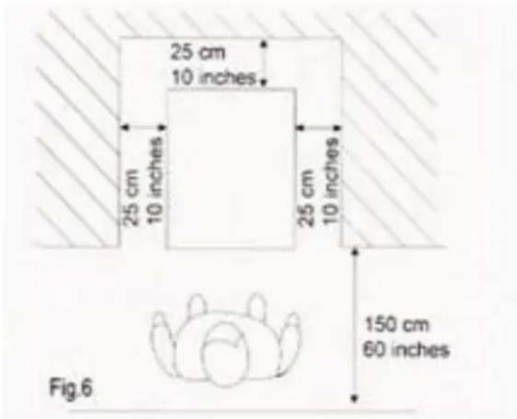
4.1 Mounting Location
-
The floor for the machine to be mounted on must be firm and fl
-
The space should be bright, well-ventilated and clean.
-
Sufficient clearance shall be provided to facilitate unrestricted operation as well as emergency use. *TIP: Leave 25 cm (10 in.) clearance on of the bowl.
* Before using the machine for the first time, all the parts must be and the parts that are in contact with the slush need to be handled for more details, please read relevant section.
4.2. Power Connection
Make sure the main switch is at "0" before
you plug in.
Warning: The power socket must be arranged in a place easily access by the user.
5. Operation
5.1. Material Preparation
Pour the material into the bowl when the machine is off and unpowered Warning: Minimum sugar content should not be less than 13% , as low concentration may damage the machine.
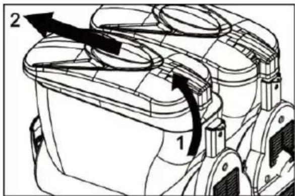
Remove the lid from the bowl according to the following instructions:
- Lift the back of the lid.
- Remove the lid from the front retainer.
- After material was added to the bowl, the lid on the bowl should back.
Warning:
1) Please do not open the lid forcibly.
2) Never add liquid higher than 25 degrees Celsius.
3) When feeding the bowl, be careful not to exceed the maximum line must exceed mixer shaft.
4) Please do not turn on the machine when the lid is not in place. turn off and unplug the machine before removing the lid.
5) Please turn off and unplug the machine before removing any parts the bowl
natural_image
Technical line drawing of a mechanical device with cylindrical components and mounting brackets (no text or symbols)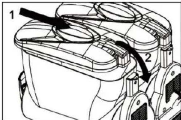
5.2. Starting the Slush Machine
Refer to 1.4. Control Panel Description and Function.
5.3. Slush Concentration Adjustment
Refer to 1.4.2 to Set up Parameters; the bigger position corresponds thicker slush.
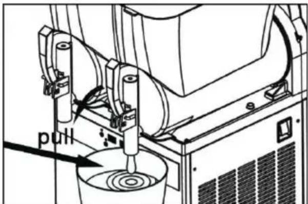
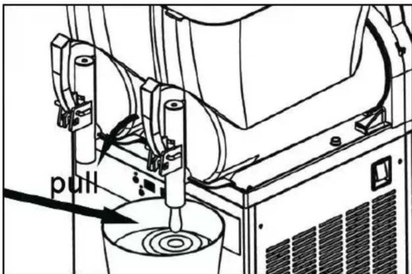
5.4. Slush Production
Pull the handle to produce the slush.
If the machine is not to be used continuously, the following operation required in case of dairy products:
1) Spray water onto the faucet and surrounding area.
(Use a clean cloth to wipe for disinfection at the same time).
2) Before making slush for the customer, please use a small amount product to try first.
5.5 Emergency Situations
1) In extreme emergencies, set the main switch to "0" to turn off the machine.
2) If the machine is stuck, turn off the machine, and contact the senior center or a professional technician.
6. Cleaning and Maintenance
Prior to any cleaning and maintenance of external components of the machine, make sure the main switch is located at position “0” and the machine is not plugged in.
For cleaning and maintenance, follow these instructions:
- Put on protective gloves.
-
Never use soluble and explosive materials.
-
When the machine is powered on and the main switch at position cleaning is prohibited.
6.1 Empty the Bowl
Before cleaning the bowl, please first remove all the previously prepare material.
6.2. Disassemble the handle parts
Please do not dismantle the handle of the machine if there is materi other liquid in the bowl.
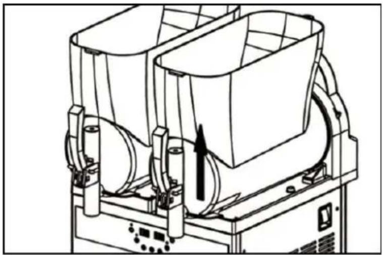
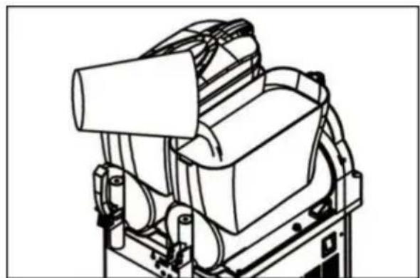
6.3 Remove the bowl and lid
Remove each bowl to ensure that the machine is neat and clean.
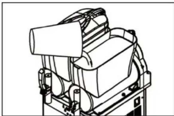
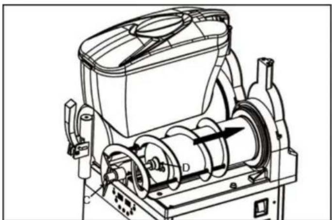
Remove the bowl as follows:
- Remove the lid as shown in the figure.
- Raise the front part of the bowl to loosen it.
- Gently push and rotate its back to remove the bowl.
- Take out the mixer shaft and remove the seal ring.
natural_image
Technical line drawing of a mechanical device with no visible text or symbols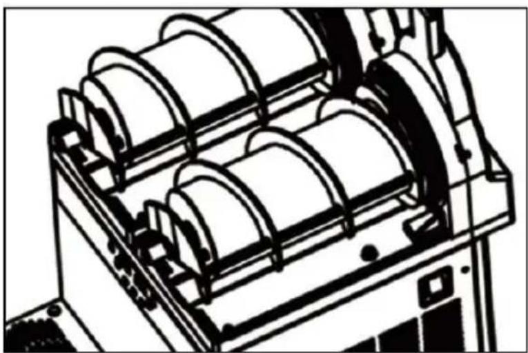
natural_image
Technical line drawing of a mechanical device with multiple cylindrical components (no text or symbols)6.4 Disassemble the push handle
-
Put the bowl on a smooth surface to facilitate the removing of the Pull the "U" towards you and push the tap with your other hand.
-
Unlock the spring, hold it down, push horizontally and finally releas
-
Unscrew the bar from the tap.
-
Hold down the two rubber flanges, and separate the red rubber from all parts must be washed with hot water and soap, and fully air dried being re-assembled.
6.5. Wash and disinfect the components
All previously removed parts must be thoroughly cleaned and disinfected. Important note: Disinfection procedures must comply with the machine operation guidelines.
Please follow the instructions below to ensure proper disinfection:
- Dispense the antiseptic solution into the container (2% sodium hypochlorite mixed with water).
- Thoroughly wash the bowl, lid and evaporator with a soaked sponge
- Thoroughly clean with water.
- Pour disinfectant into another container.
- Dip the disassembled parts into the disinfectant.
- Soak the parts in disinfectant for 30 minutes.
- Wash thoroughly with water again.
- Air dry the parts at a clean place.
- Reassemble as described in section 6.5.
- Rinse thoroughly with water before using the machine.
Caution: Do not immerse the lid with the lamp in any solution. Before cleaning and disinfecting the lid, please remove the lid as described i previous section. In order to properly clean the lamp cover, these ste must be followed:
- Wipe the bottom of the lid (the part contact with the machine) with clean, damp cloth.
- Wipe the outside of the machine with a clean, damp cloth.
- Use a disinfectant soaked sponge to disinfect the bottom of the lid. And be sure not to wet the lid's interface with the machine.
- Allow operation for 30 minutes.
- Rinse twice or more. Only the bottom of the lid needs to be wip clean water sponge.
- Put the lid on a clean flat surface to dry. First, dry the bottom at the external parts with a clean cloth.
- Install the lid back after the bowl has been cleaned and disinfected. Never clean the machine when the lid is installed on it.
6.6 Reassemble the cleaned parts
All cleaned and disinfected components must be carefully reinstalled, a components must be fully lubricated for the machine to work more efficiently.
Clean the tray and grid separately with warm water.
Dry all the parts.
Put the grid back over the tray.
Install the seal ring of the mixer shaft as shown.
natural_image
Technical line drawing of a mechanical assembly with pulleys and a central hub (no text or symbols)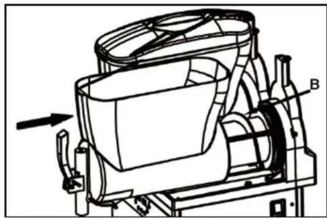
natural_image
Technical line drawing of a mechanical device with labeled component B, showing internal components and directional arrow (no text or symbols beyond label)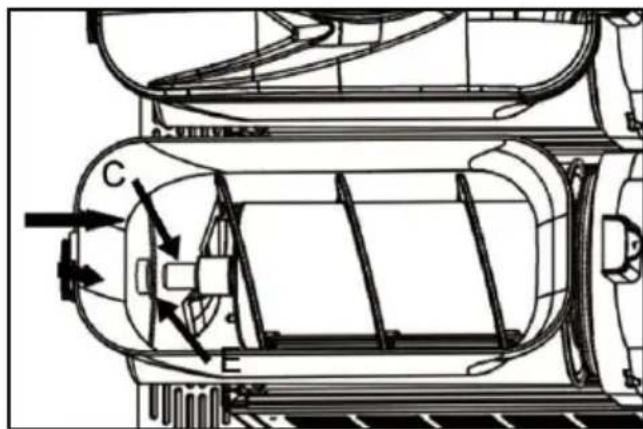
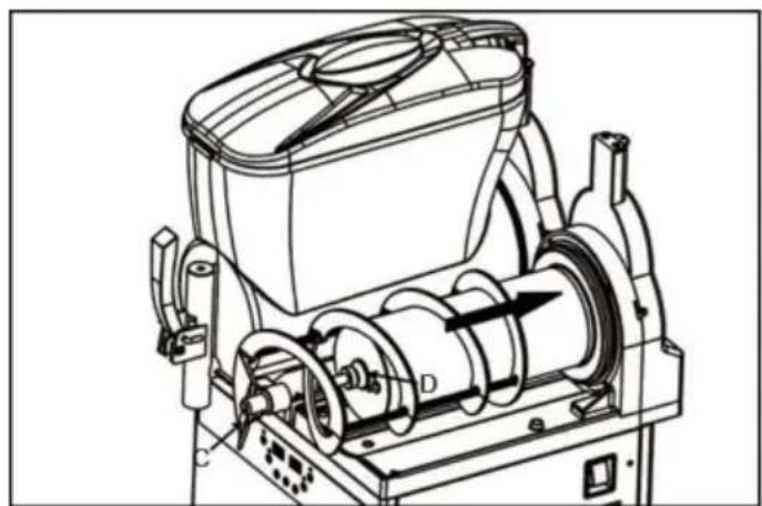
natural_image
Technical line drawing of a mechanical device with labeled components (no text or symbols present)Important note: Always check the integrity of the seal ring. If the seal broken, it should be replaced with a new one.
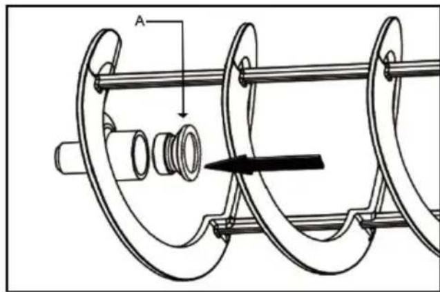
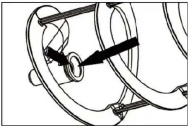
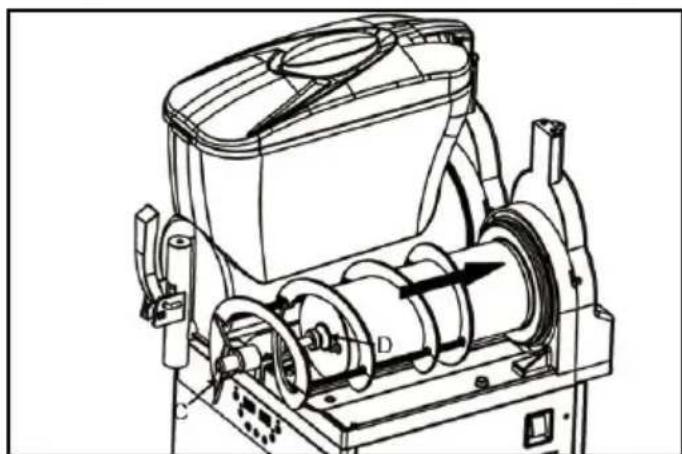
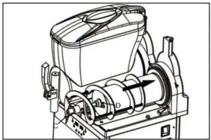
Use the supplied Vaseline to lubricate the seal ring in the illustrated Install the mixer shaft as shown; install the head of the mixer shaft the shaft (D).
Tips: Rotate it into the first half of the bowl and push the bowl to designated position in contact with the seal ring (B).
1) Align the head of the mixer shaft with the interface inside the bow down the bowl, and follow instructions below to reinstall the faucet.
2) Lubricate the joints fully with the supplied Vaseline.
3) Put the piston in the designated position, and push the handle un connects the faucet.
6.7 Rinse cycle
Before starting the machine, it must be cleaned circularly.
Proceed as follows:
- Fill the bowl with water.
- Let the machine stir for 5 minutes.
- Turn off the machine, and open the tap to empty the water in the
6.8 Clean the water box
The water box should be emptied and cleaned regularly.
Pull up the water box with the lid and then pull it out.
6.9 Lamp cover
6.10 Lamp replacement
When replacing the lamp, the main switch must be turned off and the power must be disconnected.
Remove the protective cap and unscrew the cover screws; use suitab screwdriver to operate.
6.11 Regular maintenance
1) The machine must be maintained regularly by professional technicia (at least once a year).
2) Regular inspection can ensure that all components are installed in and the machine can run safely.
3) Any damaged components must be replaced with original parts.
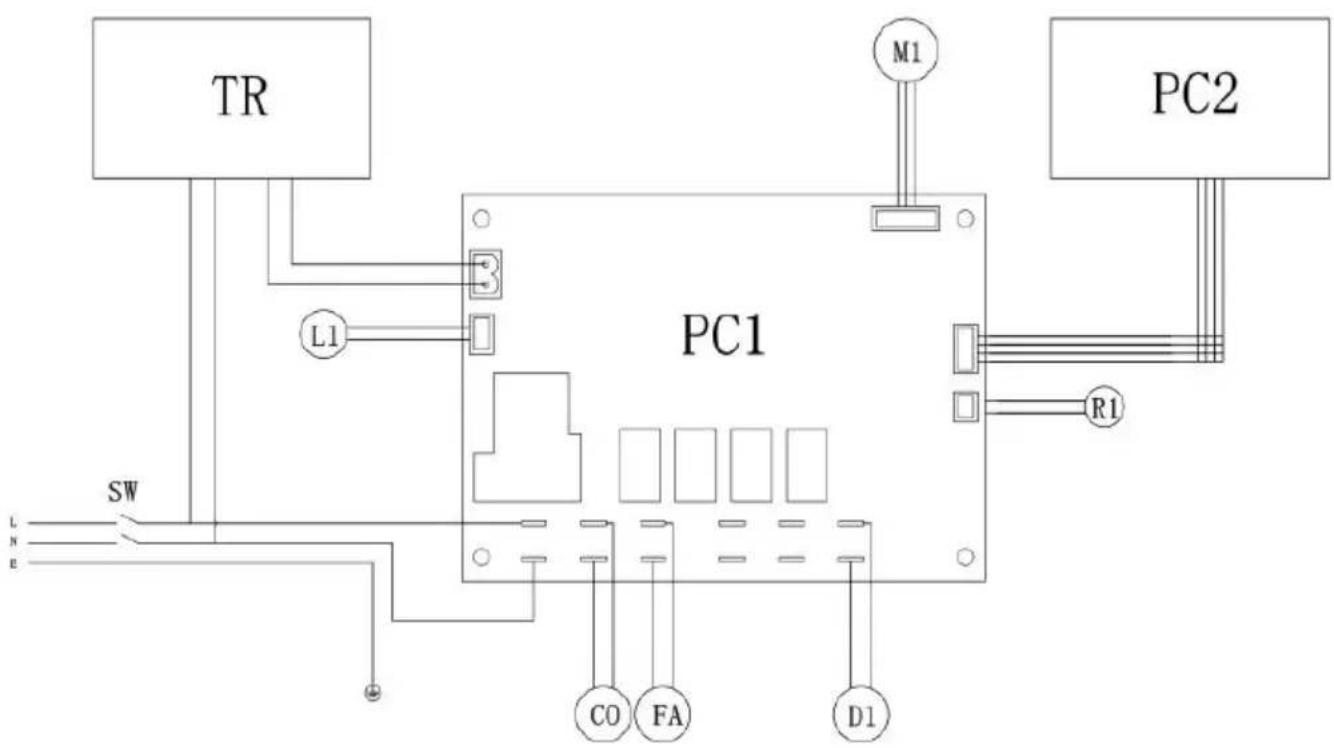
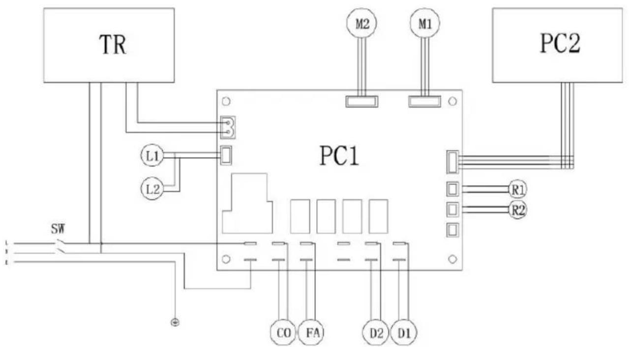
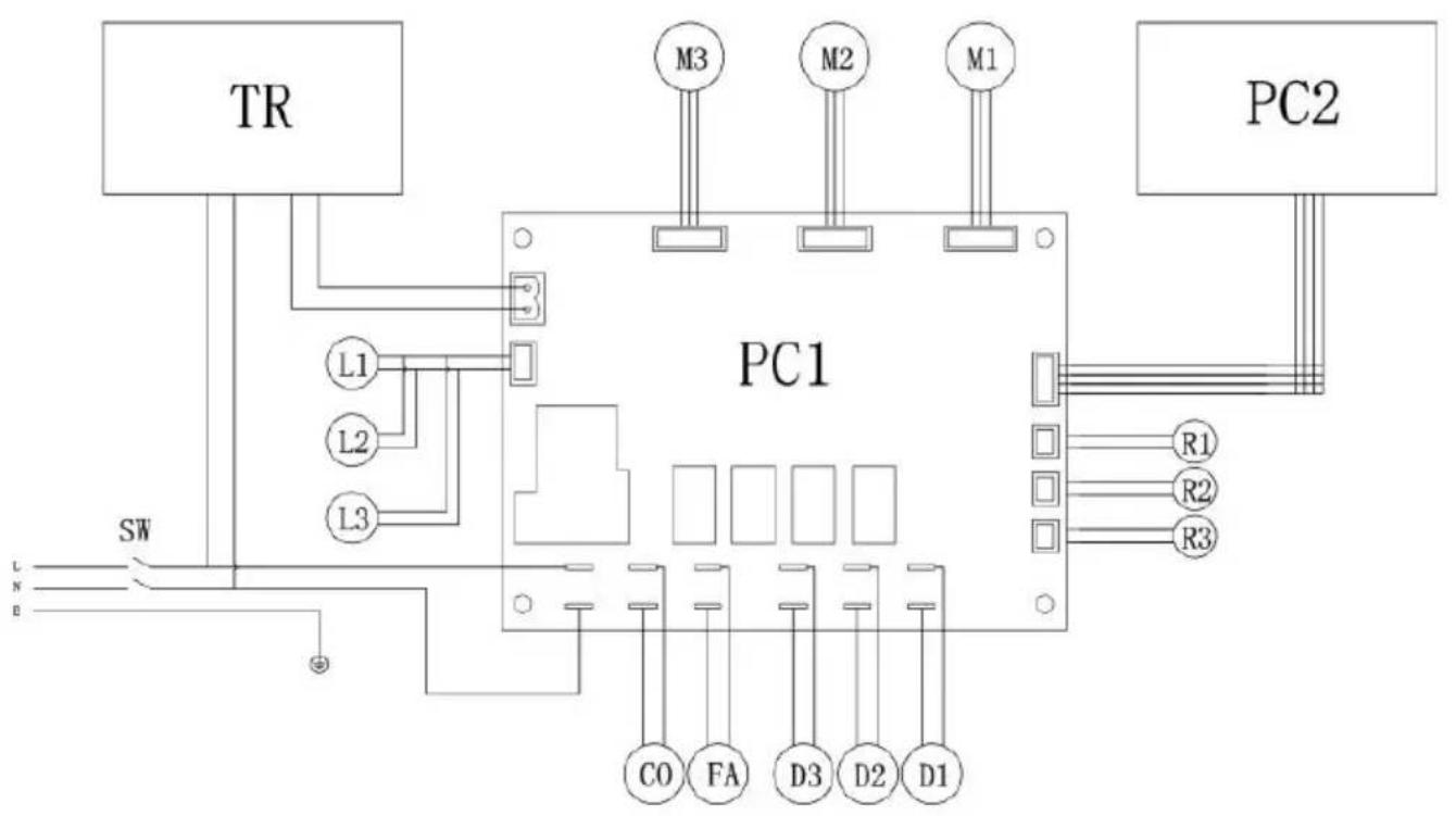
7. Wiring diagram
flowchart
graph TD
    TR["TR"] -->|L1| PC1["PC1"]
    PC1 -->|M1| PC2["PC2"]
    PC1 -->|R1| PC2
    SW["SW"] -->|L1| PC1
    SW -->|E| PC1
    PC1 -->|C0| C0
    PC1 -->|FA| FA
    PC1 -->|D1| D1
PCI-Vain PC Board, PC2-Dispaly Panel,\$i Switch,00-Coapressar,FA-Fan,1R-TransformerMI-Stirring llotor, LI-IED Lighting, RI-Teaperature Sensor.
flowchart
graph TD
    TR["TR"] --> L1["L1"]
    TR --> L2["L2"]
    L1 --> PC1["PC1"]
    L2 --> PC1
    PC1 --> M2["M2"]
    PC1 --> M1["M1"]
    PC1 --> PC2["PC2"]
    SW["SW"] --> PC1
    R1["R1"] --> PC1
    R2["R2"] --> PC1
    C0["C0"] --> PC1
    FA["FA"] --> PC1
    D2["D2"] --> PC1
    D1["D1"] --> PC1
PCI-Main Pc Board, p2-Dispsly Panel, Sh-Switch, 00-Compressor, FA-Fa TR-TransformerMI/1/%2-Stirring Whotor, II/I2-ED Lighting, RI/R2-Temperature Sensor, DI/02-Solenoid Valve
flowchart
graph TD
    TR["TR"] --> L1["L1"]
    TR --> L2["L2"]
    TR --> L3["L3"]
    L1 --> PC1["PC1"]
    L2 --> PC1
    L3 --> PC1
    PC1 --> M3["M3"]
    PC1 --> M2["M2"]
    PC1 --> M1["M1"]
    PC1 --> R1["R1"]
    PC1 --> R2["R2"]
    PC1 --> R3["R3"]
    SW["SW"] --> L1
    SW --> L2
    SW --> L3
    PC1 --> CO["C0"]
    PC1 --> FA["FA"]
    PC1 --> D3["D3"]
    PC1 --> D2["D2"]
    PC1 --> D1["D1"]
PCI-Main Pc Board, p2-DispalyPanel, SNSwitch, C0 Coapressor, FA-Far TR-TransformerM1/1/M2/M3-Stirring notor, L1/L2/L3-LED Lighting.R1/R2/R3-Temperature Sensor,DI/D2/03-Solenoid Valve
VEVOR®
TOUGH TOOLS, HALF PRICE
Technical Support and E-Warranty Certificate
www.vevor.com/support
VEVOR®
TOUGH TOOLS, HALF PRICE
natural_image
Technical line drawings of three industrial fan or fan unit machines with heat sinks and ventilation systems (no text or labels)BESOIN D'AIDE? CONTACTEZ-NOUS!
MODÈLE : XN240B

MODÈLE : XN120B

natural_image
Technical line drawing of a mechanical device with cylindrical components and mounting brackets (no text or symbols)
natural_image
Technical line drawing of a mechanical device with no visible text or symbols
natural_image
Technical line drawing of a mechanical device with multiple cylindrical components (no text or symbols)natural_image
Mechanical diagram showing a pulley system with rotating components and directional arrows (no text or labels)
natural_image
Technical line drawing of a mechanical device with labeled component B (no text or symbols beyond label)

natural_image
Technical line drawing of a mechanical device with labeled components (no text or symbols present)MODELL: XN240B

MODELL: XN120B

natural_image
Technical line drawing of a mechanical device with cylindrical components and mounting brackets (no text or symbols)
natural_image
Technical line drawing of a mechanical device with no visible text or symbols
natural_image
Technical line drawing of a mechanical device with multiple cylindrical components (no text or symbols)natural_image
Mechanical diagram showing a pulley system with rotating components and directional arrows (no text or labels)
natural_image
Technical line drawing of a mechanical device with labeled component B (no text or symbols beyond label)

natural_image
Technical line drawing of a mechanical device with labeled components (no text or symbols present)www.vevor.com/support
VEVOR®
TOUGH TOOLS, HALF PRICE
natural_image
Technical line drawings of three industrial fan or cooling unit machines with heat sinks and ventilation systems (no text or labels)MODELLO: XN240B

MODELLO: XN120B

natural_image
Technical line drawing of a mechanical device with cylindrical components and mounting brackets (no text or symbols)
natural_image
Technical line drawing of a mechanical device with no visible text or symbols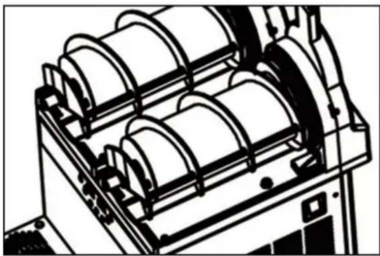
natural_image
Technical line drawing of a mechanical device with multiple cylindrical components (no text or symbols)natural_image
Mechanical diagram showing a pulley system with rotating components and directional arrows (no text or labels)
natural_image
Technical line drawing of a mechanical device with labeled component B (no text or symbols beyond label)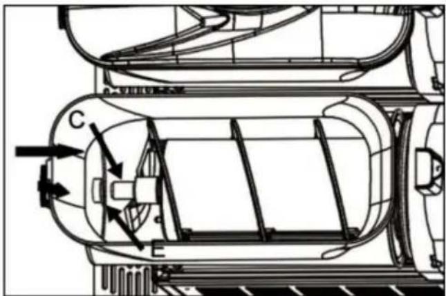
natural_image
Technical line drawing of a mechanical device with internal components and labeled parts (no text or symbols)elettronica www.vevor.com/support
VEVOR®
TOUGH TOOLS, HALF PRICE
natural_image
Technical line drawings of three industrial fan or cooling unit machines with heat sinks and ventilation systems (no text or labels)MODELO: XN240B

MODELO: XN120B

natural_image
Technical line drawing of a mechanical device with cylindrical components and mounting brackets (no text or symbols)
natural_image
Technical line drawing of a mechanical device with no visible text or symbols
natural_image
Technical line drawing of a mechanical device with multiple cylindrical components (no text or symbols)natural_image
Mechanical diagram showing a pulley system with rotating components and directional arrows (no text or labels)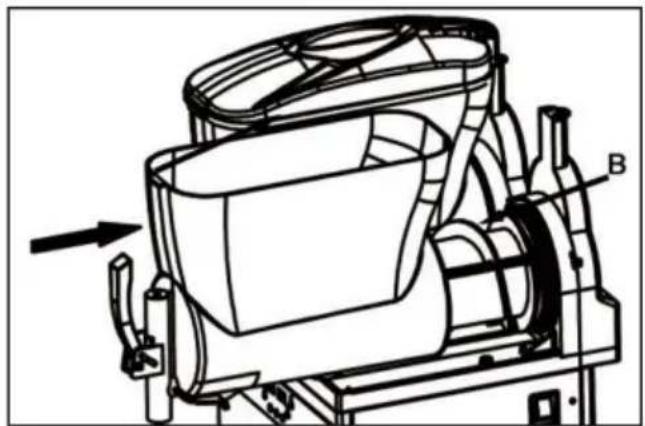
natural_image
Technical line drawing of a mechanical device with labeled component B (no text or symbols beyond label)
natural_image
Technical line drawing of a mechanical device with labeled components (no text or symbols present)natural_image
Technical line drawings of three industrial fan or fan unit machines with heat sinks and ventilation systems (no text or symbols)POTRZEBUJESZ POMOCY? SKONTAKTUJ SIĘ Z NAMI!
MODEL: XN240B

MODEL: XN120B

natural_image
Technical line drawing of a mechanical device with cylindrical components and mounting brackets (no text or symbols)
natural_image
Technical line drawing of a mechanical device with no visible text or symbols
natural_image
Technical line drawing of a mechanical device with multiple cylindrical components (no text or symbols)6.4 Zdemontuj uchwyt do pchania
natural_image
Mechanical diagram showing a pulley system with rotating components and directional arrows (no text or labels)
natural_image
Technical line drawing of a mechanical device with labeled component B (no text or symbols beyond label)

natural_image
Technical line drawing of a mechanical device with labeled components (no text or symbols)natural_image
Technical line drawings of three industrial fan or cooling unit machines with heat sinks and ventilation systems (no text or labels)HULP NODIG? NEEM CONTACT MET ONS OP!
Demonteer de handgreeponderdelen
1.3. Technische parameters
MODEL: XN240B

MODEL: XN120B

natural_image
Technical line drawing of a mechanical device with cylindrical components and mounting brackets (no text or symbols)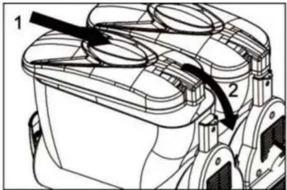
5.2. De slushmachine starten
natural_image
Technical line drawing of a mechanical device with no visible text or symbols
natural_image
Technical line drawing of a mechanical device with multiple cylindrical components (no text or symbols)6.4 Duwhandgreep demonteren
natural_image
Mechanical diagram showing a pulley system with rotating components and directional arrows (no text or labels)
natural_image
Technical line drawing of a mechanical device with labeled component B (no text or symbols beyond label)

natural_image
Technical line drawing of a mechanical device with labeled components (no text or symbols)garantiecertificaat www.vevor.com/support
VEVOR®
TOUGH TOOLS, HALF PRICE
natural_image
Technical line drawings of three industrial fan or cooling unit machines with heat sinks and ventilation systems (no text or labels)BEHÖVER HJÄLP? KONTAKTA OSS!
1.3. Tekniska parametrar
MODELL: XN240B

MODELL: XN120B


natural_image
Technical line drawing of a mechanical device with cylindrical components and mounting brackets (no text or symbols)
5.2. Starta Slush Machine
natural_image
Technical line drawing of a mechanical device with no visible text or symbols
natural_image
Technical line drawing of a mechanical device with multiple cylindrical components (no text or symbols)6.4 Demontera körhandtaget
natural_image
Mechanical diagram showing a pulley system with rotating components and directional arrows (no text or labels)
natural_image
Technical line drawing of a mechanical device with labeled component B (no text or symbols beyond label)
natural_image
Technical line drawing of a mechanical device with labeled components (no text or symbols)www.vevor.com/support