VBPYCE-110 - Thermostat Vevor - Free user manual and instructions
Find the device manual for free VBPYCE-110 Vevor in PDF.

User questions about VBPYCE-110 Vevor
0 question about this device. Answer the ones you know or ask your own.
Ask a new question about this device
Download the instructions for your Thermostat in PDF format for free! Find your manual VBPYCE-110 - Vevor and take your electronic device back in hand. On this page are published all the documents necessary for the use of your device. VBPYCE-110 by Vevor.
USER MANUAL VBPYCE-110 Vevor
Technical Support and E-Warranty Certificate
www.vevor.com/support
Pool Heat Pump
Model: VBPYCE-70/VBPYCE-110/VBPYCE-150/VBPYCE-210
We continue to be committed to provide you tools with competitive price "Save Half", "Half Price" or any other similar expressions used by us on represents an estimate of savings you might benefit from buying certain tools with us compared to the major top brands and does not necessarily mean to all categories of tools offered by us. You are kindly reminded to verify car when you are placing an order with us if you are actually Saving Half in comparison with the top major brands.
Model: VBPYCE-70/VBPYCE-110/VBPYCE-150/VBPYCE-210
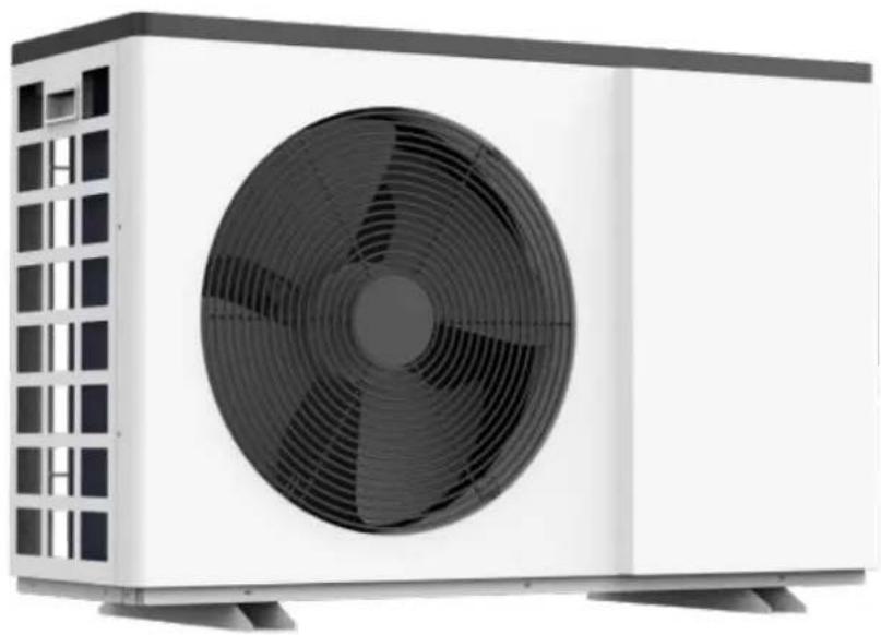
natural_image
Exterior view of a white industrial air conditioning unit with a black fan blade (no text or symbols visible)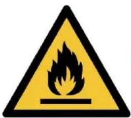

NEED HELP? CONTACT US!
Have product questions? Need technical support? Please feel free to contact Technical Support and E-Warranty Certificate www.vevor.com/support
This is the original instruction, please read all manual instructions carefully by operating. VEVOR reserves a clear interpretation of our user manual. The appe of the product shall be subject to the product you received. Please forgive us won't inform you again if there are any technology or software updates on our
CONTENTS
1.FOREWORD 3
1.1. Read the Manual Before Operation 3
1.2. The Symbol Description of the Device 7
1.3. Statement....7
1.4. Safety Factors 8
2. OVER VIEW OF THE UNIT ....10
2.1. Accessories Supplied With the Unit 10
2.2. Dimensions of the Unit 10
2.3.Main Parts of the Unit....-11-
2.4. Operation Range - 15 -
2.5. Parameter of the Unit....- 15 -
3. INSTALLATION AND CONNECTION....- 16 -
3.1. Transportation....- 16 -
3.2. Notice Before Installation....- 17 -
3.3. Installation Instruction ...... - 17 -
3.4. Trial After Installation - 20 -
4. Remoter controller operation guidance ...... 错误!未定义书签。
1.1. Read the Manual Before Operation
WARNING
Do not use means to accelerate the defrosting process or to clean, other than those recommend the manufacturer. The appliance shall be stored in a room without continuously operating ignito sources (for example: open flames, an operating gas appliance or an operating electric heater. Do not pierce or burn.
Be aware that refrigerants may not contain an odour.
Initial safety checks shall include:
①That capacitors are discharged: this shall be done in a safe manner to avoid possibility of sparking;
②That no live electrical components and wiring are exposed while charging, recovering or purging the system;
③That there is continuity of earth bonding.
Checks to the area
Prior to beginning work on systems containing flammable refrigerants, safety checks are necessary to ensure that the risk of ignition is minimized. For repair to the refrigerating system, the following precautions shall be completed prior to conducting work on the system
Work procedure
Work shall be undertaken under a controlled procedure so as to minimize the risk of a flan or vapour being present while the work is being performed.
General work area
All maintenance staff and others working in the local area shall be instructed on the nature being carried out. Work in confined spaces shall be avoided.
Checking for presence of refrigerant
The area shall be checked with an appropriate refrigerant detector prior to and during work, the technician is aware of potentially flammable atmospheres. Ensure that the leak detection equipment being used is suitable for use with flammable refrigerants, i.e. non-sparking, adequate sealed or intrinsically safe.
Presence of fire extinguisher
If any hot work is to be conducted on the refrigerating equipment or any associated parts, fire extinguishing equipment shall be available to hand. Have a dry powder or CO2 fire extir adjacent to the charging area.
No ignition sources
No person carrying out work in relation to a refrigeration system which involves exposing any work that contains or has contained flammable refrigerant shall use any sources of ignition in manner that it may lead to the risk of fire or explosion. All possible ignition sources, including smoking, should be kept sufficiently far away from the site of installation, repairing, removing disposal, during which flammable refrigerant can possibly be released to the surrounding space.
to work taking place, the area around the equipment is to be surveyed to make sure that flammable hazards or ignition risks. “No Smoking” signs shall be displayed.
Ventilated area
Ensure that the area is in the open or that it is adequately ventilated before breaking into conducting any hot work. A degree of ventilation shall continue during the period that the w carried out. The ventilation should safely disperse any released refrigerant and preferably exp externally into the atmosphere.
Checks to the refrigeration equipment
Where electrical components are being changed, they shall be fit for the purpose and to the specification. At all times the manufacturer's maintenance and service guidelines shall be followed in doubt consult the manufacturer's technical department for assistance.
The following checks shall be applied to installations using flammable refrigerants:
①The charge size is in accordance with the room size within which the refrigerant containing parts are installed;
②The ventilation machinery and outlets are operating adequately and are not obstructed;
③If an indirect refrigerating circuit is being used, the secondary circuit shall be checked for the presence of refrigerant;
④Marking to the equipment continues to be visible and legible. Markings and signs that are illegible shall be corrected;
⑤Refrigeration pipe or components are installed in a position where they are unlikely to be exposed to any substance which may corrode refrigerant containing components, unless the components are constructed of materials which are inherently resistant to being corroded or are suitably protected against being so corroded.
Repairs to sealed components
- During repairs to sealed components, all electrical supplies shall be disconnected from the equipment being worked upon prior to any removal of sealed covers, etc. If it is absolutely to have an electrical supply to equipment during servicing, then a permanently operating form detection shall be located at the most critical point to warn of a potentially hazardous situati
- Particular attention shall be paid to the following to ensure that by working on electrical co the casing is not altered in such a way that the level of protection is affected. This shall i damage to cables, excessive number of connections, terminals not made to original specificati damage to seals, incorrect fitting of glands, etc.
Ensure that the apparatus is mounted securely.
Ensure that seals or sealing materials have not degraded to the point that they no longer purpose of preventing the ingress of flammable atmospheres. Replacement parts shall be in accordance with the manufacturer's specifications.
Repair to intrinsically safe components
Do not apply any permanent inductive or capacitance loads to the circuit without ensuring that not exceed the permissible voltage and current permitted for the equipment in use. Intrinsicall components are the only types that can be worked on while live in the presence of a flam atmosphere. The test apparatus shall be at the correct rating.
Replace components only with parts specified by the manufacturer. Other parts may result in ignition of refrigerant in the atmosphere from a leak.
NOTE The use of silicon sealant can inhibit the effectiveness of some types of leak detection
equipment.
Intrinsically safe components do not have to be isolated prior to working on them.
Cabling
Check that cabling will not be subject to wear, corrosion, excessive pressure, vibration, sharp any other adverse environmental effects. The check shall also take into account the effects of continual vibration from sources such as compressors or fans.
Detection of flammable refrigerants
Under no circumstances shall potential sources of ignition be used in the searching for or d refrigerant leaks. A halide torch (or any other detector using a naked flame) shall not be us
Leak detection methods
The following leak detection methods are deemed acceptable for systems containing flammable refrigerants.
Electronic leak detectors shall be used to detect flammable refrigerants, but the sensitivity may adequate, or may need re-calibration. (Detection equipment shall be calibrated in a refrigerant area.) Ensure that the detector is not a potential source of ignition and is suitable for the R used. Leak detection equipment shall be set at a percentage of the LFL of the refrigerant a calibrated to the refrigerant employed and the appropriate percentage of gas (25 % maximum confirmed.
Leak detection fluids are suitable for use with most refrigerants but the use of detergents cc chlorine shall be avoided as the chlorine may react with the refrigerant and corrode the cop pipe-work.
If a leak is suspected, all naked flames shall be removed/extinguished.
If a leakage of refrigerant is found which requires brazing, all of the refrigerant shall be rec the system, or isolated (by means of shut off valves) in a part of the system remote from Oxygen free nitrogen (OFN) shall then be purged through the system both before and during brazing process.
Removal and evacuation
When breaking into the refrigerant circuit to make repairs – or for any other purpose – con procedures shall be used. However, it is important that best practice is followed since flamm consideration. The following procedure shall be adhered to:
①Remove refrigerant;
②Purge the circuit with inert gas;
③Evacuate;
④Purge again with inert gas;
⑤Open the circuit by cutting or brazing.
The refrigerant charge shall be recovered into the correct recovery cylinders. The system shall "flushed" with OFN to render the unit safe. This process may need to be repeated several Compressed air or oxygen shall not be used for this task.
Flushing shall be achieved by breaking the vacuum in the system with OFN and continuing the working pressure is achieved, then venting to atmosphere, and finally pulling down to a This process shall be repeated until no refrigerant is within the system. When the final OFN used, the system shall be vented down to atmospheric pressure to enable work to take place operation is absolutely vital if brazing operations on the pipework are to take place.
Ensure that the outlet for the vacuum pump is not close to any ignition sources and there
available.
Charging procedures
In addition to conventional charging procedures, the following requirements shall be followed:
①Ensure that contamination of different refrigerants does not occur when using charging equipment. Hoses or lines shall be as short as possible to minimize the amount of refrigerant contained cylinders shall be kept upright.
②Ensure that the refrigeration system is earthed prior to charging the system with refrigerant
③Label the system when charging is complete (if not already).
④Extreme care shall be taken not to overfill the refrigeration system. Prior to recharging the system it shall be pressure tested with OFN. The system shall be leak tested on completion of chargi to commissioning. A follow up leak test shall be carried out prior to leaving the site.
Decommissioning
Before carrying out this procedure, it is essential that the technician is completely familiar with equipment and all its detail. It is recommended good practice that all refrigerants are recovered. Prior to the task being carried out, an oil and refrigerant sample shall be taken in case and required prior to re-use of reclaimed refrigerant. It is essential that electrical power is available, the task is commenced.
①Become familiar with the equipment and its operation.
②Isolate system electrically.
③Before attempting the procedure ensure that:
Mechanical handling equipment is available, if required, for handling refrigerant cylinders; All personal protective equipment is available and being used correctly;
The recovery process is supervised at all times by a competent person;
Recovery equipment and cylinders conform to the appropriate standards.
④Pump down refrigerant system, if possible.
⑤If a vacuum is not possible, make a manifold so that refrigerant can be removed from various parts of the system.
⑥Make sure that cylinder is situated on the scales before recovery takes place.
⑦ Start the recovery machine and operate in accordance with manufacturer's instructions.
⑧Do not overfill cylinders. (No more than 80 % volume liquid charge).
⑨Do not exceed the maximum working pressure of the cylinder, even temporarily.
⑩When the cylinders have been filled correctly and the process completed, make sure that cylinders and the equipment are removed from site promptly and all isolation valves on the are closed off.
⑪Recovered refrigerant shall not be charged into another refrigeration system unless it has been cleaned and checked.
Labeling
Equipment shall be labeled stating that it has been decommissioned and emptied of refrigera label shall be dated and signed. Ensure that there are labels on the equipment stating the contains flammable refrigerant.
Recovery
When removing refrigerant from a system, either for servicing or decommissioning, it is recom good practice that all refrigerants are removed safely. When transferring refrigerant into cylinder ensure that only appropriate refrigerant recovery cylinders are employed. Ensure that the corre
number of cylinders for holding the total system charge are available. All cylinders to be used designated for the recovered refrigerant and labeled for that refrigerant (i.e. special cylinders or recovery of refrigerant). Cylinders shall be complete with pressure relief valve and associated valves in good working order. Empty recovery cylinders are evacuated and, if possible, cooled recovery occurs.
The recovery equipment shall be in good working order with a set of instructions concerning equipment that is at hand and shall be suitable for the recovery of flammable refrigerants.
In addition, a set of calibrated weighing scales shall be available and in good working order. Hoses shall be complete with leak-free disconnect couplings and in good condition. Before us recovery machine, check that it is in satisfactory working order, has been properly maintained any associated electrical components are sealed to prevent ignition in the event of a refrigerator release. Consult manufacturer if in doubt.
The recovered refrigerant shall be returned to the refrigerant supplier in the correct recovery and the relevant Waste Transfer Note arranged. Do not mix refrigerants in recovery units an especially not in cylinders.
If compressors or compressor oils are to be removed, ensure that they have been evacuated acceptable level to make certain that flammable refrigerant does not remain within the lubrication evacuation process shall be carried out prior to returning the compressor to the suppliers. On heating to the compressor body shall be employed to accelerate this process. When oil is done a system, it shall be carried out safely.
1.2. The Symbol Description of the Device
The precautions listed here are divided into the following types. They are quite important, so follow them carefully.Meanings of DANGER, WARNING, CAUTION and NOTE symbols.
| Symbols | Meaning | Description |
 | WARNING | The symbol shows that this appliance uses a flammable refIf the refrigerant is leaked and exposed to an external is source, there is a risk of fire. |
 | WARNING | All information marked with this symbol is important and sh viewed carefully. |
 | WARNING | This symbol shows that there might be an electric shock appliance still connects the power cleaning, examination and |
 | CAUTION | This symbol shows Anti-freezing protection. It is necessary prevent the freezing of heat exchanger or water pipes, the unit can not be shut off in the ambient temperature lowerAll the water in the unit and plumbing system must be dra the unit will be turned off for a long time. |
 | CAUTION | This symbol shows that the operation manual should be carefully. |
 | CAUTION | This symbol shows that a service personnel should be hand equipment with reference to the installation manual. |
 | CAUTION | This symbol shows that information is available such as operating manual or installation manual. |
1.3. Statement
To keep users under safe working condition and property safety, please follow the instruction:
①Wrong operation may result in injury or damage;
②Please install the unit in compliance with local laws, regulations and standards;
③Confirm power voltage and frequency;
④The unit is only used with grounding sockets;
⑤Independent switch must be offered with the unit.
1.4.Safety Factors
The following safety factors need to be considered:
①Please read the following warnings before installation;
②Be sure to check the details that need attention, including safety factors;
③After reading the installation instructions, be sure to save them for future reference.

WARNING
Make sure that the unit is installed safely and reliably.
- If the unit is not secure or not installed, it may cause damage. The minimum support weight required for installation is 21g / mm^2
- If the unit was installed in a closed area or limited space, please consider the size of room and ventilation to prevent suffocation caused by refrigerant leakage.
①Use a specific wire and fasten it to terminal block so that the connection will prevent pressure from being applied to parts.
②Wrong wiring will cause fire.
Please connect power wire accurately according to wiring diagram on the manual to avoid by the unit or fire.
③Be sure to use correct material during installing.
Wrong parts or wrong materials may result in fire, electric shock, or falling of the unit.
④Install on the ground safely, please read installation instructions.
Improper installation may result in fire, electric shock, falling of the unit, or water leaking.
⑤Use professional tools for doing electrical work.
If power supply capacity is insufficient or circuit is not completed, it may cause fire or elect
⑥The unit must have grounding device.
If power supply does not have grounding device, be sure not to connect the unit.
⑦The unit should be only removed and repaired by professional technician.
Improper movement or maintenance of the unit may cause water leakage, electric shock, or Please find a professional technician to do.
⑧Don't unplug or plug power during operation. It may cause fire or electric shock.
⑨Don't touch or operate the unit when your hands are wet. It may cause fire or electric shock.
⑩ Don't place heaters or other electrical appliances near the power wire. It may cause fire or electric shock.
⑪The water must not be poured directly from the unit. Do not let water to permeate into the electrical components.

WARNING
①Do not install the unit in a location where there may be flammable gas.
②If there is flammable gas around the unit, it will cause explosion.
According to the instruction to carry out drainage system and pipeline work. If drainage system pipeline is defective, water leakage will occur. And it should be disposed immediately to prevent household products from getting wet and damage.
③Do not clean the unit while power is on. Turn off power before cleaning the unit. If not it may result in injury from a high-speed fan or electric shock.
④Stop operating the unit once there is a problem or an fault code.
Please turn off power and stop running the unit. Otherwise it may cause electric shock or f
⑤Be careful when the unit is not packed or not installed.
Pay attention to sharp edges and fins of heat exchanger.
⑥After installation or repair, please confirm refrigerant is not leaking.
If refrigerant is not enough, the unit will not work properly.
⑦The installation of external unit must be flat and firm.
Avoid abnormal vibration and noise.
⑧Don't put your fingers into fan and evaporator.
High speed running fan will result in serious injury.
⑨This device is not designed for people who is physically or mentally weak (including children) and who does not have experience and knowledge of heating and cooling system. Unless it is a direction and supervision of professional technician, or has received training on the using of Children must use it under supervision of an adult to ensure that they use the unit safely. is damaged, it must be replaced by a professional technician to avoid danger.
2.OVER VIEW OF THE UNIT
2.1. Accessories Supplied With the Unit
After unpacking, please check if you have all the following components.
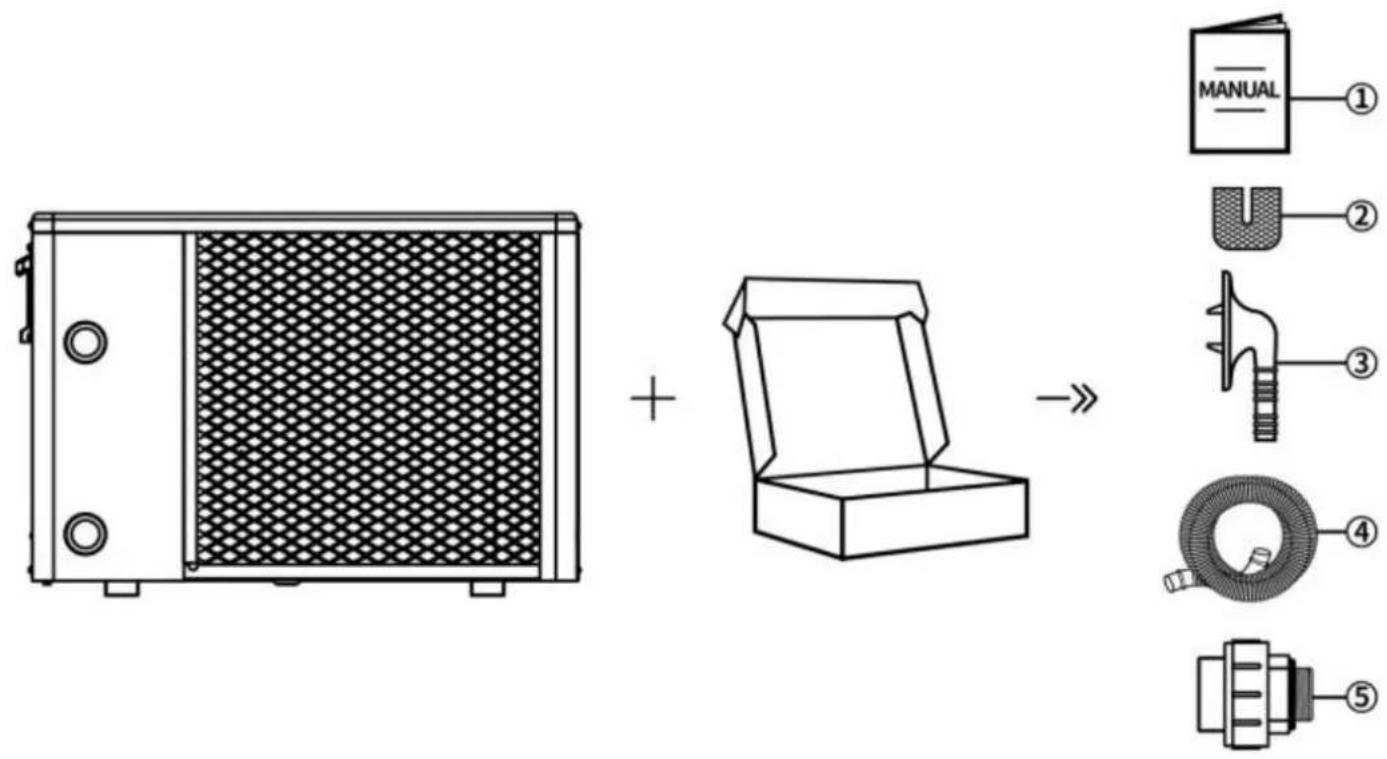
| NO. | Components | Quantity | NO. | Components | Quantity |
| 1 | User Manual | 1 | 4 | Drain Pipe | 2 |
| 2 | Rubber Blanket | 4 | 5 | Water Pipe Joint | 2 |
| 3 | Drain Connector | 2 |
2.2.Dimensions of the Unit
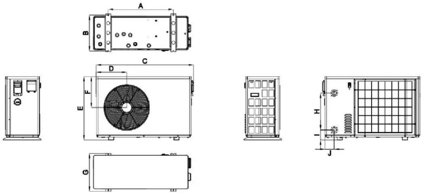
Dimension Unit: (mm)
| Model | A | B | C | D | E | F | G | H | I | J |
| VBPYCE-70 | 549 | 339 | 910 | 304 | 618 | 307 | 360 | 320 | 98 | 80 |
| VBPYCE-110 | ||||||||||
| VBPYCE-150 | 671 | 370 | 1002 | 314 | 654 | 320 | 391 | 380 | 103 | 95 |
| VBPYCE-210 | 720 | 423 | 1192 | 358 | 775 | 407 | 447 | 470 | 108 | 126 |
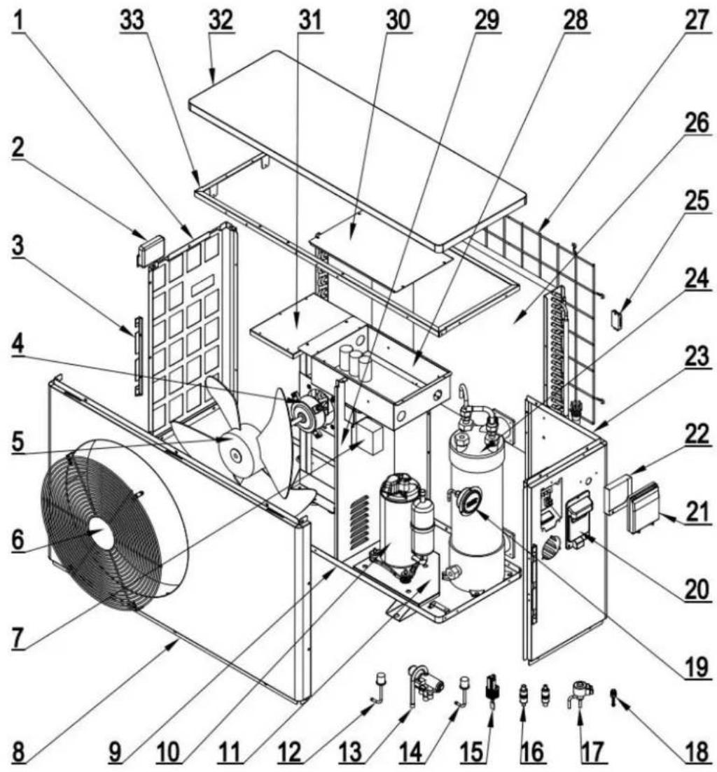
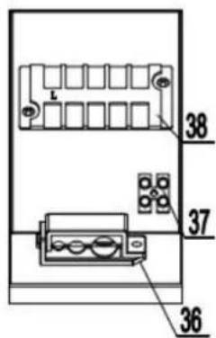
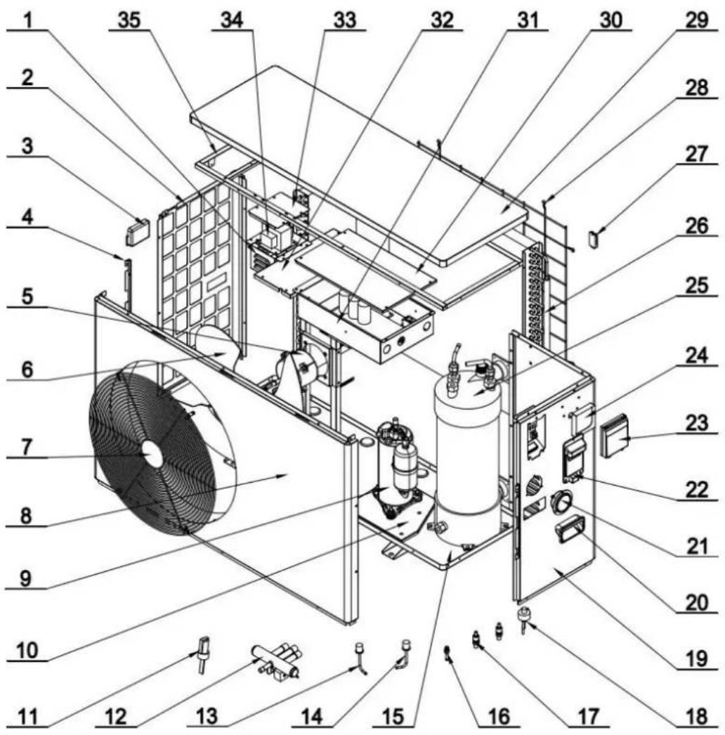
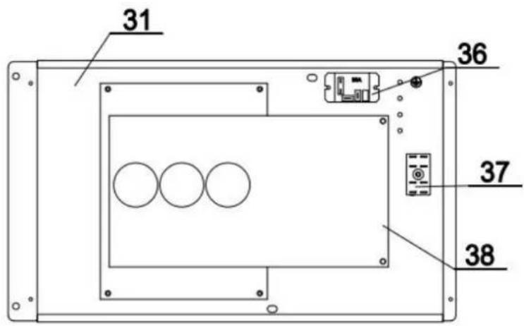
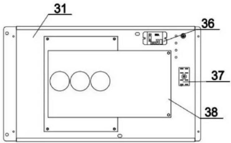
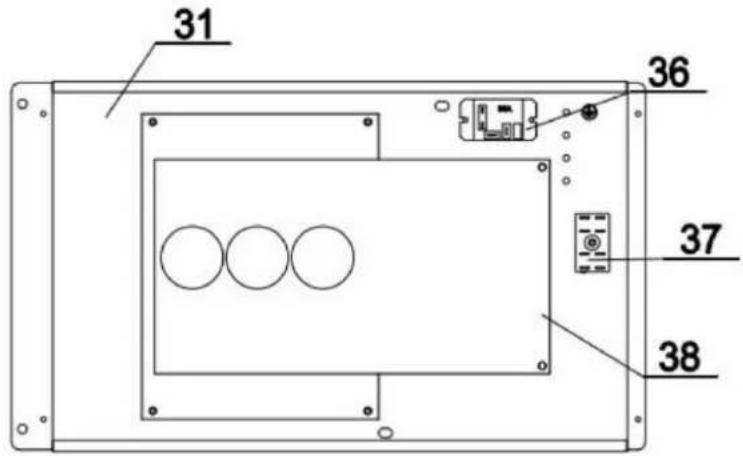
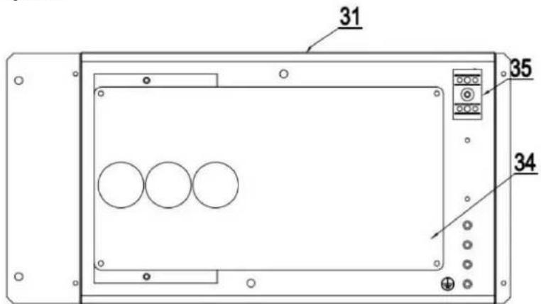
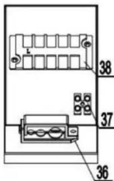
2.3.Main Parts of the Unit
2.3.1.VBPYCE-70,VBPYCE-110
① Sheet metal and other structures
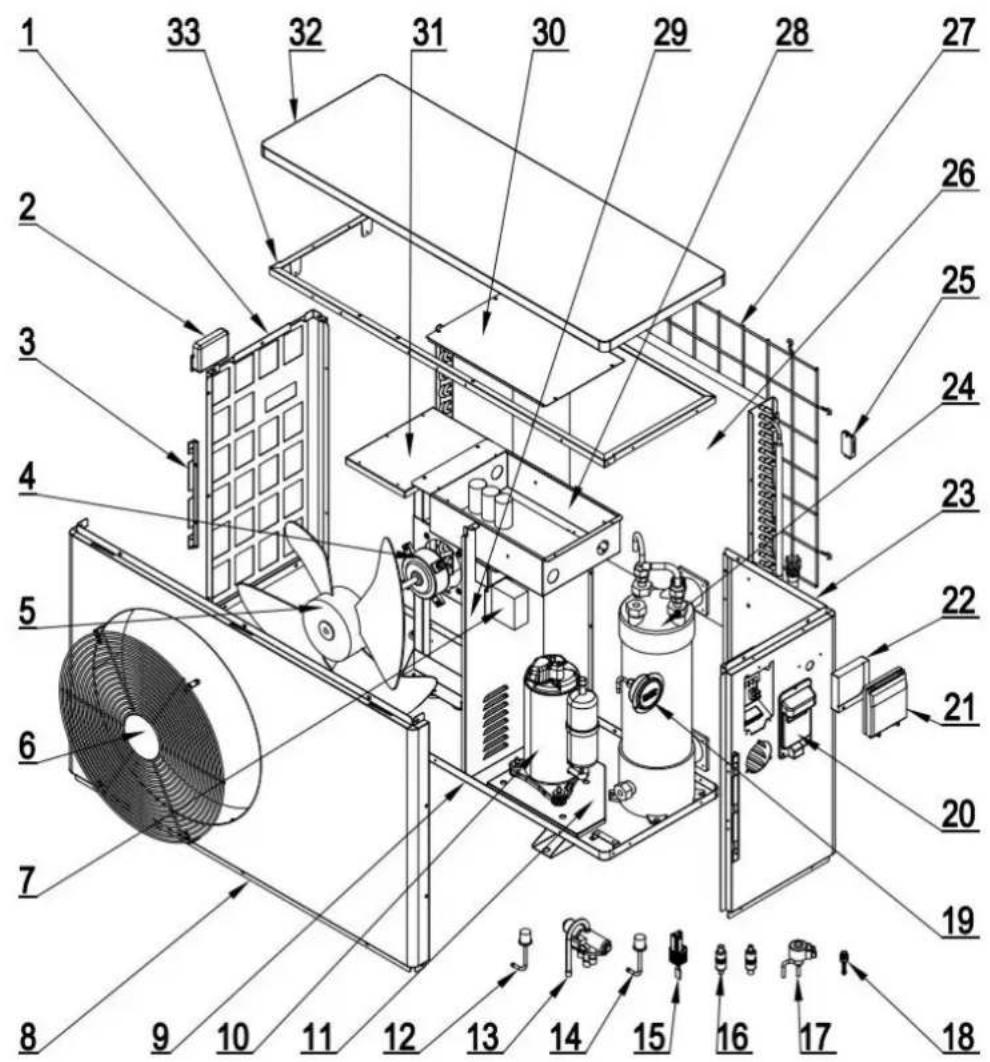
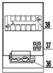
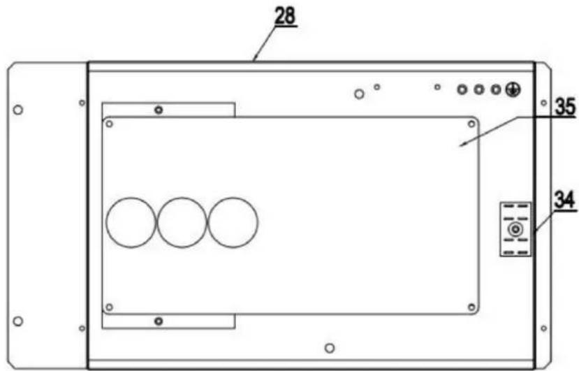
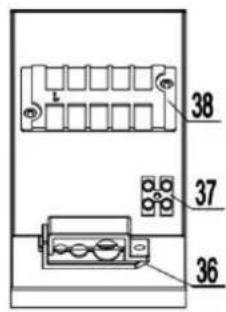
② Electrical System
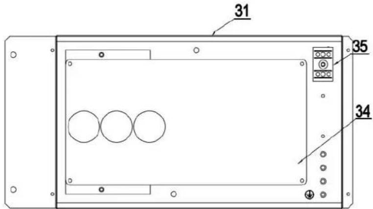
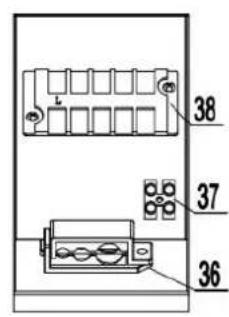
| 1 | Left Plate | 14 | EEV | 27 | Evaporator Component |
| 2 | Left Handle | 15 | Water Flow Switch | 28 | Reactor |
| 3 | Side Fixing Plate | 16 | Low Pressure Switch | 29 | Roof Assembly |
| 4 | Motor | 17 | Filter | 30 | Electrical Box Cover |
| 5 | Fan Blade | 18 | Needle Valve | 31 | Electrical Box Components |
| 6 | Fan Guard | 19 | Pressure Gauge | 32 | Motor Support |
| 7 | Median Septum | 20 | Right Plate | 33 | Inner Frame Components |
| 8 | Front Plate | 21 | Wired Controller Box | 34 | Main Board |
| 9 | Chassis | 22 | Wired Controller | 35 | 2U Terminal |
| 10 | Suspension Chassis | 23 | Right Handle | 36 | Cable Clip |
| 11 | Compressor | 24 | Titanium Heat Exchanger | 37 | 2-Position Terminal Board |
| 12 | High Pressure Switch | 25 | Ambient Temp Sensor Holder | 38 | 5-Position Terminal Board |
| 13 | 4-Way Valve | 26 | Back Net |
2.3.2.VBPYCE-150
① Sheet metal and other structures
② Electrical System

| 1 | Left Plate | 14 | Low Pressure Switch | 27 | Back Net |
| 2 | Left Handle | 15 | Water Flow Switch | 28 | Electrical Box Components |
| 3 | Side Fixing Plate | 16 | Filter | 29 | Median Septum |
| 4 | Motor | 17 | EEV | 30 | Electrical Box Cover |
| 5 | Fan Blade | 18 | Needle Valve | 31 | Motor Support |
| 6 | Fan Guard | 19 | Pressure Gauge | 32 | Roof Assembly |
| 7 | Reactor | 20 | Right Handle | 33 | Inner Frame Components |
| 8 | Front Plate | 21 | Wired Controller Box | 34 | 2U Terminal |
| 9 | Chassis | 22 | Wired Controller | 35 | Main Board |
| 10 | Compressor | 23 | Right Plate | 36 | Cable Clip |
| 11 | Suspension Chassis | 24 | Titanium Heat Exchanger | 37 | 2-Position Terminal Board |
| 12 | High Pressure Switch | 25 | Ambient Temp Sensor Holder | 38 | 5-Position Terminal Board |
| 13 | 4-Way Valve | 26 | Evaporator Component |
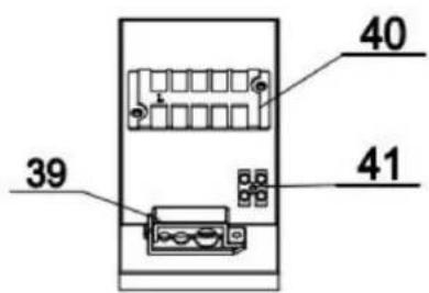
2.3.3.VBPYCE-210
① Sheet metal and other structures
② Electrical System
| 1 | Reactor Box | 15 | Chassis | 29 | Roof |
| 2 | Left Net | 16 | Needle Valve | 30 | Electrical Box Cover |
| 3 | Left Handle | 17 | Filter | 31 | Electrical Box Components |
| 4 | Side Fixing Plates | 18 | EEV | 32 | Motor Support |
| 5 | Motor | 19 | Right Plate | 33 | Reactor Box Cover |
| 6 | Fan Blades | 20 | Right Handle | 34 | Reactor |
| 7 | Fan Guard | 21 | Pressure Gauge | 35 | Inner Frame Components |
| 8 | Front Plate | 22 | Handle | 36 | Relay |
| 9 | Compressor | 23 | Wired Controller Box | 37 | 2U Terminal |
| 10 | Suspension Chassis | 24 | Wired Controller | 38 | Main Control Board |
| 11 | Water Flow Switch | 25 | Titanium Heat Exchanger | 39 | 5-Position Terminal Board |
| 12 | 4-Way Valve | 26 | Evaporator | 40 | 2-Position Terminal Board |
| 13 | High Pressure Switch | 27 | Ambient Temp Sensor Holder | 41 | Cable Clip |
| 14 | Low Pressure Switch | 28 | Fin Net |
2.4. Operation Range
- Heating Mode
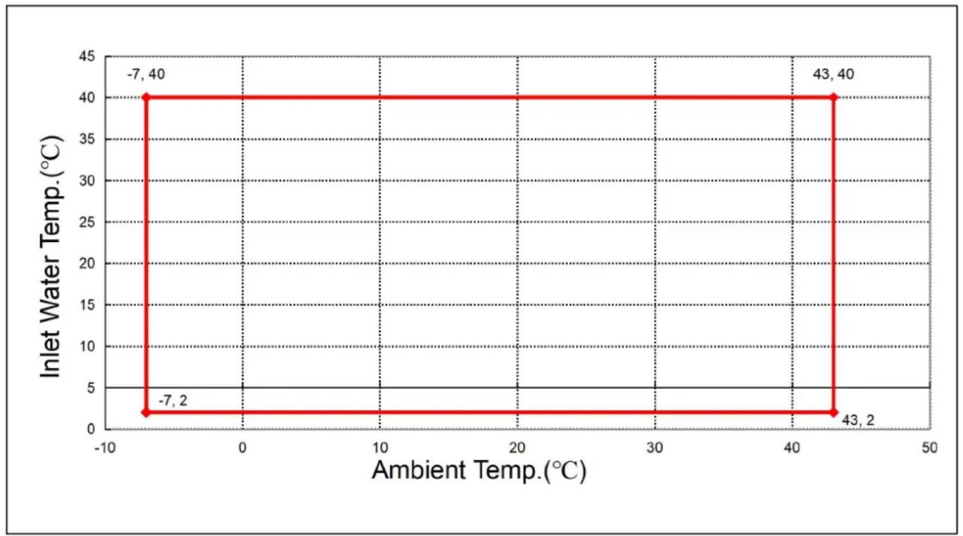
line
| Ambient Temp.(°C) | Inlet Water Temp.(°C) | | ----------------- | --------------------- | | -7 | 2 | | -7 | 40 | | 43 | 2 | | 43 | 40 |2.5.Parameter of the Unit
| Model:NF- | 70PR3-ID | 110PR3-ID | 150PR3-ID | 210PR3-ID |
| Advised Pool Size (m3) | 15~30 | 25~50 | 30~60 | 45~80 |
| [Heating] Ambient Temperature: (DB/WB) 27°C/24.3°C; Water Inlet/Outlet Temperature: 26°C/28°C. | ||||
| Heating capacity(kW) | 7.02 | 11.50 | 15.25 | 21.32 |
| Power input (kW) | 0.99 | 1.62 | 2.33 | 2.98 |
| COP | 7.09 | 7.11 | 6.55 | 7.15 |
| [Heating] Ambient Temperature: (DB/WB) 15°C/12°C; Water Inlet Temperature: 26°C. | ||||
| Heating capacity(kW) | 5.62 | 8.02 | 11.22 | 15.46 |
| Power input(kW) | 1.13 | 1.59 | 2.33 | 3.09 |
| COP | 4.98 | 5.03 | 4.83 | 5.00 |
| [Cooling ] Ambient Temperature: (DB/WB)°C/35 Water Inlet/Outlet Temperature: °C 28°C. | ||||
| Cooling Capacity (kW) | 3.91 | 6.25 | 8.54 | 11.58 |
| Power Input (kW) | 0.89 | 1.48 | 2.04 | 2.68 |
| EER | 4.39 | 4.22 | 4.19 | 4.32 |
| Max Power Input (kW) | 1.68 | 2.81 | 3.82 | 5.05 |
| Max Current (A) | 7.30 | 12.23 | 16.60 | 21.94 |
| Power Supply | 220V-240V~/50Hz | |||
| Heating Water Temp. Range(°C) | 9-40 | |||
| Cooling Water Temp. Range(°C) | 8-28 | |||
| Operating range(°C) | -10~43 | |||
| Refrigerant | R32 | |||
| Compressor Brand/Type | Mitsubishi | |||
| Manometer | Yes(Optional) | |||
| Gas Control | EEV | |||
| Water Heat Exchanger | Titanium Heat Exchanger | |||
| Water Pipe Connection | 1-1/2" | |||
| Water Pressure Drop (kPa) | 15 | 14 | 17 | 19 |
| Water Proof Level | IPX4 | IPX4 | IPX4 | IPX4 |
| Water Flow (m3/h) | 3.1 | 4.9 | 6.6 | 9.1 |
| Noise [dB(A)] at 1m | 40~52 | 43~53 | 44~54 | 45~56 |
| Net Weight(kg) | 44.5 | 48.5 | 55.5 | 76.0 |
| Net Dimensions(L*W*H)mm | 910×355×620 | 1000×400×660 | 1080×455×775 | |
3. INSTALLATION AND CONNECTION

WARNING:The heat pump must be installed by a professional team. The users are
qualified to install by themselves, otherwise the heat pump might be damaged and risky for safety.
This section is provided for information purposes only and must be checked and adapted if according to the actual installation conditions.
3.1. Transportation
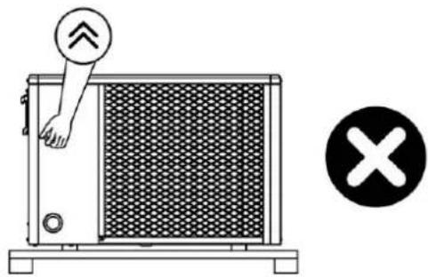
- When storing or moving the heat pump, the heat pump should be at the upright position
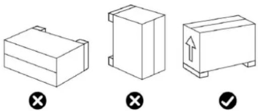
- When moving the heat pump, do not lift the water union since the titanium heat exchange heat pump will be damaged.
natural_image
Diagram of a heat exchanger with directional arrow and checkmark symbols (no text or labels)3.2. Notice Before Installation
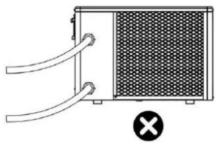
- The inlet and outlet water unions can't bear the weight of soft pipes. The heat pump must be connected with hard pipes!
natural_image
Diagram of a heat exchanger or cooling unit with pipes and a mesh chamber, marked with a black X symbol (no text or labels)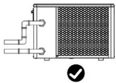
natural_image
Technical line drawing of a heat exchanger or cooling unit with pipes and a mesh chamber, plus a checkmark icon (no text or symbols)- In order to guarantee the heating efficiency, the water pipe length should be ≤10m between pool and the heat pump.
3.
3.3.Installation Instruction
3.3.1 Pre-requirements
Equipment necessary for the installation of your heat pump:
①Power supply cable suitable for the unit's power requirements.
②A By-Pass kit and an assembly of PVC tubing suitable for your installation as well as stripper, PVC adhesive and sandpaper.
③A set of wall plugs and expansion screws suitable to attach the unit to your support.
④We recommend that you connect the unit to your installation by means of flexible PVC pipes in order to reduce the transmission of vibrations.
⑤Suitable fastening studs may be used to raise the unit.
3.3.2 Heat Pump Installation
①The frame must be fixed by bolts (M10) to concrete foundation or brackets. The concrete foundation must be solid; the bracket must be strong enough and anti-rust treated;
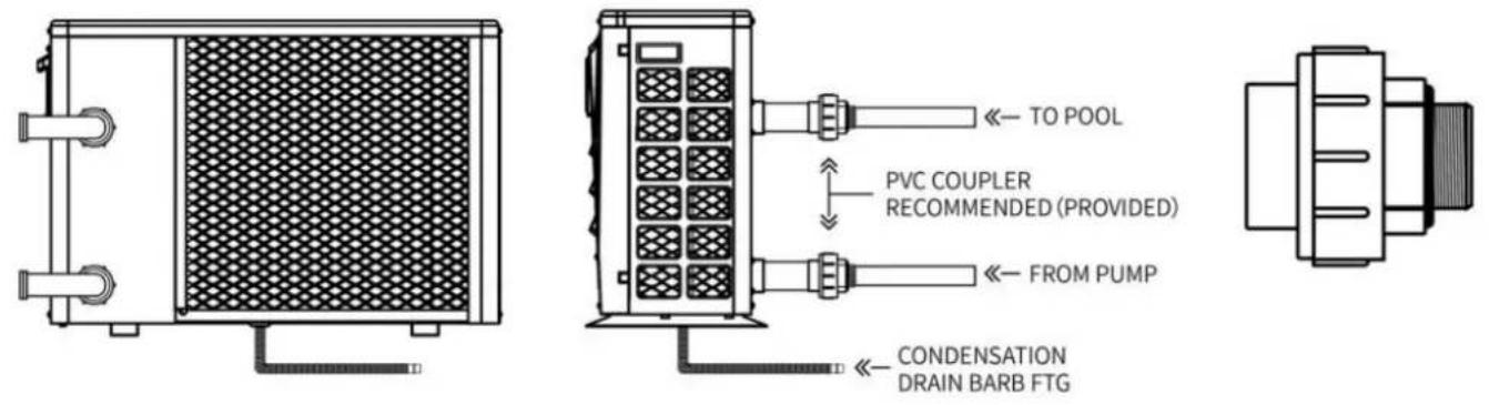
②The heat pump needs a water pump (Supplied by the user). The recommended pump specification-flux: refer to Technical Parameter, Max. lift ≥10m;
③When the heat pump is running, there will be condensation water discharged from the bottle please pay attention to it. Please insert the drainage tube(accessory) into the hole and clip connect a pipe to drain off the condensation water.Install the heat pump, raising it at least solid water-resistant pads, then connect the drainage pipe to the opening located under the
3.3.3 Location and Space
Please comply with the following rules concerning the choice of heat pump location.
①The unit's future location must be easily accessible for convenient operation and maintenance
②It must be installed on the ground, fixed ideally on a level concrete floor. Ensure that the floor is sufficiently stable and can support the weight of the unit.
③A water drainage device must be provided close to the unit in order to protect the area where it is installed.
④If necessary, the unit may be raised by using suitable mounting pads designed to support its weight.
⑤Check that the unit is properly ventilated, that the air outlet is not facing the windows of neighbouring buildings and that the exhaust air cannot return. In addition, provide sufficient space around the unit for servicing and maintenance operations.
⑥The unit must not be installed in an area exposed to oil, flammable gases, corrosive prod sulphur compounds or close to high frequency equipment.
⑦To prevent mud splashes, do not install the unit near a road or track.
⑧To avoid causing nuisance to neighbors, make sure the unit is installed so that it is positioned towards the area that is least sensitive to noise.
⑨Keep the unit as much as possible out of the reach of children.
⑩Installation space:
Unit: mm
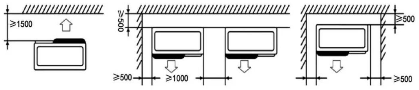
Do not put anything less than one meter in front of the heat pump.
Leave 500 mm of empty space on the sides and back of the heat pump and free ventilation. Do not leave any obstacles above or in front of the device!
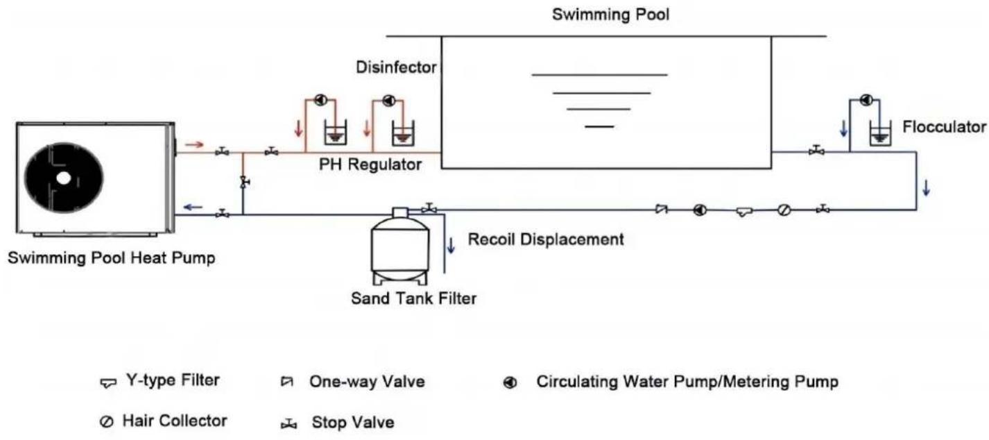
3.3.4 Installation Layout
Notice: The filter must be cleaned regularly to ensure that water in the system is clean and blocking of filter. It is necessary that drainage valve is fixed on the lower water pipe. If the running during winter months, please disconnect power supply and let out drain water from
through drainage valve. If ambient temperature of running unit is below 0^ C, please keep water pump running.
The installation diagram is shown in the following figure:
flowchart
graph LR
    A["Y-type Filter"] --> B["Swimming Pool Heat Pump"]
    C["One-way Valve"] --> D["PH Regulator"]
    E["Circulating Water Pump/Metering Pump"] --> F["Swimming Pool"]
    G["Hair Collector"] --> H["Sand Tank Filter"]
    I["Stop Valve"] --> J["Flocculator"]
    K["Disinfector"] --> L["Recoil Displacement"]
    M["Water Splitter"] --> N["Recoil Displacement"]
    O["Water Splitter"] --> P["Recoil Displacement"]
| No. | Item | Quantity | No. | Item | Quantity |
| 1 | Swimming Pump Heat Pump | 1 | 7 | PH Regulator | 1 |
| 2 | Y-Type Filter | 1 | 8 | Sand Tank Filter | 1 |
| 3 | One-Way Valve | 1 | 9 | Flocculator | 1 |
| 4 | Circulating Water Pump | 1 | 10 | Disinfector | 1 |
| 5 | Hair Collector | 1 | 11 | Metering Pump | 3 |
| 6 | Stop Valve | 7 |
3.3.5 Electrical Installation
To function safely and maintain the integrity of your electrical system, the unit must be conr general electricity supply in accordance with the following regulations:
①Upstream, the general electricity supply must be protected by a 30mA differential switch.
②The heat pump must be connected to a suitable D-curve circuit breaker in accordance with current standards and regulations in the country where the system is installed.
③The electricity supply cable must be adapted to match the unit's rated power and the length of wiring required by the installation. The cable must be suitable for outdoor use.
④For a three-phase system, it is essential to connect the phases in the correct sequence. If phases are inverted, the heat pump's compressor will not work.
⑤In places open to the public, it is mandatory to install an emergency stop button close to the heat pump.
| Model | Power Supply Wires | ||
| Electricity Supply | Cable Diameter | Specification | |
| VBPYCE-70 | 220-240V~50Hz/60Hz | 3G 1.5mm ^2 | 14AWG |
| VBPYCE-110 | 220-240V~50Hz/60Hz | 3G 1.5mm ^2 | 14AWG |
| VBPYCE-150 | 220-240V~50Hz/60Hz | 3G 2.5mm ^2 | 12AWG |
| VBPYCE-210 | 220-240V~50Hz/60Hz | 3G 2.5mm ^2 | 12AWG |
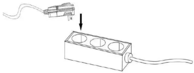
3.3.6 Electrical Connection
WARNING: Power supply of ice bath chiller must be disconnected before any operation.
Please comply with the following instructions to connect the ice bath chiller.
Step 1: Prepare a socket
Step 2: Insert the plug into the socket as the following picture shows
Ensure that all electrical equipment is properly grounded.
natural_image
Line drawing of a plug inserted into a rectangular socket with three circular holes, showing a downward arrow (no text or symbols)Plug Power Supply
220-240V\~/50Hz
3.4.Trial After Installation

WARNING: Please check all the wiring carefully before turning on the heat pump.
3.4.1. Inspection Before Trial Running
Before running test, confirm below items and write √ in block;
| □ | Correct unit installation |
| □ | Power supply voltage is the same as unit rated voltage |
| □ | Correct piping and wiring |
| □ | Air inlet & outlet port of unit is unblocked |
| □ | Drainage and venting is unblocked and no water leaking |
| □ | Leakage protector is working |
| □ | Piping insulation is working |
| □ | Ground wire is connected correctly |
Step 1: Running test can begin after completing all installation;
Step 2: All wiring and piping should be connected well and carefully checked, then fill water before power is switched on;
Step 3: Emptying all air within pipes and water tank, press "on-off" button on control panel to
unit at setting temperature;
Step 4: Items need to be checked during running test:
①During the first running, unit current is normal or not;
②Each function button on control panel is normal or not;
③Display screen is normal or not;
④Are there any leakage in the whole heating circulation system;
⑤Condensate drain is normal or not;
⑥Are there any abnormal sound or vibration during running?
4. Controller Operation Guidance
4.1.Display
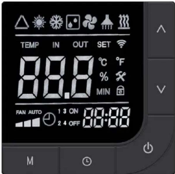
Basic Icons
| Icon | Meaning | Icon | Meaning |
 | Automatic Mode |  | Blower Icon |
 | Heating Mode |  | Fault Icon |
 | Refrigeration Mode |  | Lock Key Indicator |
 | Defrost Symbol |  | Electric Heating Symbol |
 | Silent Mode | 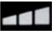 | powerful Mode |
 | Intelligent Mode |  | WiFi Icon |
4.2.Key Instructions
 | Power | Short press: toggle power on/off status, exit the current interface, return main interface |
| Press and hold for 3 seconds: lock/unlock the button | ||
 | Up | Short press: Enter the set temperature state in the power-on state and the current value |
| Press and hold for 3 seconds: manually turn on/off the electric heating | ||
 | Down | Short press: Enter the temperature setting state when the device is tu and decrease the current value |
| Press and hold for 3 seconds: Enter the crew parameter status q | ||
 | Mode | Short press: Press the mode key when the device is turned on to sw automatic/cooling/heating modes |
| Press and hold for 3 seconds: Switch frequency mode, mute/intelligent/ mode | ||
 | Alarm | Short press: Enter clock settings |
| Press and hold for 3 seconds: Enter the scheduled on/off setting in |
4.3. Combination Key Instruction
| Button operation | Operation duration | Function Description |
 | 3 seconds | Enter forced defrost under the main interface |
 | 3 seconds | Switch between Fahrenheit and Celsius under the r interface |
 | 5 seconds | Enter password input state |
 | 3 seconds | Restore factory settings |
 | 3 seconds | Enter default network configuration |
 | 3 seconds | Enter compatible network configuration |
4.4.Operation Function Instruction
| NO. | Item | Operation Way |
| 1 | Key Lock | Long press the " key on the main interface for 3 second lock/unlock the button. |
| 2 | On/Off | In unlock state, tap on the main interface" " to switch between status; in shutdown state, display water temperature, unit, and o startup state, display water temperature, unit, clock, operating mo frequency mode |
| 3 | Temperature Setting | Press the " or " button while the device is powered enter the temperature setting interface. The displayed set tempe will blink. Modify the current set temperature by pressing the " " button. If no operation is made within 30 seconds for the button is briefly pressed, the current set temperature will be sa exited. |
| 4 | Mode Switch | While powered on, press the " " key to switch the operating automatic → cooling → heating. |
| 5 | Frequency Mode Switch | While powered on, press and hold the " " key for 3 seconds the operating frequency mode, mute → intelligent → strong n |
| 6 | Clock Setting | Press the " button to enter the clock setting state. The position blinks first, indicating that the current hour value can be using the " and " keys. Pressing the " key once increas the hour by 1, and pressing the " " key once decreases the you hold down the " " key or the " " key for a long time, th automatically increase or decrease. After setting the hour value, the " key again; at this point, the minute position blinks, inc that the current minute value can be adjusted using the " "" " After setting the minute value, press the " " key again to e |
| 7 | Timer On/Off Setting | Press and hold the " " key for 3 seconds to enter the timer Enter the timer selection, at this time, the "timer on 1" clock "I and you can set the hour by using the " " and " " keys; pr "key again to switch to the clock "minute", and you can minute by using the " " and " " keys; press the " " key aga switch to the "timer off 1" setting: the clock "hour" blinks, and the hour by using the " " and " " keys; press the " " key ag switch to the clock "minute", and you can set the minute by "and "keys; set other time periods in the same way, a time periods for timer settings;Press to exit or confirm.Return to the main interface, the current set timing period w displayed;Cancel the timing setting:Under the scheduled startup setting, pr the key can cancel/enable the scheduled startup function |
| 8 | Forced Defrost | Long press the " key and " " key for 3 seconds while in startup mode to enter the forced defrost mode. When entering the defrost icon will flash and display " ". |
| 9 | Switch Temperature Units | When the device is turned off, long press the " " and " " o main interface for 3 seconds to switch between Celsius and Fa |
| 10 | Status Query | Under the main interface, press and hold the " " key for 3 se enter the crew status parameter query. Use the " " and " " k browse parameters, and press the " " key to exit parameter qu the status query interface, if there is no key operation for cons seconds, the status query interface will automatically exit and re the main interface. |
| 11 | Restore Factory Parameters | While in shutdown state, press and hold the " " key + " " "key + key for 3 seconds to restore the factory settings line control. At this time, the buzzer will sound twice continuous parameter values will revert to the default settings. |
4.5.Trouble Shooting
Fault code and solution
When a fault occurs, the main interface flashes the corresponding fault code, and when null codes appear, they flash alternately.
| Error Code | Error Description | Remark |
| E03 | Water flow protection | |
| E04 | Winter anti-freezing | |
| E05 | High pressure fault | |
| E06 | Low pressure fault | |
| E09 | Communication fault between main board and display | |
| E10 | Communication failure of the variable frequency module (Alarm the communication between the outer board and the driver b disconnected) | |
| E12 | High exhaust temperature protection | |
| E15 | Water Inlet Temperature fault | |
| E16 | External pipe temperature fault | |
| E18 | Exhaust Temperature fault | |
| E19 | Direct current fan failure | |
| E20 | Variable frequency module abnormal protection | |
| E21 | Environmental temperature failure | |
| E22 | DC fan 2 failure | |
| E23 | Low refrigerant outlet temperature protection | |
| E27 | Leakage temperature fault | |
| E28 | CT Overcurrent Protection | |
| E29 | Return Air Temperature Fault | |
| E32 | Overheat protection of heating water outflow temperature/Protec against excessive difference in Inlet and outlet water tempera | |
| E33 | Outdoor coil high temperature protection | |
| E42 | Internal tube temperature failure |
E20 fault will simultaneously display the following fault numbers, switching fault codes every 3 seconds; fault numbers 1 to 128 are displayed first.
When fault numbers 1 to 128 do not occur, fault numbers 257 to 384 will be displayed. If faults of equal priority occur simultaneously, the fault numbers will be added together. For e> fault numbers 16 and 32 occur simultaneously, 48 will be displayed.
| Code | Name | Description | Processing Opinion |
| 1 | IPM overcurrent | IPM module issue | Replace the variable frequenc module |
| 2 | Press machine synchronization anomaly | Press machine failure | Replace Press Machine |
| 4 | Reserved | -- | -- |
| 8 | Press machine phase failure | Press machine wiring broken, poor contact | Check the press input line |
| 16 | Low DC bus voltage | Low input voltage, PFC modu failure | Check input voltage, replace module |
| 32 | DC bus voltage hi | Input voltage too high, PFC module failure | Replace the variable frequenc module |
| 64 | Excessive heat sin temperature | Host fan failure, air duct block | Check the fan, air duct |
| 128 | Heat sink temperature fault | Blower fan sensor short circuit open circuit fault | Replace the variable frequenc module |
| 257 | Communication failure | The frequency conversion modu has not received the comman from the main controller | Check the communication connections of the main cont and variable frequency module |
| 258 | AC input phase missing | Input phase missing (valid fo three-phase module) | Check input line |
| 260 | AC input overcurrent | Input three-phase imbalance (valid for three-phase module) | Check the input three-phase phase voltage |
| 264 | Low AC input voltage | Input voltage too low | Check input voltage |
| 272 | High-pressure failure | High-pressure failure (reserved) | |
| 288 | Overheating IPM temperature | Host fan failure, air duct block | Check the fan, air duct |
| 320 | Excessive peak current of press machine | The current of the compressor too high, the driver and the p are not matched | Replace the inverter module |
| 384 | Overtemperature of PFC module | Overheating of PFC module | Check the PFC module |
5.MAINTENANCE AND WINTERZING
5.1.Maintenance

WARNING: Before undertaking maintenance work on the unit, ensure that you have
disconnected the electrical power supply.
Cleaning
a. The heat pump's casing must be cleaned with a damp cloth. The use of detergents or of
household products could damage the surface of the casing and affect its properties.
b. The evaporator at the rear of the heat pump must be carefully cleaned with a vacuum cl soft brush attachment.
Annual maintenance
The following operations must be undertaken by a qualified person at least once a year.
a. Carry out safety checks.
b. Check the integrity of the electrical wiring.
c. Check the earthing connections.
d.Monitor the state of the pressure gauge and the presence of refrigerant.
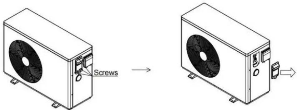
5.2.Disassembly Guidelines
Tools:
①Phillips screwdriver
②Wrench
③Flat-blade screwdriver
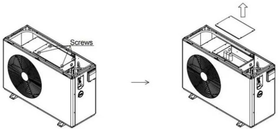
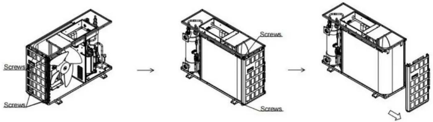
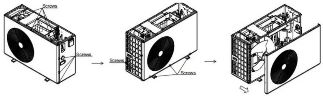
5.2.1 VBPYCE-70, VBPYCE-110
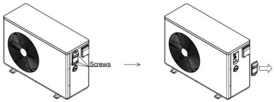
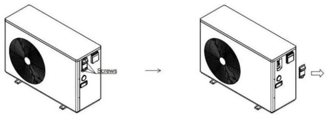
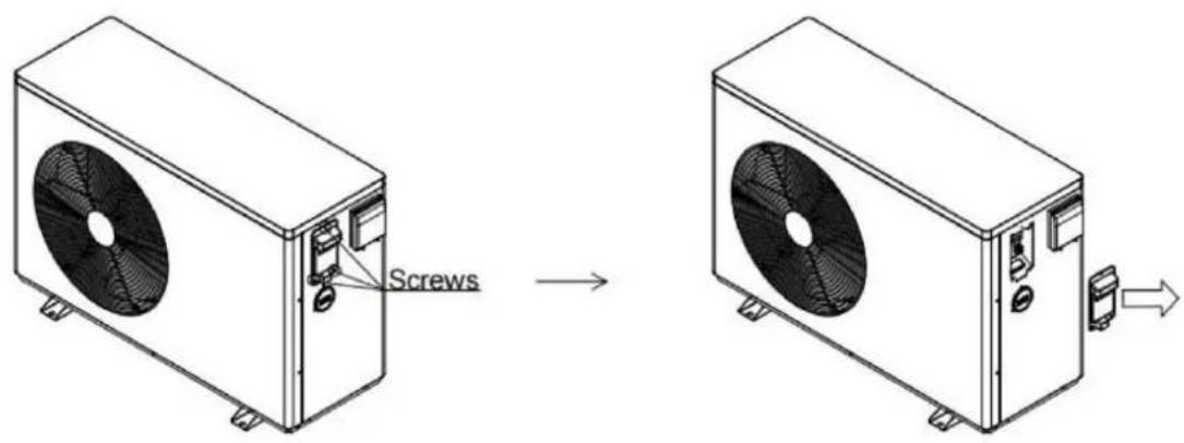
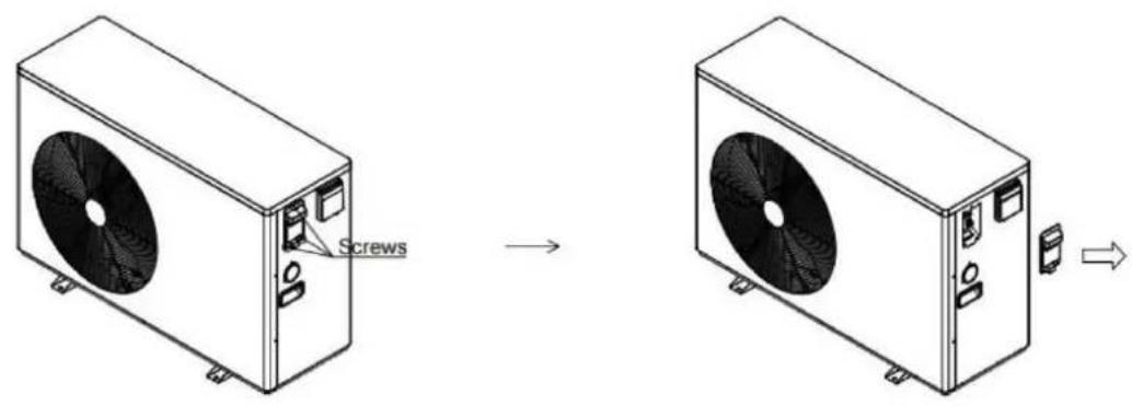
Step 1: Remove the terminal box cover
①Remove the screws on the terminal box cover
②Take out the junction box cover towards the arrow
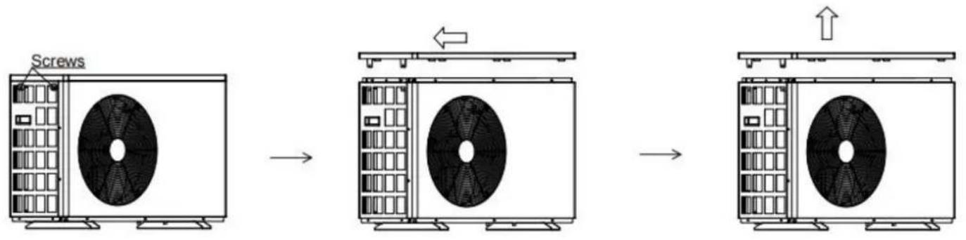
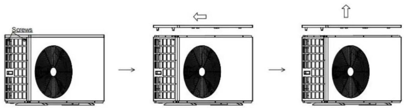
Step 2: Remove the top cover
①Remove the top cover screw
②Push the top cover in the direction of the arrow
③Take out the top cover towards the arrow
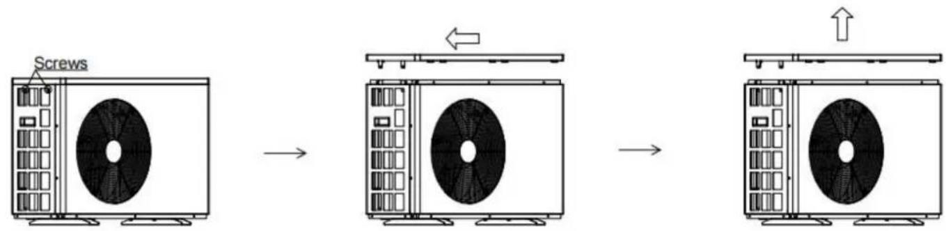
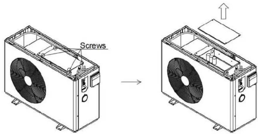
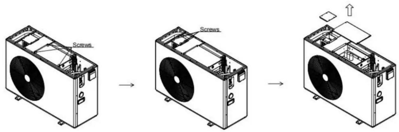
Step 3: Remove the electrical box cover
①Remove the screws on the electrical box cover
②Take out the electrical box cover in the direction of the arrow
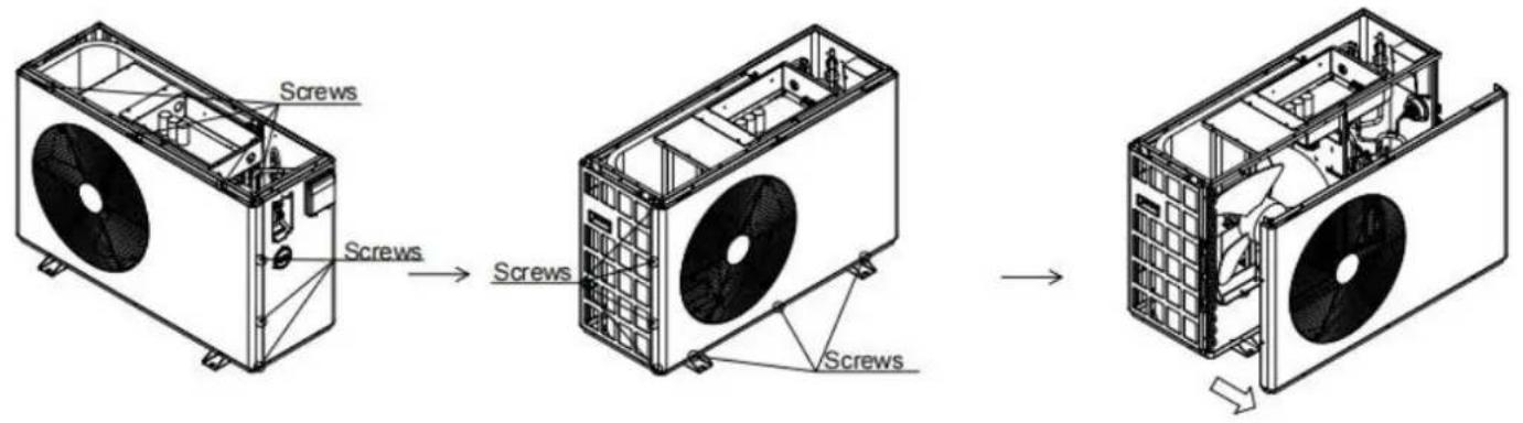
Step 4: Remove the front panel
①Remove the screws from the front panel
②Take out the front panel in the direction of the arrow
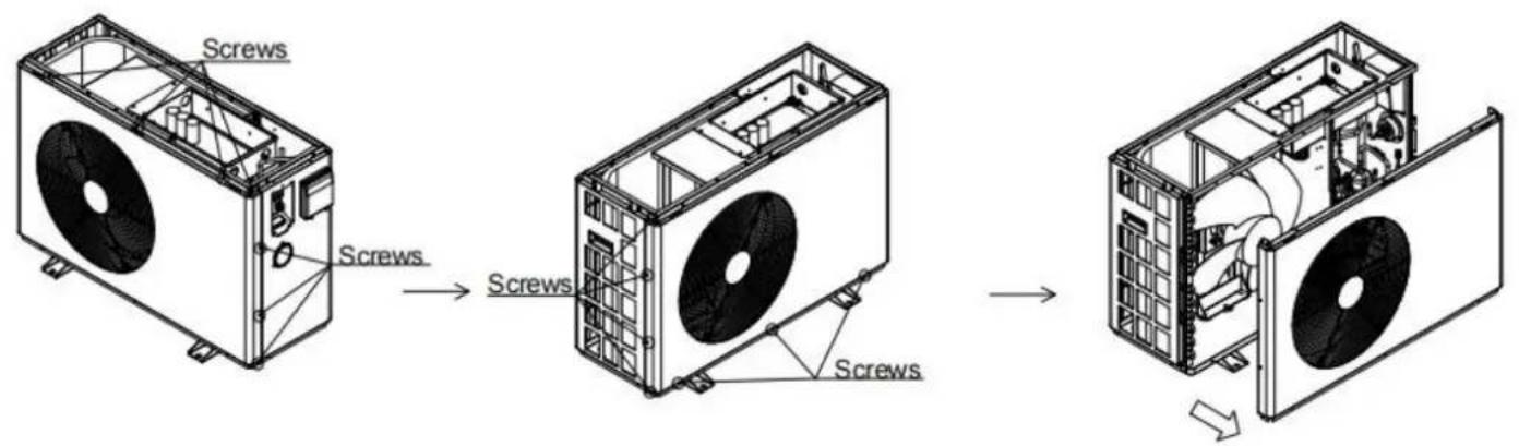
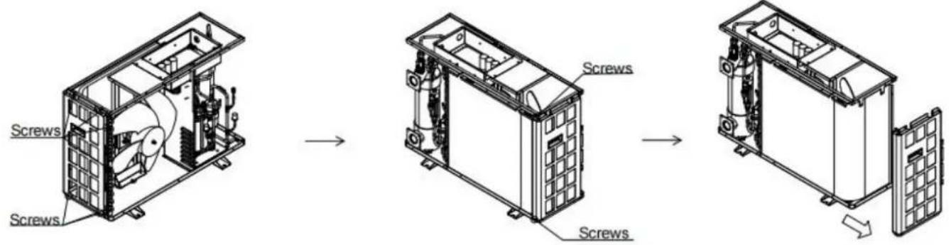
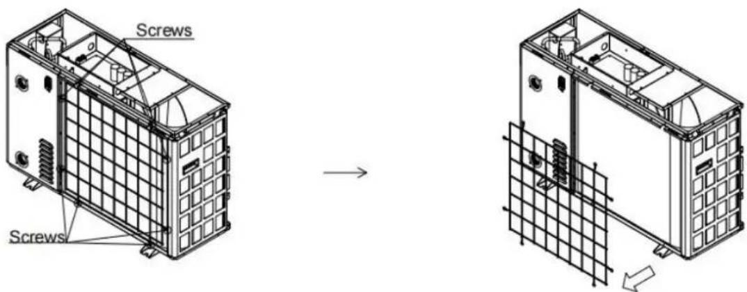
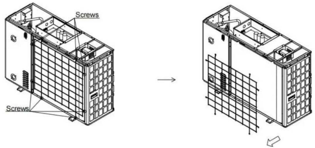
Step 5: Remove the rear cover
①Remove the screws holding the rear cover in place
②Pull the rear cover out of the way, following the arrow direction
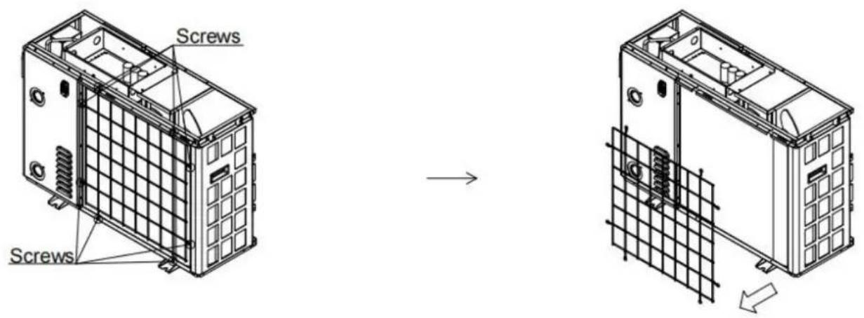
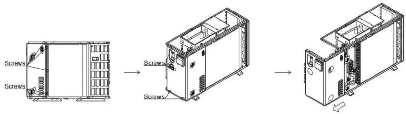
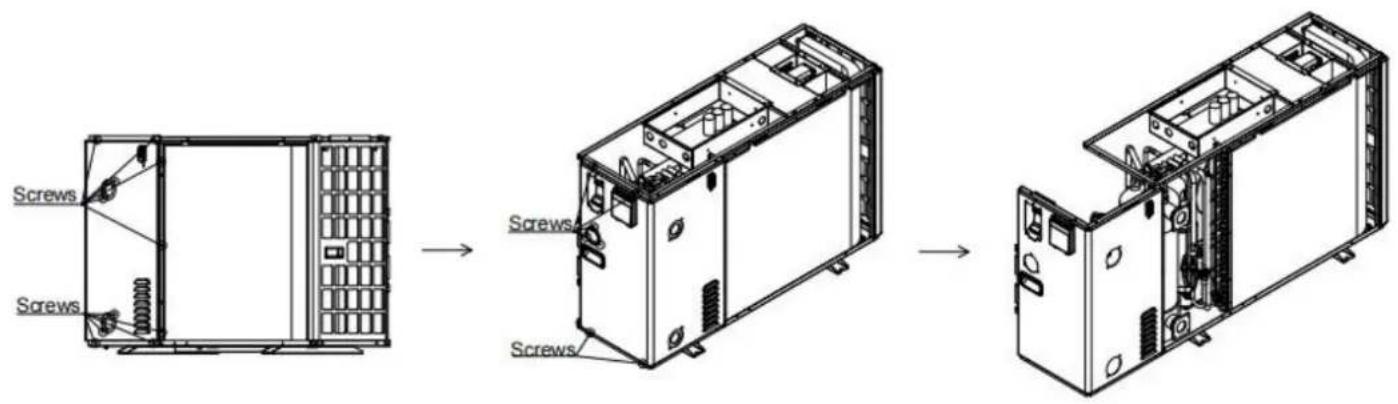
Step 6: Remove the right panel
①Remove the screw on the nozzle joint
②Remove the screws from the pressure gauge and right panel
③Take out the right board in the direction of the arrow
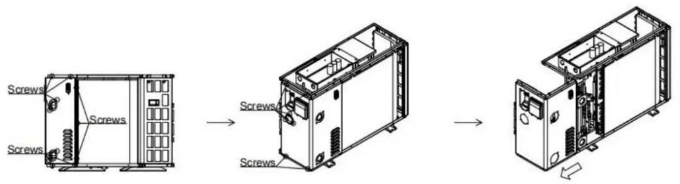
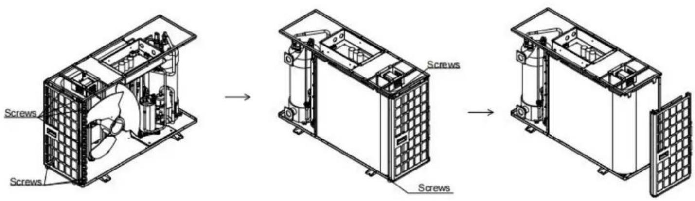
Step 7: Remove the left panel
①Remove the screws from the left panel
②Take out the left panel in the direction of the arrow
5.2.2 VBPYCE-150
Step 1: Remove the terminal box cover
①Remove the screws on the terminal box cover
②Take out the junction box cover towards the arrow
Step 2: Remove the top cover
①Remove the top cover screw
②Push the top cover in the direction of the arrow
③Take out the top cover towards the arrow
Step 3: Remove the electrical box cover
①Remove the screws on the electrical box cover
②Take out the electrical box cover in the direction of the arrow
Step 4: Remove the front panel
①Remove the screws from the front panel
②Take out the front panel in the direction of the arrow
Step 5: Remove the rear cover
①Remove the screws holding the rear cover in place
②Pull the rear cover out of the way, following the arrow direction
Step 6: Remove the right panel
①Remove the screw on the nozzle joint
②Remove the screws from the pressure gauge and right panel
③Take out the right board in the direction of the arrow
Step 7: Remove the left panel
①Remove the screws from the left panel
②Take out the left panel in the direction of the arrow
5.2.3 VBPYCE-210-PI
Step 1: Remove the terminal box cover
①Remove the screws on the terminal box cover
②Take out the junction box cover towards the arrow
Step 2: Remove the top cover
①Remove the top cover screw
②Push the top cover in the direction of the arrow
③Take out the top cover towards the arrow
Step 3: Remove the electrical box cover
①Remove the screws on the electrical box cover
②Remove the screws on the cover of the reactor box
③Take out the electrical box cover in the direction of the arrow
Step 4: Remove the front panel
①Remove the screws from the front panel
②Take out the front panel in the direction of the arrow
Step 5: Remove the rear cover
①Remove the screws holding the rear cover in place
②Pull the rear cover out of the way, following the arrow direction
Step 6: Remove the right panel
①Remove the screw on the nozzle joint
②Remove the screws from the pressure gauge and right panel
③Take out the right board in the direction of the arrow
Step 7: Remove the left panel
①Remove the screws from the left panel
②Take out the left panel in the direction of the arrow
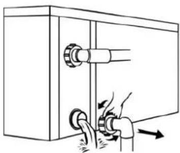
5.3 Winterizing

"CUT OFF" power supply of the heater before cleaning, examination and repairing
In winter season when you don't swim:
a. Cut off power supply to prevent any machine damage.
b. Drain water clear of the machine.
natural_image
Diagram of a mechanical valve assembly with two ports and directional arrows indicating flow or movement (no text or symbols)
!! Important:
Unscrew the water nozzle of inlet pipe to let the water flow out. When the water in machir winter season, the titanium heat exchanger may be damaged.
c. Cover the machine body when not in use.
VEVOR®
TOUGH TOOLS, HALF PRICE
Technical Support and E-Warranty Certificate
www.vevor.com/support
VEVOR®
TOUGH TOOLS, HALF PRICE
www.vevor.com/support
natural_image
Exterior view of a white industrial air conditioning unit with a black fan blade (no text or symbols visible)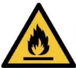

BESOIN D'AIDE? CONTACTEZ-NOUS!
Machine Translated by Google
Machine Translated by Google
équipement.
Machine Translated by Google
Machine Translated by Google
Machine Translated by Google
Machine Translated by Google
| VBPYCE-150 95 | 671 370 1002 | 314 654 | 320 391 | 380 | 103 720 | 423 1192 | 358 | 775 407 | 447 |
| VBPYCE-210 | 470 108 126 |
Système électrique

Machine Translated by Google
Système électrique

Système électrique
Machine Translated by Google
Machine Translated by Google
Machine Translated by Google
natural_image
Diagram of a heat exchanger or cooling unit with coiled tubing and a grid-patterned chamber, marked with a black X symbol (no text or labels)
natural_image
Technical diagram of a heat exchanger or cooling unit with pipes and a mesh chamber, marked by a checkmark (no text or symbols present)Machine Translated by Google
④ Circulating Water Pump/Metering Pump
∅ Hair Collector
Stop Valve
natural_image
Line drawing of a plug inserted into a rectangular socket with three circular holes, showing a downward arrow (no text or symbols)Machine Translated by Google
Machine Translated by Google
Machine Translated by Google
Machine Translated by Google
Machine Translated by Google
Machine Translated by Google
5.2.3 VBPYCE-210-PI
5.3 Hivernage
natural_image
Diagram of a hand pressing down on a pipe fitting into a cabinet (no text or symbols)
!! Important:
www.vevor.com/support
Pool-Wärmepumpe
Modell: VBPYCE-70/VBPYCE-110/VBPYCE-150/VBPYCE-210
natural_image
Exterior view of a white industrial air conditioning unit with a black fan blade (no text or symbols visible)

Machine Translated by Google
Ausrüstung.
Machine Translated by Google
Machine Translated by Google
Machine Translated by Google
Machine Translated by Google
| VBPYCE-150 95 | 671 3 | 70 | 1002 | 314 | 65 | 4 | 320 | 3 | 91 | 380 | 103 | 720 | 423 | 11 | 92 | 358 | 775 | 407 | 447 |
| VBPYCE-210 | 470 | 1 | 08 | 126 |
Machine Translated by Google
Machine Translated by Google
Machine Translated by Google
Machine Translated by Google
natural_image
Diagram of a heat exchanger or cooling unit with coiled pipes and a mesh panel, marked with a black X symbol (no text or labels)
natural_image
Technical diagram of a heat exchanger or cooling unit with pipes and a mesh chamber, marked by a checkmark (no text or symbols present)Machine Translated by Google
④ Circulating Water Pump/Metering Pump
∅ Hair Collector
Stop Valve
natural_image
Line drawing of a plug inserted into a rectangular block with three circular holes, showing a downward arrow (no text or symbols)Steckernetzteil
220-240V\~/50Hz
Machine Translated by Google
Machine Translated by Google
Machine Translated by Google
Machine Translated by Google
Machine Translated by Google
Machine Translated by Google
5.2.2 VBPYCE-150
5.2.3 VBPYCE-210-PI
5.3 Überwinterung

natural_image
Diagram of a hand operating a valve inside a cabinet with two buttons and directional arrows indicating motion (no text or symbols)
!! Wichtig:
www.vevor.com/support
natural_image
Exterior view of a white industrial air conditioning unit with a black fan blade (no text or symbols visible)

Machine Translated by Google
Machine Translated by Google
Machine Translated by Google
Machine Translated by Google
| VBPYCE-150 | 671 | 370 | 1002 | 314 | 654 | 320 | 391 | 380 | 103 | 720 | 423 | 1192 | 358 | 775 | 4957 |
| VBPYCE-210 | 447 | 470 | 108 | 126 |
Machine Translated by Google
Machine Translated by Google
Machine Translated by Google
Machine Translated by Google
natural_image
Diagram of a heat exchanger or cooling unit with coiled pipes and a mesh panel, marked with a black X symbol (no text or labels)
natural_image
Technical diagram of a heat exchanger or cooling unit with pipes and a mesh chamber, marked by a checkmark (no text or symbols present)Machine Translated by Google
④ Circulating Water Pump/Metering Pump
∅ Hair Collector
Stop Valve
natural_image
Line drawing of a plug-in socket connected to a rectangular block with three circular holes (no text or symbols)Machine Translated by Google
Icone di base
Machine Translated by Google
Machine Translated by Google
Machine Translated by Google
Machine Translated by Google
Machine Translated by Google
5.2.2 VBPYCE-150
5.2.3 VBPYCE-210-PI
5.3 Svernamento

natural_image
Diagram of a hand pressing down on a pipe fitting into a cabinet (no text or symbols)
!! Importante:
www.vevor.com/support
natural_image
Exterior view of a white industrial air conditioning unit with a black fan blade (no text or symbols visible)

Machine Translated by Google
Machine Translated by Google
equipo.
Machine Translated by Google
Machine Translated by Google
Machine Translated by Google
| VBPYCE-150 | 671 | 370 | 1002 | 314 | 654 | 320 | 391 | 380 | 103 | 720 | 423 | 1192 | 358 | 775 | 40795 |
| VBPYCE-210 | 447 | 470 | 108 | 126 |
Sistema eléctrico


Machine Translated by Google
Sistema eléctrico


Sistema eléctrico


Machine Translated by Google
Machine Translated by Google
Machine Translated by Google
natural_image
Diagram of a heat exchanger or cooling unit with coiled tubing and a grid-patterned chamber, marked with a black X symbol (no text or labels)
natural_image
Technical diagram of a heat exchanger or cooling unit with pipes and a mesh chamber, marked by a checkmark (no text or symbols present)Machine Translated by Google
④ Circulating Water Pump/Metering Pump
∅ Hair Collector
Stop Valve
natural_image
Line drawing of a plug inserted into a rectangular socket with three circular holes, showing a downward arrow (no text or symbols)Machine Translated by Google
Iconos básicos
Machine Translated by Google
Machine Translated by Google
Machine Translated by Google
Machine Translated by Google
Machine Translated by Google
5.2.2 VBPYCE-150
5.2.3 VBPYCE-210-PI
natural_image
Diagram of a mechanical assembly with two pipes and directional arrows indicating movement (no text or symbols)
!! Importante:
www.vevor.com/support
natural_image
Exterior view of a white industrial air conditioning unit with a black fan blade (no text or symbols visible)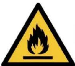

POTRZEBUJESZ POMOCY? SKONTAKTUJ SIĘ Z NAMI!
Machine Translated by Google
Machine Translated by Google
sprzę t.
Machine Translated by Google
dostę pny.
Procedury ładowania
Machine Translated by Google
Machine Translated by Google
Machine Translated by Google
Machine Translated by Google
| VBPYCE-150 95 | 671 | 370 | 1002 | 314 | 654 | 320 | 391 | 380 | 103 | 720 | 423 | 1192 | 358 | 775 | 407 |
| VBPYCE-210 | 447 | 470 | 108 | 126 |
Machine Translated by Google
Machine Translated by Google
Machine Translated by Google
Machine Translated by Google
natural_image
Diagram of a heat exchanger or cooling unit with coiled tubing and a grid-patterned chamber, marked with a black X symbol (no text or labels)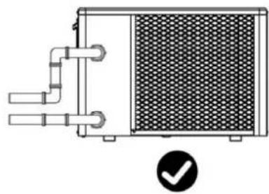
natural_image
Technical diagram of a heat exchanger or cooling unit with pipes and a mesh chamber, marked by a checkmark (no text or symbols present)Machine Translated by Google
④ Circulating Water Pump/Metering Pump
∅ Hair Collector
Stop Valve
natural_image
Line drawing of a plug inserted into a rectangular socket with three circular holes, showing a downward arrow (no text or symbols)Zasilacz wtykowy
220-240 V\~/50 Hz
Machine Translated by Google
Podstawowe ikony
Machine Translated by Google
Machine Translated by Google
Machine Translated by Google
Machine Translated by Google
Machine Translated by Google
5.2.2 VBPYCE-150
5.2.3 VBPYCE-210-PI
5.3 Zimowanie

natural_image
Diagram of a hand turning a valve into a cabinet with arrows indicating motion (no text or symbols)
!! Ważny:
www.vevor.com/support
Zwembad warmtepomp
Model: VBPYCE-70/VBPYCE-110/VBPYCE-150/VBPYCE-210
natural_image
Exterior view of a white industrial air conditioning unit with a black fan blade (no text or symbols visible)

HULP NODIG? NEEM CONTACT MET ONS OP!
Machine Translated by Google
Machine Translated by Google
Machine Translated by Google
Machine Translated by Google
Machine Translated by Google
| VBPYCE-150 95 | 671 | 370 | 1002 | 314 | 654 | 320 | 391 | 380 | 103 | 720 | 423 | 1192 | 358 | 775 | 407 |
| VBPYCE-210 | 447 | 470 | 108 | 126 |
ÿ Elektrisch systeem

Machine Translated by Google
ÿ Elektrisch systeem


ÿ Elektrisch systeem

| 1 | Reactordoos | 15 | Chassis | 29 | Dak |
| 2 | Linkernet | 16 | Naaldventiel | 30 | Elektrische doosdeksel |
| 3 | Linker handvat | 17 | Filter | 31 | Elektrische doos Componenten |
| 4 | Zijbevestigingsplaten | 18 | EEV | 32 | Motorondersteuning |
| 5 | Motor | 19 | Rechter plaat | 33 | Reactorkastdeksel |
| 6 | Ventilatorbladen | 20 | Rechter handvat | 34 | Reactor |
Machine Translated by Google
Machine Translated by Google
| Verwarmingsvermogen (kW) | 5,62 | 8,02 | 11.22 | 15.46 |
| Opgenomen vermogen (kW) | 1,13 | 1,59 | 2.33 | 3.09 |
| COP | 4,98 | 5,03 | 4.83 | 5,00 |
| [Koeling] Omgevingstemperatuur: (DB/WB) 35 /-; Waterinlaat-/uitlaattemperatuur: 30 /28 . | ||||
| Koelvermogen (kW) 8,54 Opgenomen | 3,91 vermogen (kW) | 2,04 | 6.25 | |
| 0,89 | 1.48 | 11.58 | ||
| 4.39 | 4.22 | 4.19 | 2.68 | |
| Maximaal opgenomen vermogen (kW) | 1.68 | 2.81 | 3,82 | 4.32 |
| Maximale stroom (A) | 7.30 | 12.23 | 16,60 | 5.05 |
| Voeding | 220V-240V~/50Hz | |||
| Verwarmingswatertemperatuurbereik ( ) | 9-40 | |||
| Koelwatertemperatuurbereik ( ) | 8-28 | |||
| Bedrijfsbereik ( ) | -10~43 | |||
| Koelmiddel | R32 | |||
| Compressor Merk/Type | Mitsubishi | |||
| Manometer | Ja (optioneel) | |||
| Gascontrole | EEV | |||
| Waterwarmtewisselaar | Titanium warmtewisselaar | |||
| Waterleidingaansluiting | 1-1/2" | |||
| Waterdrukverlies (kPa) | 15 | 14 | 17 | 19 |
| Waterdichtheidsniveau | IPX4 | IPX4 | IPX4 | IPX4 |
| Waterstroom (m3/u) | 3.1 | 4,9 | 6.6 | 9.1 |
| Geluid [dB(A)] op 1m | 40~52 | 43~53 | 44~54 | 45~56 |
| Nettogewicht (kg) | 44.5 | 48,5 | 55.5 | 76.0 |
| Netto afmetingen (L*B*H) mm | 910×355×620 | 1000×400×660 | 1080×455×775 | |
3. INSTALLATIE EN AANSLUITING

Machine Translated by Google
natural_image
Diagram of a heat exchanger or cooling unit with coiled pipes and a mesh panel, marked with a black X symbol (no text or labels)
natural_image
Technical diagram of a heat exchanger or cooling unit with pipes and a mesh chamber, marked by a checkmark (no text or symbols present)Machine Translated by Google
natural_image
Line drawing of a plug inserted into a rectangular socket with three circular holes, showing a downward arrow (no text or symbols)Stekkervoeding
220-240V\~/50Hz
Machine Translated by Google
Machine Translated by Google
Machine Translated by Google
Machine Translated by Google
Machine Translated by Google
Machine Translated by Google
5.2.2 VBPYCE-150
5.2.3 VBPYCE-210-PI
natural_image
Diagram of a hand pressing down on a pipe fitting into a cabinet (no text or symbols)
!! Belangrijk:
www.vevor.com/support
Poolvärmepump
Modell: VBPYCE-70/VBPYCE-110/VBPYCE-150/VBPYCE-210
natural_image
Exterior view of a white industrial air conditioning unit with a black fan (no text or symbols visible)

BEHÖVER HJÄLP? KONTAKTA OSS!
Machine Translated by Google
utrustning.
Machine Translated by Google
ÿ Elsystem

Machine Translated by Google
ÿ Elsystem

ÿ Elsystem


Machine Translated by Google
Machine Translated by Google
natural_image
Three technical line drawings of rectangular blocks with different orientations and mounting points, marked with X and ✓ symbols (no text or labels present)Machine Translated by Google
natural_image
Diagram of a heat exchanger with a hand pointing to its side panel and an X symbol indicating cancellation or rejection (no text or labels present)natural_image
Diagram of a heat exchanger or cooling unit with coiled pipes and a mesh panel, marked with an 'X' symbol (no text or labels present)
natural_image
Technical diagram of a heat exchanger or cooling unit with pipes and a mesh chamber, marked by a checkmark (no text or symbols present)④ Circulating Water Pump/Metering Pump
∅ Hair Collector
Stop Valve
3.3.5 Elinstallation
natural_image
Line drawing of a plug inserted into a rectangular block with three circular holes, showing a downward arrow (no text or symbols)3.4. Test after installation

VARNING: Kontrollera alla ledningar noggrant innan du slår på värmepumpen.
Machine Translated by Google
Machine Translated by Google
Machine Translated by Google
Machine Translated by Google
Machine Translated by Google
5.2.2 VBPYCE-150
Steg 1: Ta bort kopplingslådans lock yTa bort skruvarna på kopplingsboxens lock yTa ut kopplingsboxens lock mot pilen
Steg 2: Ta bort topplocket yTa
5.2.3 VBPYCE-210-PI
Steg 1: Ta bort kopplingslådans lock
ÿTa bort skruvarna på kopplingsboxens lock ÿTa
ut kopplingsboxens lock mot pilen
Steg 2: Ta bort topplocket yTa
bort topplockets skruv ÿ Skjut
topplocket i pilens riktning ÿTa ut topplocket mot pilen

Steg 5: Ta bort den bakre luckan
5.3 Vinterställ
natural_image
Diagram of a hand turning a valve into a cabinet with arrows indicating motion (no text or symbols)
!! Viktig: