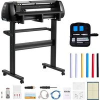
USER MANUAL SK-720L Vevor
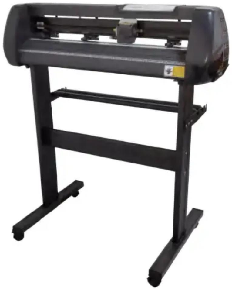
Cutting Plotter Machine
USER MANUAL
Have product questions? Need technical support? Please feel free to contact us: Technical Support and E-Warranty Certificate www.vevor.com/support
This is the original instruction. Please read all manual instructions carefully before operating. VEVOR reserves clear interpretation of our user manual. The appearance of the product shall be subject to the product you received. Please forgive us that we won't inform you again if there is any technology or software updates on our product.
CONTENTS
Precautions .... 1
Symbol Indication .... 1
Introduction for Main Parts 3
Technical Parameters 4
Accessory Box 5
Bracket Assembly Diagram 5
Control Buttons Description and Operation Instructions ......6
Product Assembly Steps 6
Software and Driver Installation 8
Connection of Software and Machine 11
App Operation Guide 13
Troubleshooting 15
Disposal 16
Attention 16
PRECAUTIONS
- Protective material must be removed before turning on the cutting plotter.
- Check the label on the backside of the plotter to confirm that the rated voltage required by the plotter matches the voltage of the power base.
- Firstly make sure that the power switch is off, then plug the power supply into a grounded power outlet.
- Please do not touch the power cord with wet hands to avoid electric shock.
- Use only the power cord and data cable provided by the product or the replacement approved by the manufacturer.
- Please do not drop metal objects and liquids into the machine to avoid malfunction.
- After shutting down, you must wait another 5 seconds to turn on the cutting plotter again, otherwise it will cause damage to the cutting plotter.
- In thunderstorms, turn the power switch to OFF and unplug the power cord.
- Please do not privately change the manufacturer's components. • Manufacturer reserves the right to change product specifications without prior notice.
- The manufacturer only bears the legal obligations of the product itself sold to the users and does not bear other losses caused by the malfunction of the products.
- Without our company's permit, no part of this manual can be copied or transmitted in any name.
- Do not drag the carriage by hand.
- If there is an abnormal sound after powering on the machine, please turn off the power immediately and contact the after-sales department for feedback.
SYMBOL INDICATION
To ensure that the plotter can be used correctly and avoid causing damage, users should follow the instructions below while operating.
1. Ensure Safe Use Methods
 | Warning | Improper operation can result in injury |
| Improper operation may cause damage to the machine |
 | Attention | Improper operation may result in personal injury or damage to other objects |
2. Symbol Description
 | Warning |
 | This symbol indicates that users need to pay close attention. The picture on the left means "Be careful of electric shock". |
 | Do not use a power supply that does not meet the rated voltage.Using an unqualified power supply can cause fire or electric shock. |
 | If the machine gives out smoke, smell, noise and other abnormal circumstances, please power off immediately.Continuing to use machine under these conditions could cause a fire or electric shock. |
 | Do not plug or remove the power plug when the power is on.Unplugging the power plug while the power is on will damage the machine. |
 | Ensure machine grounding.If not grounded, the machine will cause electrical shock or mechanical failures. |
 | Ensure machine grounding.Doing so will result in fire or electric shock, resulting in personal injury. |
 | Attention |
 | The machine can not penetrate into liquids, fall into metal objects, etc.These objects may cause fires. | 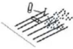 |
 | Do not destroy or replace the original power cord, and do not allow the power cord to be excessively bent, pulled, tied or pressed under heavy objects.Doing so could damage power supply, causing an electric shock or fire. | 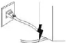 |
  | If the machine is not used for a long time, please unplug the power cord from the socket.Otherwise it could cause a fire.·When operating, do not put your hands on the roller.·This may cause injury. | 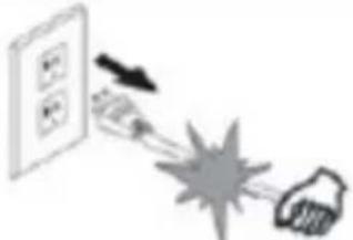  |
 | ·The machine should be placed on a stable surface.·Otherwise the machine will fall down and cause injury. |  |
 | ·When unplugging the power cord from the socket, the plug should be pulled, not the cable.·Pulling on the cable can cause electric shock or fire. | 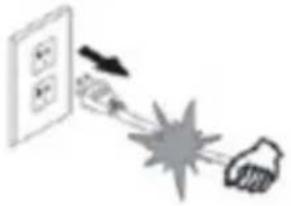 |
 | ·It is prohibited to use in thunderstorms and lightning weather.·To avoid lightning damage to the machine. | 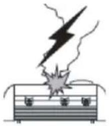 |
 | ·Before inserting the power plug, check whether the power supply voltage and power cable are normal.·Make sure you connect the device without exceptions. | 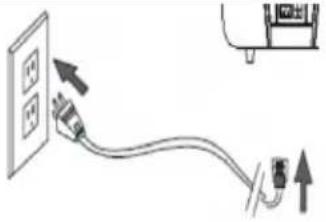 |
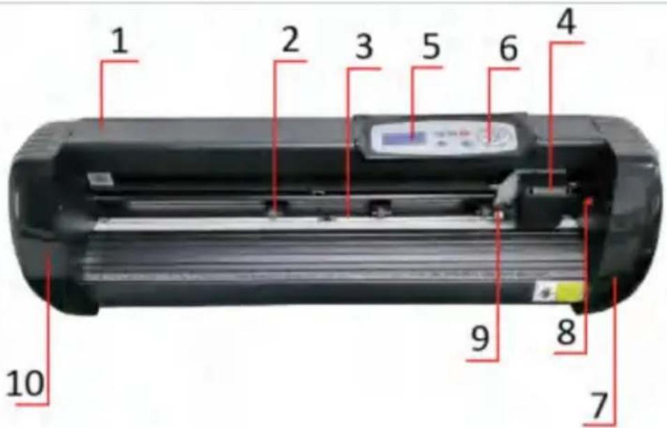
INTRODUCTION FOR MAIN PARTS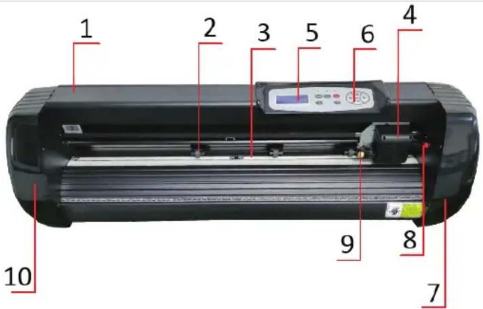
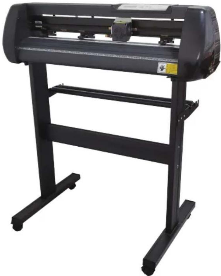
SK Model
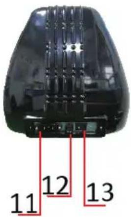
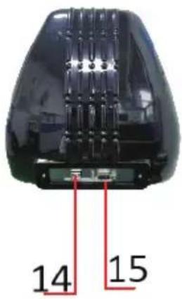
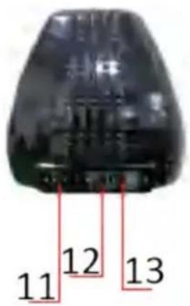
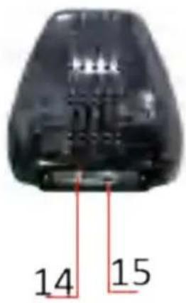
Left Side Right Side
- Cover for Rail Guide
- Pinch Roller Kit
- Roller for Feeding Paper
- Carriage
- Screen
- Buttons
- Right Cover
- Reset Switch
- Blade Clamp
- Left Cover
- Power Connection
- Fuse Holder
- Power Switch
- USB Port
- COM Port
TECHNICAL PARAMETERS
| Item\Model | SK-720L | SK-870L |
| Max Feeding Width | 720mm | 870mm |
| Max Cutting Width | 630mm | 780mm |
| Cutting Thickness | ≤1mm |
| Speed/Pressure | 20-800mm/s 20-500g |
| Buffer | 1-4M |
| LCD Display | CN/EN |
| Real-Time Speed Adjusting | Support |
| Interface | COM+USB +Bluetooth |
| Re-Cutting Function | Support |
| Re-Cutting Accuracy | 0.127mm |
| Resolution Ratio | 0.0245mm/step |
| Language Format | DMPL/HPGL |
| Voltage and Current | AC85-264V 2.5A |
| Package Size | 104*33*36CM | 119*33*36CM |
| Weight | 17KG | 19KG |
| Storage Environment and Working Environment | Temperature: +10±35°CRelative humidity: 30%-50% |
ACCESSORY BOX
| Item Quantity | | Unit |
| 1 | Cutting Plotter | 1 | Set |
| 2 | Power Supply Cable | 1 | Pc |
| 3 | Blade | 1 | Box |
| 4 | Blade Holder | 1 | Pc |
| 5 | Pen Holder | 1 | Pc |
| 6 | Ball Pen Core | 1 | Pc |
| 7 | COM Connection Cable | 1 | Pc |
| 8 | USB Cable | 1 | Pc |
| 9 | Spanner | 1 | Pc |
| 10 | USB Driver | 1 | Pc |
| 11 | Bracket Screws | 1 | Bag |
| To protect the machine, use only the accessories in this accessory box |
BRACKET ASSEMBLY DIAGRAM
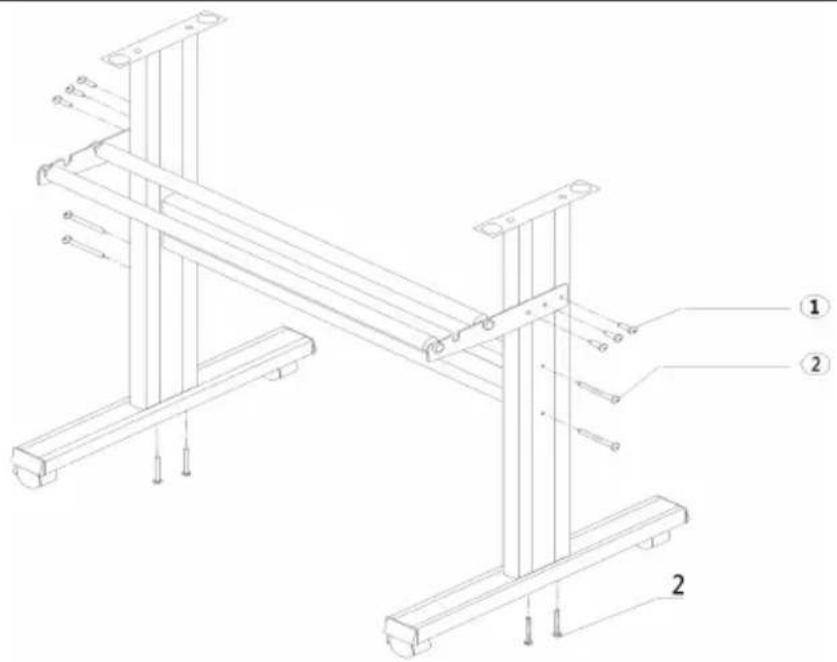
- Self-tapping screw 4*16, 6 pieces
- Self-tapping screw 4*40, 8 pieces
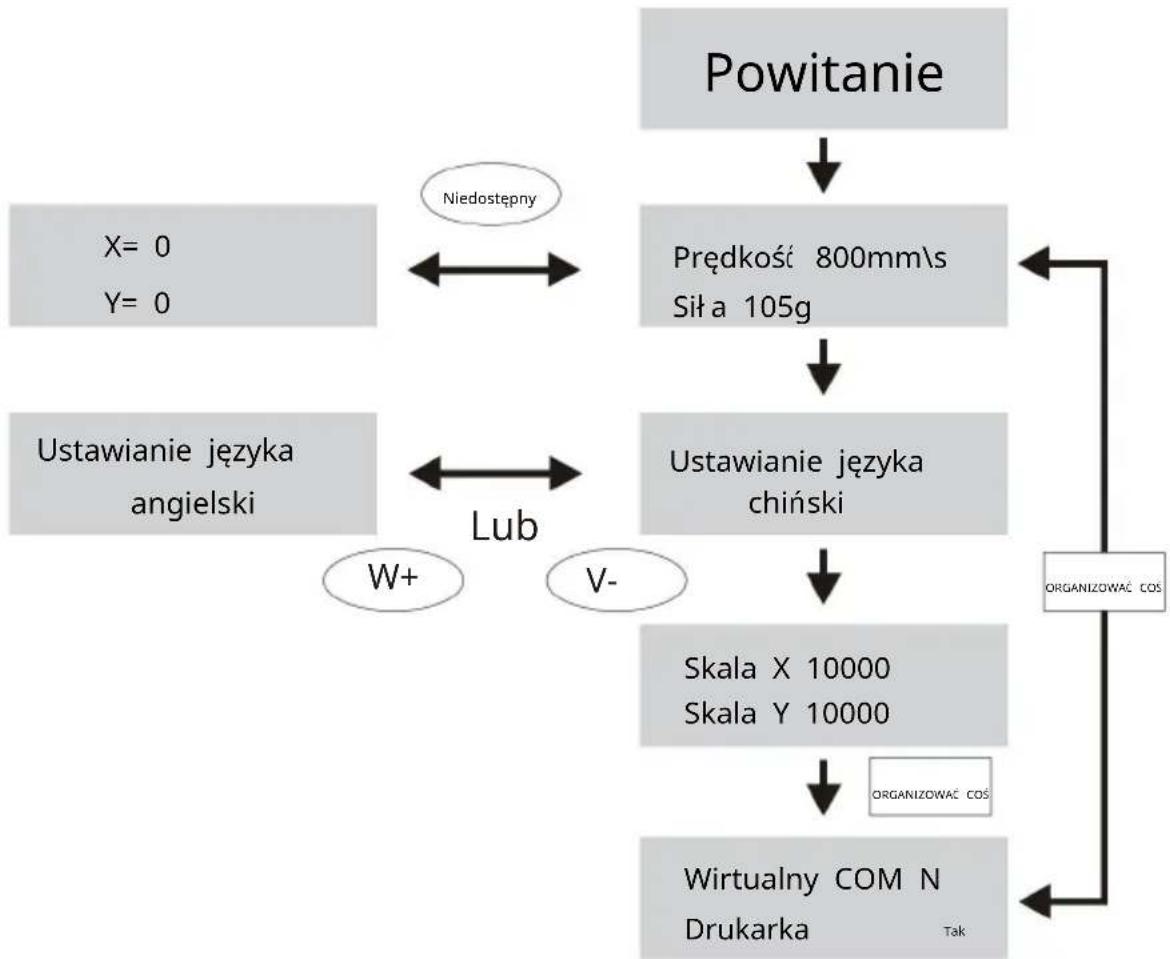
![graph TD A["Welcome"] --> B["Speed 800mm\s Force 105g"] B --> C["Setting Language Chinese"] C --> D["X scale 10000 Y scale 10000"] D --> E["SET UP"] E --> F["Virtual COM N Printer Y"] G["X= 0\nY= 0"] --> H["Setting Language English"] I["V+"] --> J["or"] K["V-"] --> J L["Offline"] --> B M["SET UP"] -…](/content/2026/04/736595/images/b4cb5ae93fa9716c495dd778639320edaee7b52fec6483c2b3131f36dd25b812.jpg)
PRODUCT ASSEMBLY STEPS
A: Place the machine on the stand. B: Connect the power supply.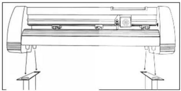
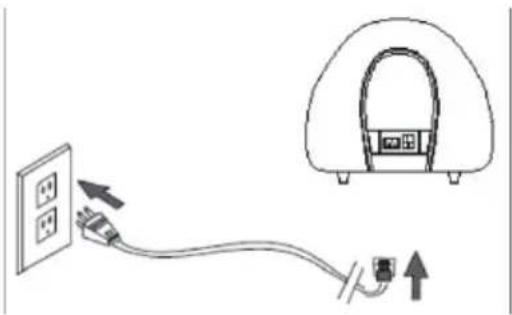
Before connecting the power supply, check the power supply voltage and the power cord. Under normal conditions, the power can be directly energized.
C: Blade assembly
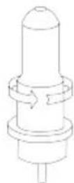
- Unscrew the cap from the Blade Carriage.
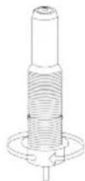
- Set the Brass Ring on the Blade Carriage to the fully down position.

- Remove the protective cover from a new blade.
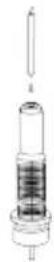
- Insert the blade into the top of the Blade Carriage.
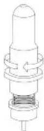
- Screw the cap back onto the Blade Carriage.
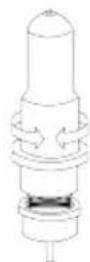
- Adjust the carriage cap until the blade is protruding approximately 1/64 of an inch.
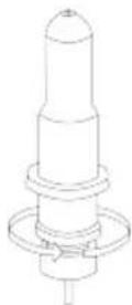
- Adjust the Brass Ring until it fits snugly against the Cap. This will help keep the cap in place during operation.
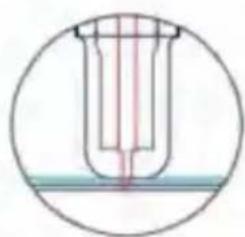
a. Assemble the blade into the holder, as shown below:
Appearance view Exploded view
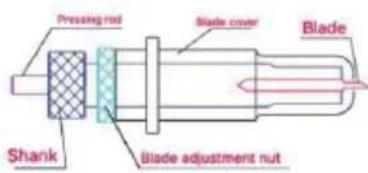
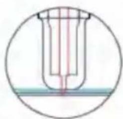
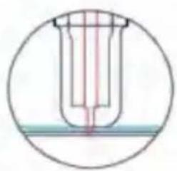
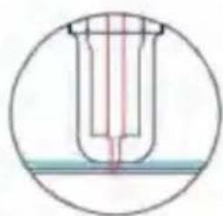
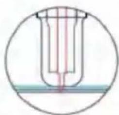
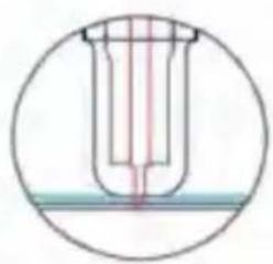
b. Loosen the blade adjustment nut and rotate the shank to adjust the length of the exposed blade tip. Determine the tip length according to the thickness of the material.

Correct Blade tip is too long Blade tip is too short
c. Press the pressing rod when you want to change the blade. Take out the blade when it is exposed.
d. Assemble the blade holder into the wagon:
- Loosen the fixed screw on the tool holder
- Put the blade holder into the tool holder
- Tighten and fix the blade holder when it arrives at the correct position
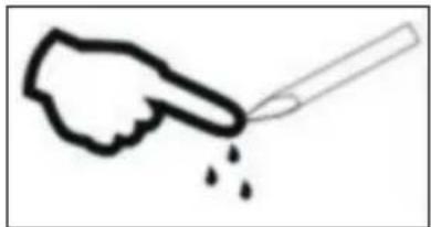
Tips:
Do not touch the blade tip with your finger; otherwise, your finger will be injured and the tip will become blunt.
d: Installation Procedure of Knife Holder
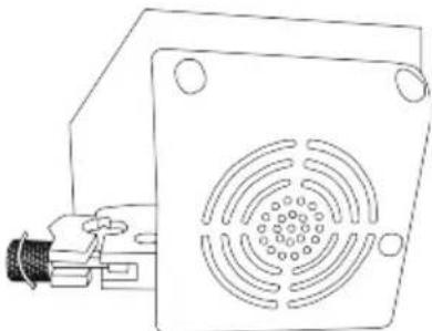
- Loosen the locking knob on the carriage arm.
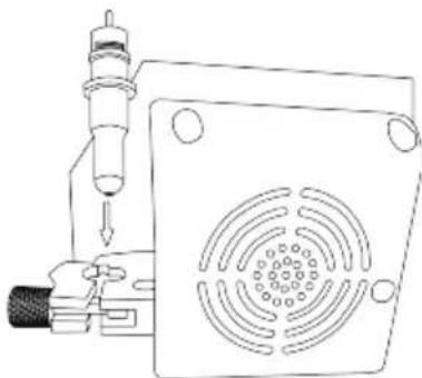
- Place the blade carriage into the carriage arm.
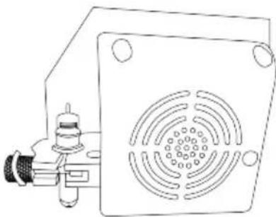
- Tighten the locking knob on the carriage arm.
Note: The cutting plotter can process soft coiled materials with a thickness of no more than 1 mm of adhesive backing. It is forbidden to process metal materials.
SOFTWARE AND DRIVER INSTALLATION
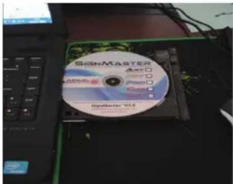
- Open the software box (pic 1), take the disk and put it into the CD optical drive (pic 2).
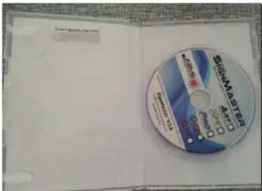
pic 1 pic 2
- Open the computer, double click or right click the optical drive to install the software (pic 3).
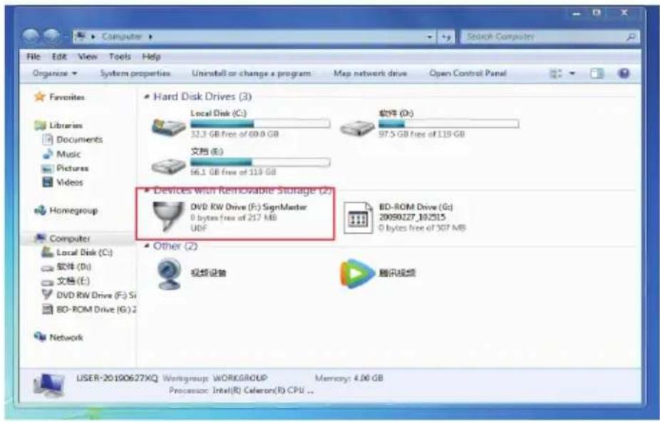
pic 3
- After opening the optical drive, click Install Software (pic 4).
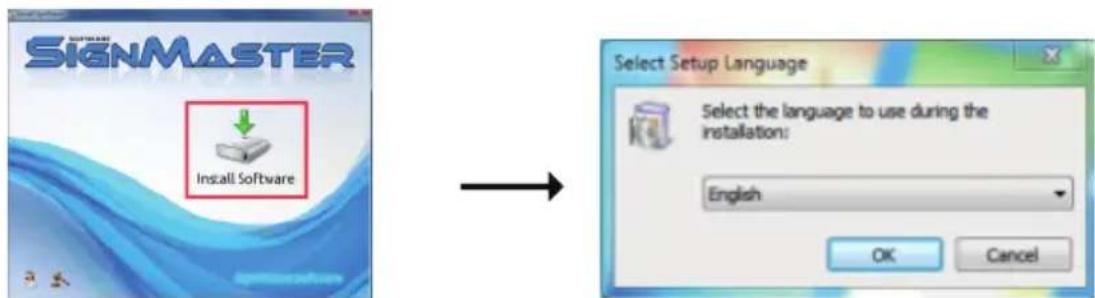
Click on the icon in the red box. Select the language (pic 4-1, pic 4-2).
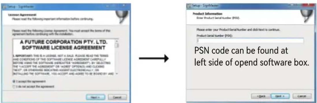
Enter the PSN code. Agree and click next (pic 4-3, pic 4-4).
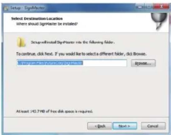
Default installation path, click next (pic 4-5).

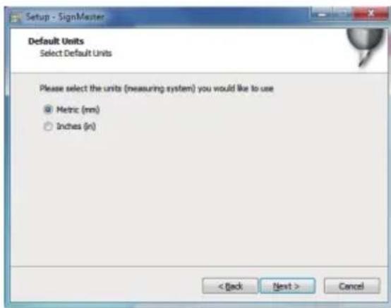
Select the unit (pic 4-6).
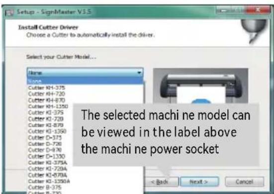
Select machine model (pic 4-7).

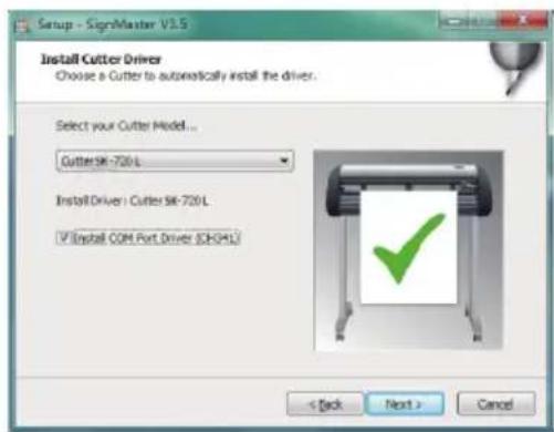
Please select install COM port driver (pic 4-8).
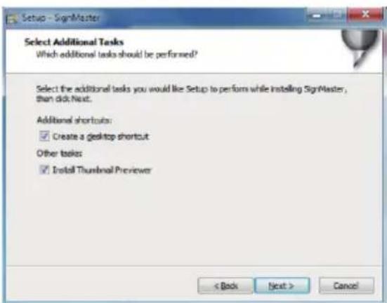
Next (pic 4-9).

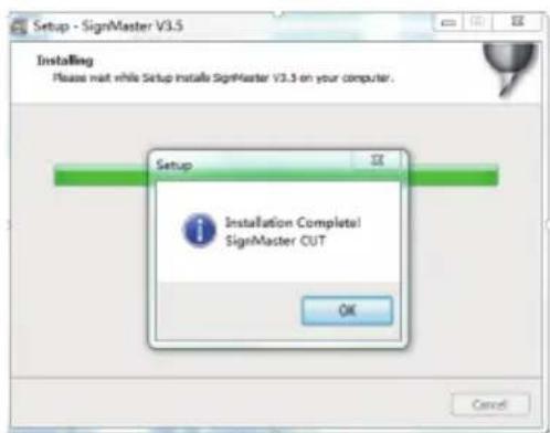
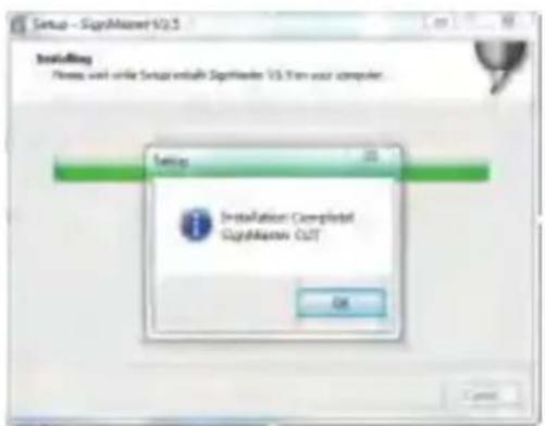
The installation is complete (pic 4-10).
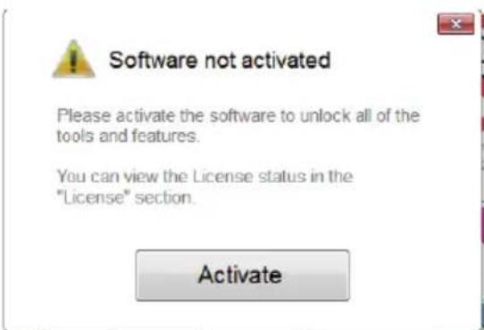
This activation window appears when you open the software (pic 4-11).

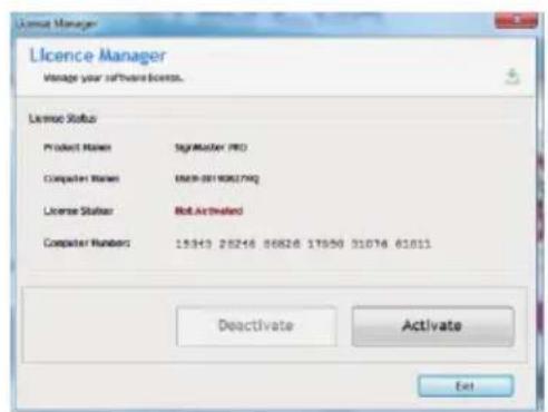
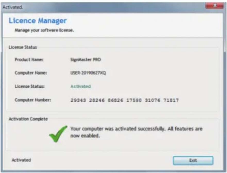
Click activate and enter your email twice (pic 4-12).
CONNECTION OF SOFTWARE AND MACHINE
Open the software, select cut content, and click send to the cutting plotter.
![SignMaster CUT 3.5 - [*Untitled.vDoc] File Edit View Layout Arrange Objects Images Text Curves Colors Too x 20.732 mm 56.758 mm y 69.734 mm 55.600 mm Corner Style Round -300 -250 -200 -150 -100 -5](/content/2026/04/736595/images/cd1cb08746a8fa6c15dac665ba6483254f4f4597f3e85d87c5546de124ac610e.jpg)
Click the cutter icon in the red box.
pic 5-1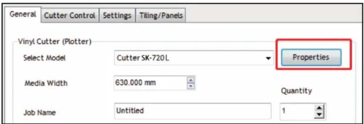
Click properties.
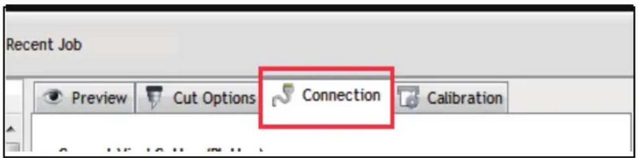
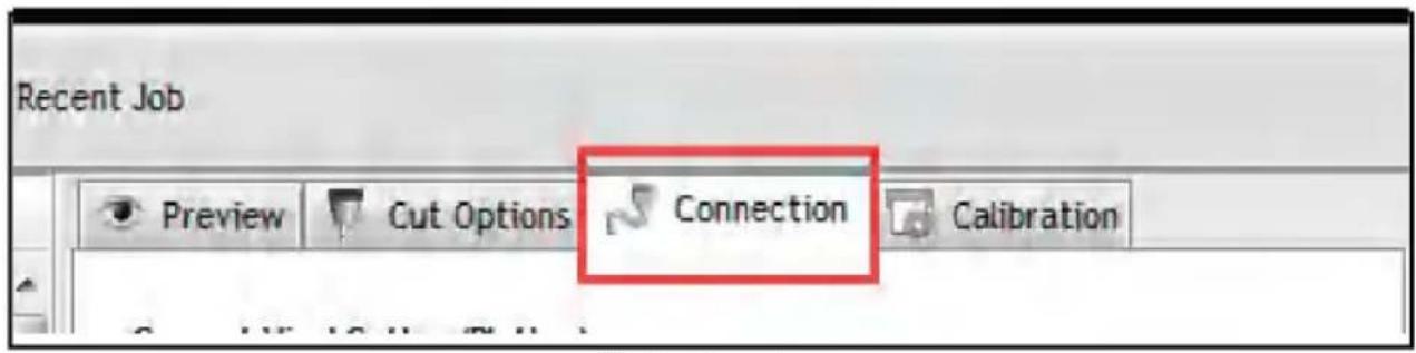
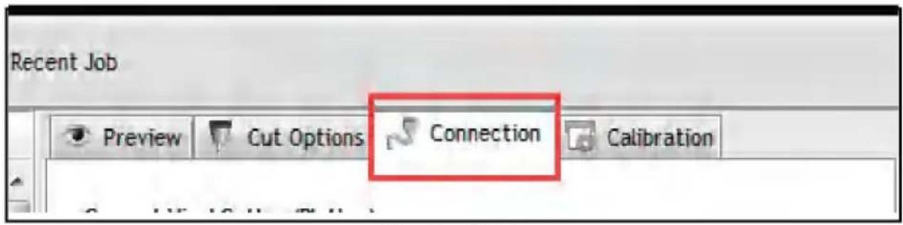
Click connection (pic 5-3).
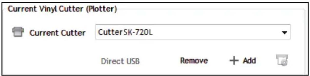
Select machine model (pic 5-4).
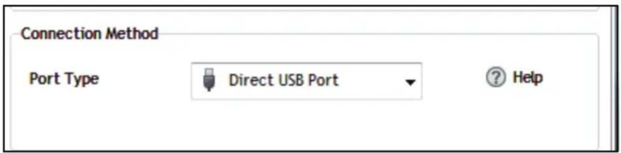
Select Direct USB Port (pic 5-5).
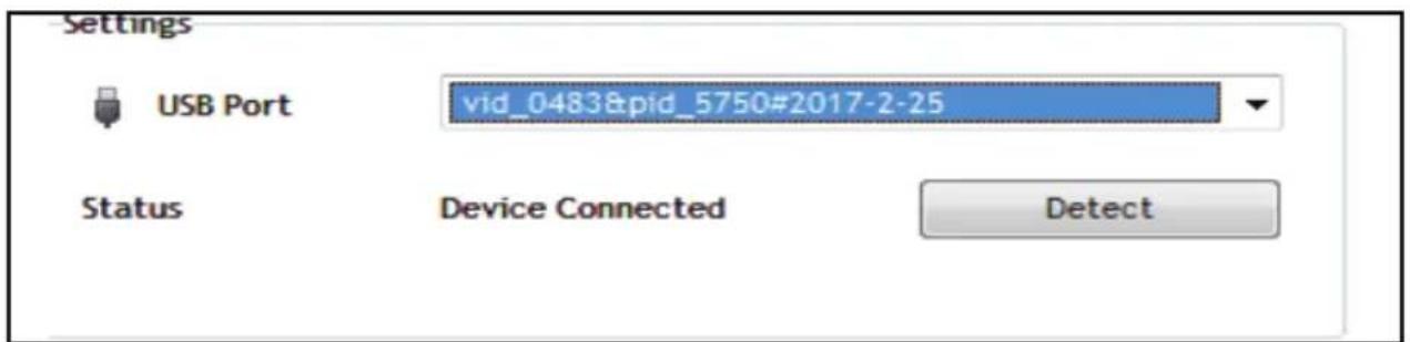
Drop-down select driver (pic 5-6).
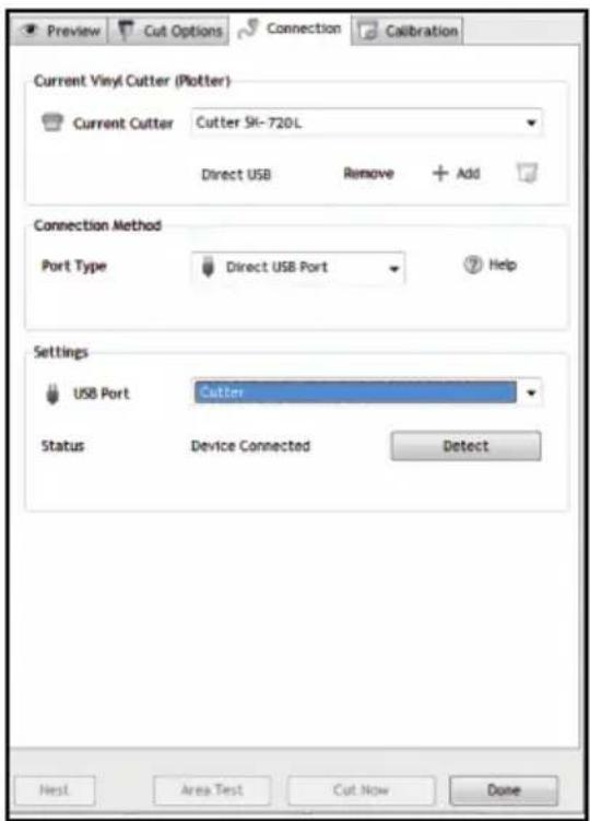
Click finish (pic 5-7).
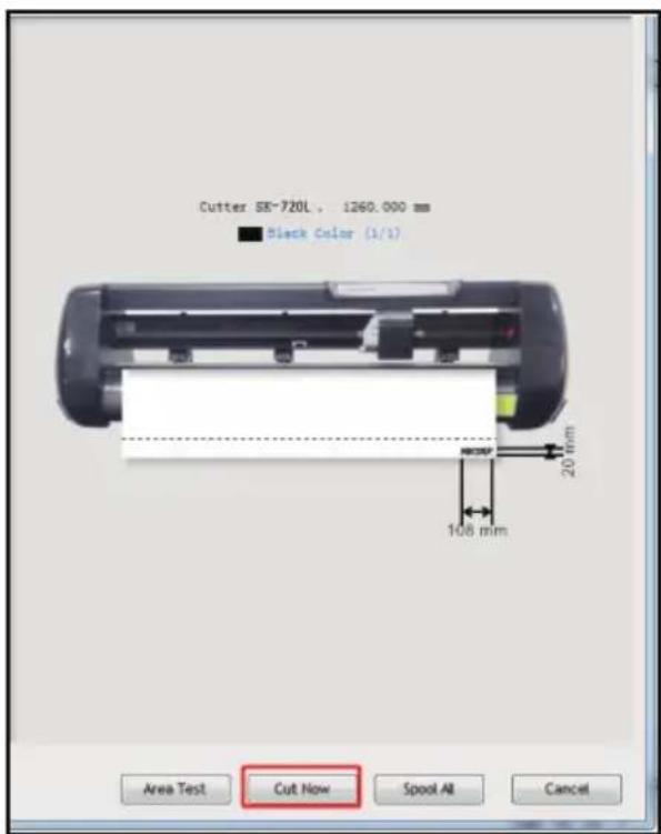
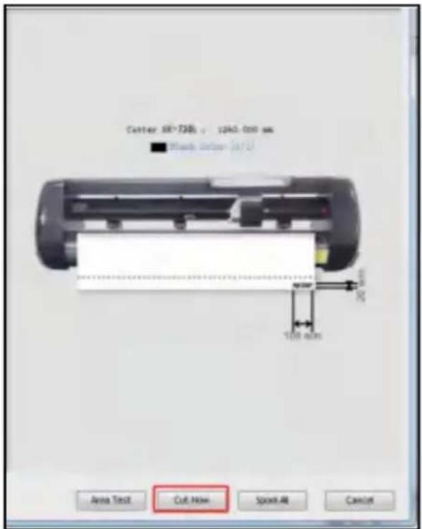
Click cut now (pic 5-8).
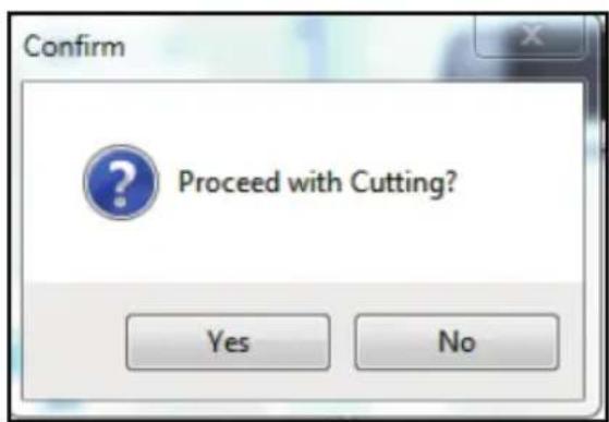
Click cut now (pic 5-9).
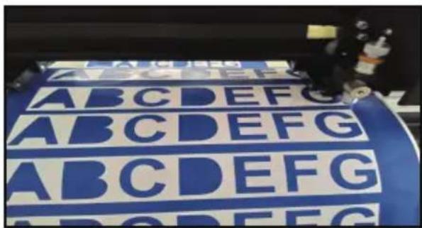
The output is completed, the cutting plotter is cutting (pic 5-10).
Note: Specific operation can refer to USB flash drive operation video, including as follows:
- Ordinary cutting video.
- Automatic deviation correction video.
- Automatic contour video.
- Software installation video.
APP OPERATION GUIDE
Note: This APP only supports Android system. There is no need to choose a language during installation; the software will install in the language of the phone's system.
- First, download the APP using any of the following methods.
a. Download link: http://apk.ahroto.com/CUT.apk b. You can also download the APP by scanning the following QR code with your browser.

2. Connection Operation Guide
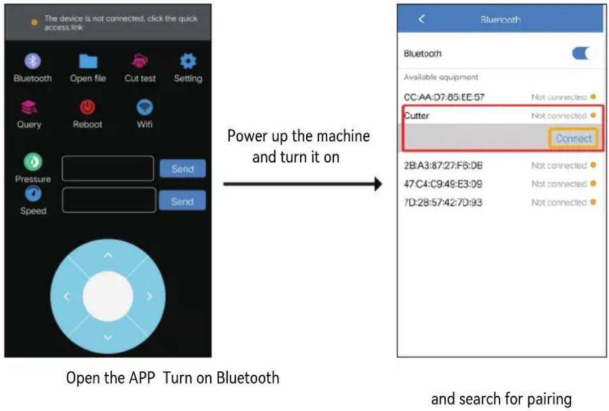
3. Function Introduction
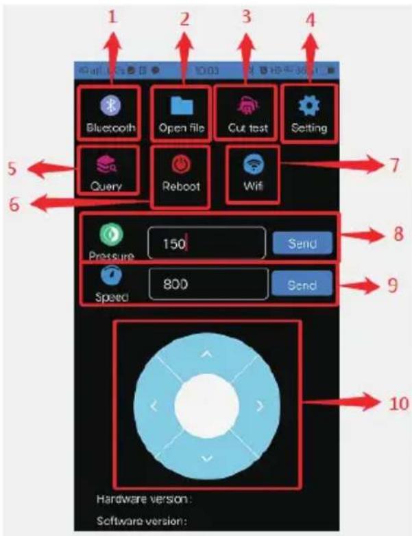
① Bluetooth management: Connect the plotter via Bluetooth. ② File management: Search for downloaded PLT files and send cutting files. ③ Cutting test: After loading materials, you can use the test cutting function to check if the knife pressure is appropriate. ④ Settings: You can change port mode, gear ratio, and machine language. Light settings and camera settings are not related to this machine; do not change these parameters. ⑤ Version query: Check the hardware and software versions. ⑥ Restart function: Press this button to restart the machine. ⑦ WiFi connection: This machine does not support WiFi; no need to set or connect this function.
⑧ Pressure display bar: This displays the current pressure value of the machine and allows you to change it.
⑨ Speed display bar: Here you can display current machine speed values and change speed values.
⑩ Sports carriage and material control area: After connecting the machine, you can control the carriage of the machine and move the material to determine the cutting position.
- Send Cutting file
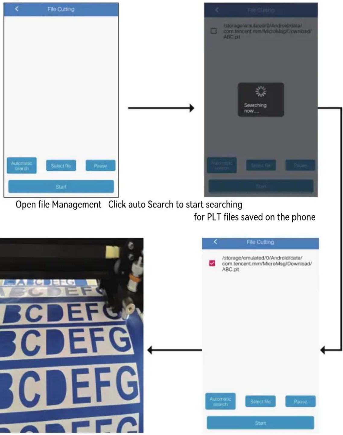
Effect of cutting Select the file and click cut
TROUBLESHOOTING
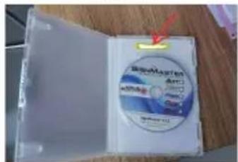
- PSN code is required during software installation. Where is this code?
Solution: The software code is in the CD box, you can see it when you open it, as shown below:
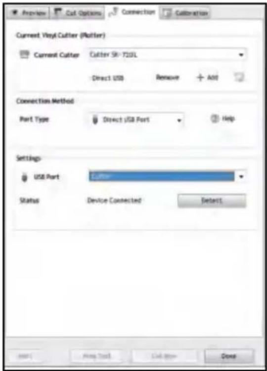
- Computer software can't connect to the plotter?
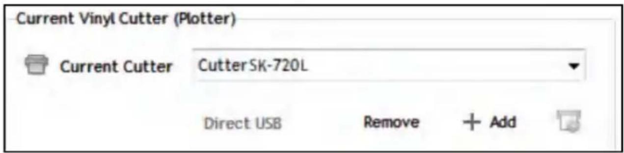
Solution: The software is not set properly. Open the software cutting background and select USB as the port type, as shown below:
![graph TD A["Settings"] --> B["Device Not Connected"] B --> C["Detect"] D["Preview"] --> E["Cut Options"] E --> F["Connection"] F --> G["Calibration"] H["Vinyl Spooler"] --> I["Submit Feedback..."] I --> J["Gateway..."] J --> K["Settings/Preferences..."] L["Current Vinyl Cutter (Plotter)"] --> M["Cut…](/content/2026/04/736595/images/7e14207a0a1ac8a6ce4d4bd5632aadff642bd73bad06539faca0035724e5baea.jpg)
- What should I do if MY mobile APP cannot connect to the cutting plotter?
Solution: Restart the plotter because the Bluetooth port is occupied.
- What should I do if the display blinks or blue screen when I start it?
Solution: In this case, the control card is damaged, and you need to contact the after-sales service to replace the accessories.
DISPOSAL
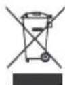
This product is subject to the provisions of European Directive 2012/19/EC.
Products marked with the logo on the right require separate waste collection in the EU.
This rule applies to all products and accessories bearing this mark.
Products containing the label on the right must not be discarded with general household waste and must be sent to a collection point for recycling of electrical and electronic equipment.
ATTENTION
Attention: This device complies with Part 15 of the FCC Rules. Operation is subject to the following two conditions:
- This device may not cause harmful interference,
- this device must accept any interference received, including interference that may cause undesired operation.
Manufacturer: Shanghaimuxinmuyeyouxiangongsi
Address: Shuangchenglu 803nong11hao1602A-1609shi, baoshanqu, shanghai 200000 CN.
EC REP: E-CrossStu GmbH. Mainzer Landstr.69, 60329 Frankfurt am Main.
UK REP: YH CONSULTING LIMITED. C/O YH Consulting Limited Office 147, Centurion House, London
Road, Staines-upon-Thames, Surrey, TW18 4AX
Imported to AUS: SIHAO PTY LTD. 1 ROKEVA STREETEASTWOOD NSW 2122 Australia
Imported to USA: Sanven Technology Ltd. Suite 250, 9166 Anaheim Place, Rancho Cucamonga, CA
91730
VEVOR®
Technical Support and E-Warranty Certificate
www.vevor.com/support
VEVOR®
INTRODUCTION TO MAIN PARTS
SK Models
Left side
Right side
- Rail cover
Set
DESCRIPTION OF CONTROL BUTTONS AND OPERATING INSTRUCTIONS
Exploded view
Correct
Tips:
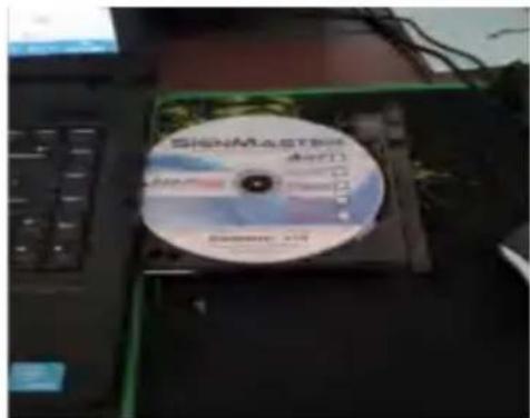
photo 2 photo 1
photo 3
SOFTWARE AND MACHINE CONNECTION
Click properties
House, London Road, Staines-upon-Thames, Surrey, TW18 4AX
Imported to AUS: SIHAO PTY LTD. 1 ROKEVA STREETEASTWOOD NSW 2122 Australia
Imported to USA: Sanven Technology Ltd. Suite 250, 9166 Anaheim Place, Rancho Cucamonga, CA 91730
VEVOR®
Correct
Staggerment:
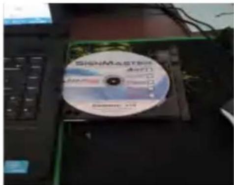
photo 2photo 1
photo 3
Select
the unit pic 4-6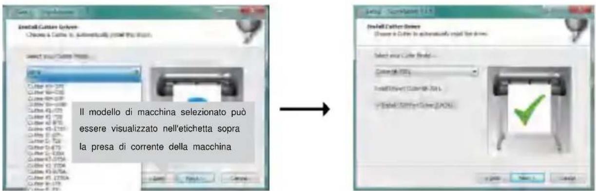
Next photo 4-9
SOFTWARE AND MACHINE CONNECTION
Click on End photo 5-7
London Road, Staines-upon-Thames, Surrey, TW18 4AX
Imported into AUS: SIHAO PTY LTD. 1 ROKEVA STREETEASTWOOD NSW 2122 Australia
Imported into the USA: Sanven Technology Ltd. Suite 250, 9166 Anaheim Place, Rancho Cucamonga, CA 91730
VEVOR®
Cutting plotter machine
USER MANUAL
VEVOR®
Cutting plotter machine
Correct
Tips:
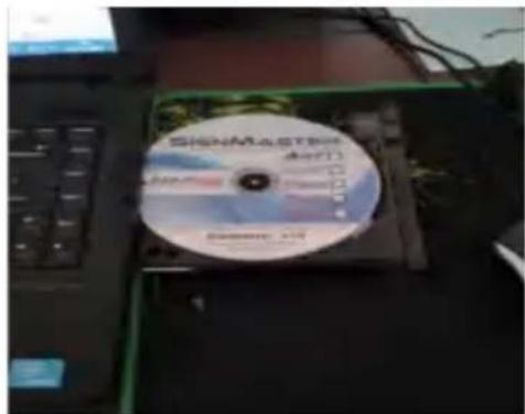
photo 2Photo 1
photo 3
NEED HELP? CONTACT US
CONTROL BUTTONS DESCRIPTION AND USER INSTRUCTIONS
![graph TD A["Välkomna"] --> B["Hastighet 800mm\s Kraft 105g"] B --> C["Ställa in språk kinesiska"] C --> D["X skala 10000\nY skala 10000"] D --> E["Virtuell COM N\nSkrivare\nY"] F["Offline"] --> B G["Ställa in språk engelska"] --> C H["eller"] --> C I["X= 0\nY= 0"] --> B J["V+"] --> C K["V-"] --> C L…](/content/2026/04/736595/images/3372b3ea98e3125fd7e62687ecb0bd207efd9f62b5be51ee2e8e2c7fc0f7ccf6.jpg)
PRODUCT ASSEMBLY STEPS
Exploded view
Correct
Tips:
- Place the blade carriage in the carriage arm.
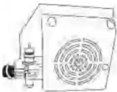
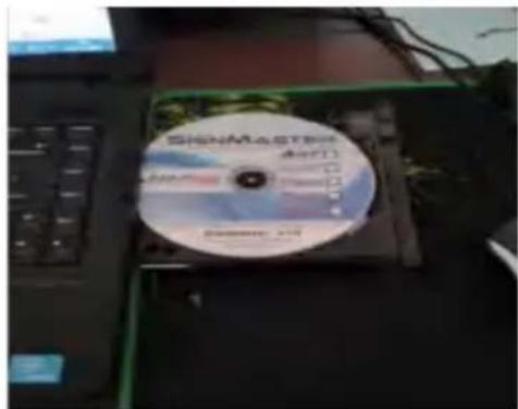
image 2image 1
image 3
CONNECTING PROGRAM AND MACHINE
Select driver in the dropdown menu image 5-6
UK REP: YH CONSULTING LIMITED. C/O YH Consulting Limited Office 147, Centurion House, London
Road, Staines-upon-Thames, Surrey, TW18 4AX
Imported to AUS: SIHAO PTY LTD. 1 ROKEVA STREETEASTWOOD NSW 2122 Australia
Imported to USA: Sanven Technology Ltd. Suite 250, 9166 Anaheim Place, Rancho Cucamonga, CA 91730
VEVOR®
Cutter plotter machine
USER MANUAL
VEVOR®
Cutting Plotter Machine
User Manual
Exploded view
Correct
Tips:
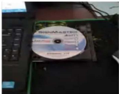
photo 2 photo 1
photo 3
Installation is complete, photos 4-10
Next photos 4-9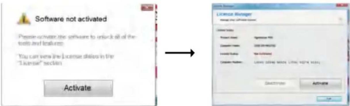
CONNECTING SOFTWARE AND MACHINE
Click connection photo 5-3
Select machine model photo 5-4
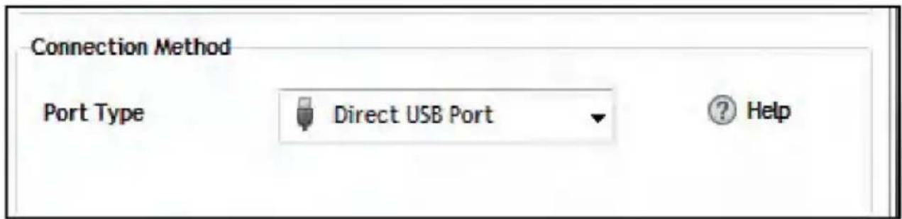
Select Direct USB port pic 5-5
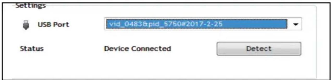
Driver selection menu pic 5-6

VK REP: YH CONSULTING LIMITED. C/O YH Consulting Limited Office 147, Centurion House, London Road, Staines-upon-Thames, Surrey, TW18 4AX
SYMBOL INDICATION
DESCRIPTION OF CONTROL BUTTONS AND OPERATING INSTRUCTIONS
![graph TD A["Accueillir"] --> B["Vitesse 800mm\s Force 105g"] B --> C["Réglage de la langue Chinois"] C --> D["Échelle X 10000 Échelle Y 10000"] D --> E["COM N virtuel Imprimante Y"] F["X= 0\nY = 0"] --> G["Hors ligne"] H["Réglage de la langue Anglais"] --> I["OU"] I --> J["V+"] I --> K["V-"] L["INST…](/content/2026/04/736595/images/bb9ac72ac088a92bd8128dd5dc652379dc727392c61d7bdfd38ec21220d68c0a.jpg)
PRODUCT ASSEMBLY STEPS
Exploded view
Correct
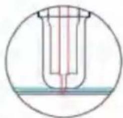
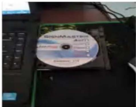
photo 2photo 1
CONNECTING THE SOFTWARE AND THE MACHINE
London Road, Staines-upon-Thames, Surrey, TW18 4AX
Imported into Australia: SIHAO PTY LTD. 1 ROKEVA STREETEASTWOOD NSW 2122 Australia
Exploded view
Correct
Tips:
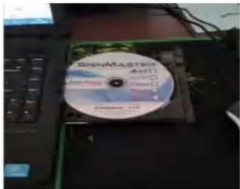
Image 2Image 1
Click on
UK REPRESENTATIVE: YH CONSULTING LIMITED. C/O YH Consulting Limited Office 147, Centurion House,
London Road, Staines-upon-Thames, Surrey, TW18 4AX
Imported into AUS: SIHAO PTY LTD. 1 ROKEVA STREETEASTWOOD NSW 2122 Australia
Imported into the USA: Sanven Technology Ltd. Suite 250, 9166 Anaheim Place, Rancho Cucamonga, CA 91730