
SP-HL-S252810-15A - Electrical enclosure Vevor - Free user manual and instructions
Find the device manual for free SP-HL-S252810-15A Vevor in PDF.
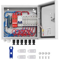


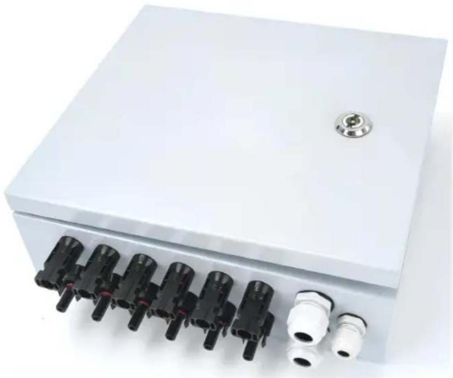
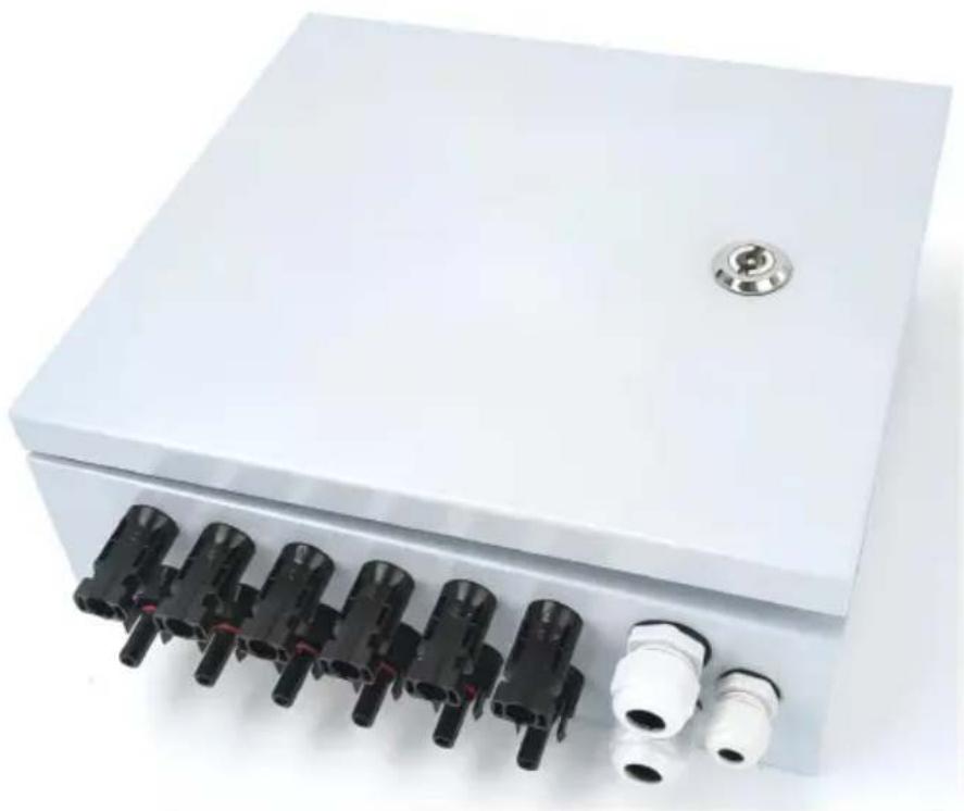
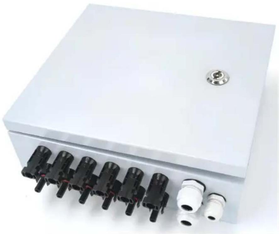
| Product Type | Photovoltaic Combiner Box |
| Brand | Vevor |
| Model | SP-HL-S252810-15A |
| Number of PV Inputs | 6 |
| Maximum Current per Input | 15 A |
| Fuse per Input | 15 A |
| Number of Outputs | 1 |
| Maximum Output Current | 90 A |
| Maximum Output Voltage | 500 VDC |
| Output Circuit Breaker | Yes (63A/125A 2P DC500V) |
| Surge Protection (SPD) | Yes (SU6-40KA 2P DC500V) |
| Protection Rating | IP66 |
| Operating Temperature Range | -30 °C to +60 °C |
| Cooling Mode | Natural Cooling |
| Input Wire Cross-Section | 2.5 mm² |
| Output Wire Cross-Section | 16 mm² |
| Housing Material | Sealed Metal |
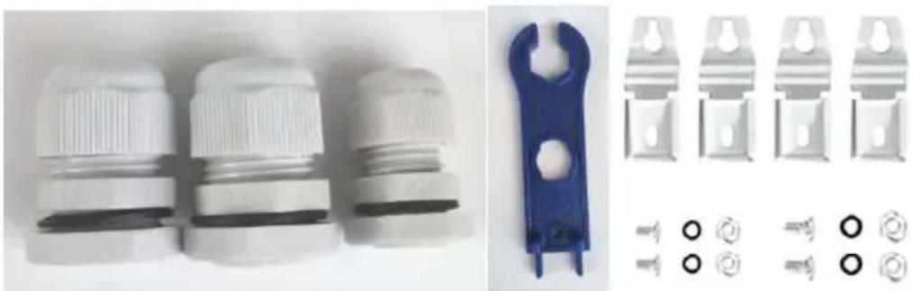
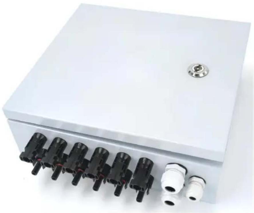
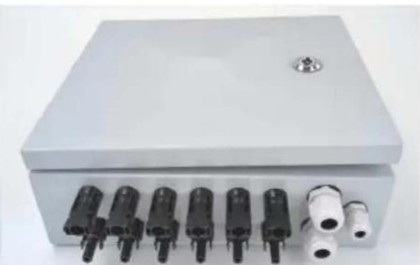
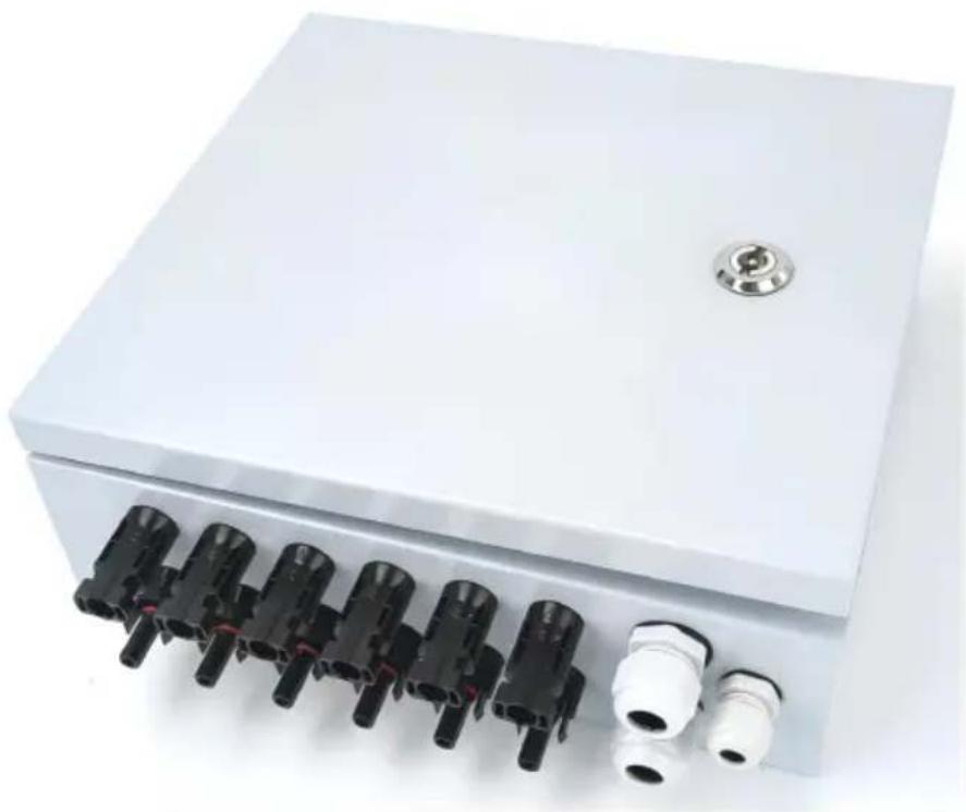
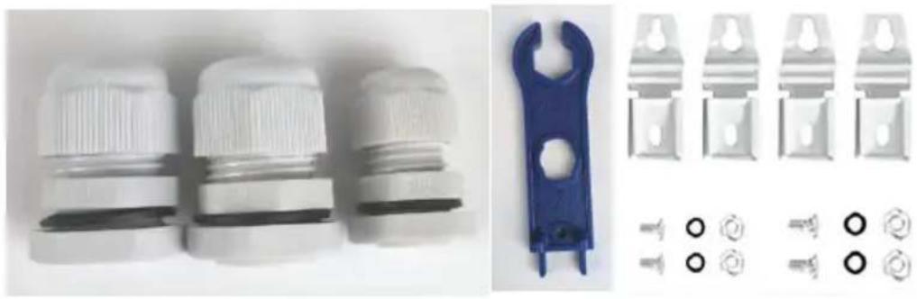
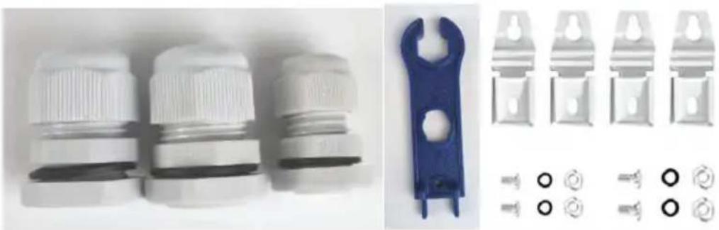
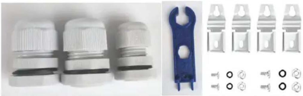
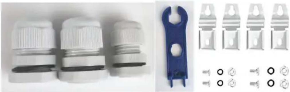
| Included Accessories | MC4 connectors (male and female), PG13.5 and PG9 cable glands, MC4 tool, wall mounting brackets |
| Warranty | 1 year |
Frequently Asked Questions - SP-HL-S252810-15A Vevor
User questions about SP-HL-S252810-15A Vevor
0 question about this device. Answer the ones you know or ask your own.
Ask a new question about this device
Download the instructions for your Electrical enclosure in PDF format for free! Find your manual SP-HL-S252810-15A - Vevor and take your electronic device back in hand. On this page are published all the documents necessary for the use of your device. SP-HL-S252810-15A by Vevor.
USER MANUAL SP-HL-S252810-15A Vevor
PV COMBINER BOX
Model: SP-HL-S252310-15A
SP-HL-S252810-10A
SP-HL-S252810-15A
We continue to be committed to provide you with tools at competitive prices. "Save Half", "Half Price" or any other similar expressions used by us only represent an estimate of savings you might benefit from buying certain tools with us compared to top brands and does not necessarily mean to cover all categories of tools offered. We kindly remind you to verify carefully when placing an order with us that you are actually saving half in comparison with the top major brands.
Model: SP-HL-S252310-15A / SP-HL-S252810-10A / SP-HL-S252810-15A
NEED HELP? CONTACT US!
Have product questions? Need technical support? Please feel free to contact us:
This is the original instruction. Please read all manual instructions carefully before operating. VEVOR reserves a clear interpretation of the user manual. The appearance of the product shall be subject to the product you received. Please forgive us that we won't inform you if there are any technology or software updates on our product.
 | Warning-To reduce the risk of injury, user must read instructions manual carefully. |
 | This device complies with Part 15 of the FCC Rules. is subject to the following two conditions:(1)This device not cause harmful interference, and (2)this device must any interference received, including interference that may cause undesired operation. |
 | This product is subject to the provision of European D 2012/19/EC. The symbol showing a wheelie bin crossed through indicates that the product requires separate refu collection in the European Union. This applies to the p and all accessories marked with this symbol. Products as such may not be discarded with normal domestic w must be taken to a collection point for recycling electri electronic devices |
Identification and Description
In order to better use the product, please read the following instructions carefully.

WARNING!
This symbol identifies that informal operation may be dangerous to the safety of users or may cause significant hardware damage.
Installation: Please read this manual before use.

WARNING!
All operations and line connections must be performed by qualified personnel.
 | WARNING!Please pay attention to personal and equipment |
 | WARNING!Please note that photovoltaic array input of posit and negative polarity and the total output of the and negative polarity. |
 | WARNING!Installation or connection pv modules,please note modules high voltage,avoid produce shock hazard |
 | WARNING!Ensure that the connection of fastening,for the u use improper or cable wiring the loss caused by unstable, vevor company does not undertake any responsibility. |
Product Introduction
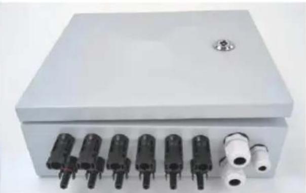
In photovoltaic power generation systems, to reduce the connecting cables between photovoltaic modules and inverters, facilitate maintenance, reduce losses, and improve product safety and reliability, a combiner device is generally required between the photovoltaic modules and the inverter.
In addition to the function of PV bus, the photovoltaic junction box should also have current counter-attack, over-current protection, over-voltage protection, lightning protection, and a set of comprehensive protection functions.
This company produces photovoltaic junction boxes that meet the above functional requirements, and they can be used with photovoltaic (PV) grid-tied inverters to form a complete photovoltaic power generation system solution.
When selecting a photovoltaic junction box, the user can, according to the inverter's input voltage range and output power, connect a certain number of same-specification PV modules in series and parallel to form a PV module array, which is then connected to the photovoltaic junction box (see Figure 1). After circuit breaker control and lightning protection device protection, the output is used for the inverter.
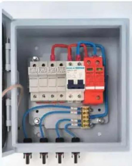
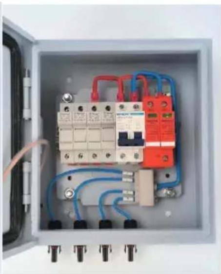
Figure 2 shows the related parts and their specifications.
![graph LR A["PV Combiner Box"] --> B["Solar Inverter"] B --> C["Power Grid"] D["Solar Panel"] --> A E["Power Load"] --> B](/content/2026/04/736461/images/08b5dcf5993cf05902ba8926347257cbde5102776464004eebbdc7d7660451ff.jpg)
Figure 1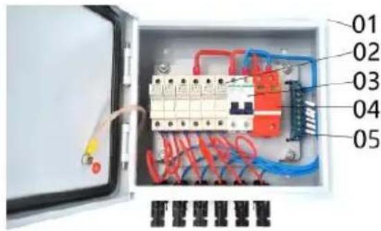
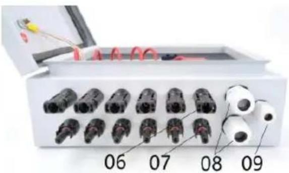
Figure 2
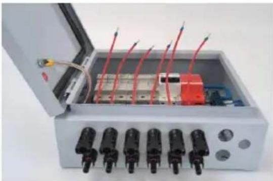
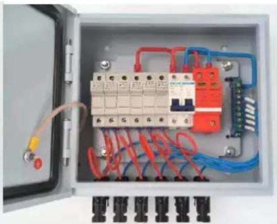
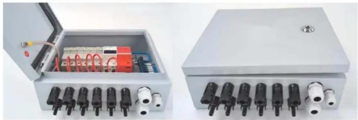
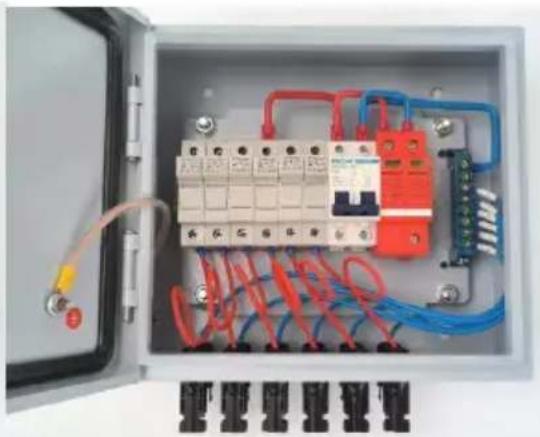
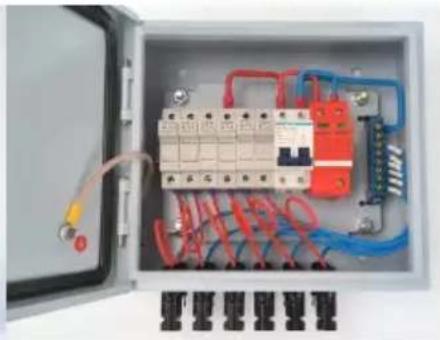
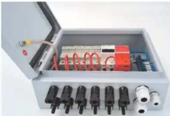
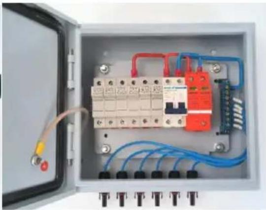
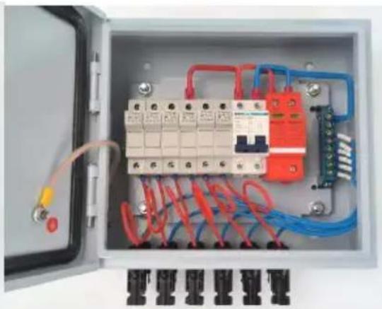
01---Waterproof Metal Box
02---4pcs/6pcs DC500V Fuse holder with 10/15A fuse
03---63A/125A 2P DC500V MCB
04---SU6-40KA 2P DC500V SPD
05---Neutral Bar
06---4pcs/6pcs Solar Female Connector
07---4pcs/6pcs Solar Male Connector
08---2pcs Output PG16 Cable Gland
09---Earthing PG9 Cable Gland
Production Specification
| Model | SP-HL-S252310-15A | SP-HL-S252810-10A | SP-HL-S252810-15A |
| PV array input numbers | 4 | 6 | 6 |
| Max single PV array curr | 15A | 10A | 15A |
| Single PV array fuse | 15A | 10A | 15A |
| Single PV array wire size | 2.5mm2 | ||
| Output numbers | 1 | ||
| Max output current | 60A | 60A | 90A |
| Output wire size | 10mm2 | 10mm2 | 16mm2 |
| Max output voltage | 500VDC | ||
| DC output circuit breaker | yes | ||
| Protection level | IP66 | ||
| Temperature range | -30°C ~ +60°C | ||
| Cooling way | Natural cooling | ||
| SPD protection | yes | ||
| Ground wire size | ≥ 2.5mm2 | ||
SP-HL-S252310-15A 4 input 1 output PV combiner box wiring diagram follows:
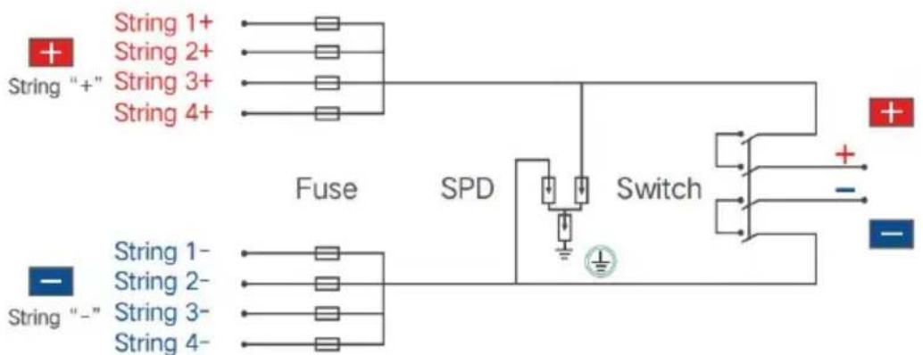
SP-HL-S252810-10A and SP-HL-S252810-15A 6 input 1 output PV combiner box wiring diagram as follows:
![graph TD A["String 1+"] --> B["Fuse"] C["String 2+"] --> B D["String 3+"] --> B E["String 4+"] --> B F["String 5+"] --> B G["String 6+"] --> B H["+"] --> I["Switch"] J["−"] --> I K["String 1-"] --> L["Fuse"] M["String 2-"] --> L N["String 3-"] --> L O["String 4-"] --> L P["String 5-"] --> L Q["Strin…](/content/2026/04/736461/images/5e411dc024f4668ea6fb441f87cb2bfd045f4f5c38a174fcb94713c4cdea2716.jpg)
PV Combiner Box Assembly Process
- Accessories list:
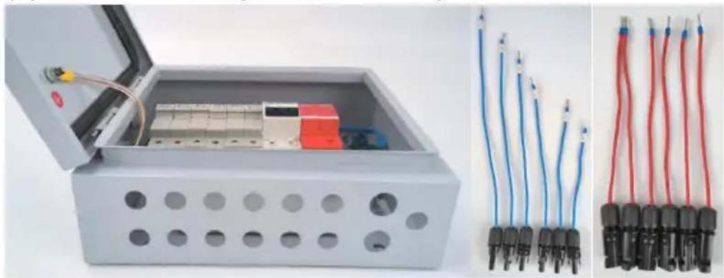
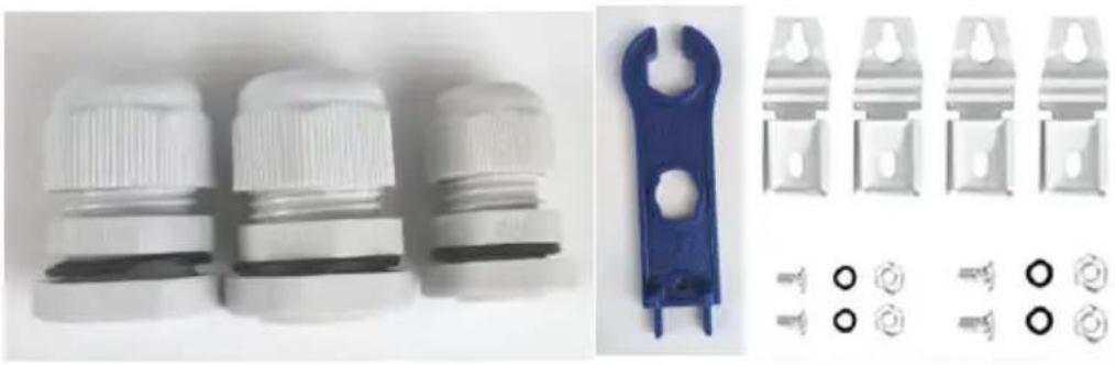
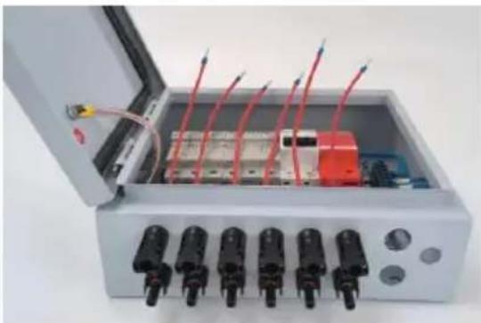
(1) half-finished PV combiner box---1pcs; (2) Input- MC4 male connector with cable----4pcs(for 4ways PV combir box)/6pcs(for 6ways PV combiner box);Tips:each cable is different length,there have number label on each cable,notice to distinguish. (3) Input+ MC4 female connector with cable----4pcs(for 4ways PV combiner box)/6pcs(for 6ways PV combiner box);Tips:each cable keep same length. (4) Output+ PG13.5 cable gland--1pcs; (5) Output- PG13.5 cable gland--1pcs; (6) Earthing PG9 cable gland--1pcs; (7) MC4 tool---1pcs; (8) Wall mounting brackets bag---1set;
2. Preparatory work
(1) Loose Input- MC4 female connector's mounting nut; (2) Loose Input+ MC4 female connector's mounting nut; (3) Loose 3pcs cable glands' mounting nut; (4) Loose terminal block's input terminals, make sure the following wirin process easy to fix; (5) Loose fuse holders' input fix screws, make sure the following wiring process easy to fix;
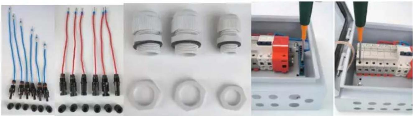
3. Wiring Input- MC4 male connector with cable
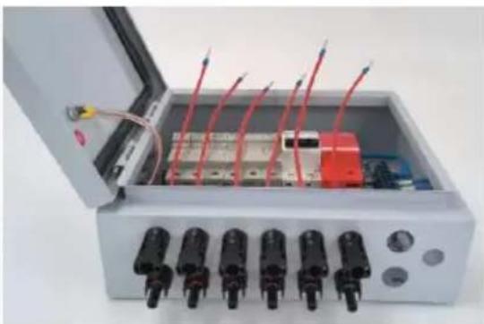
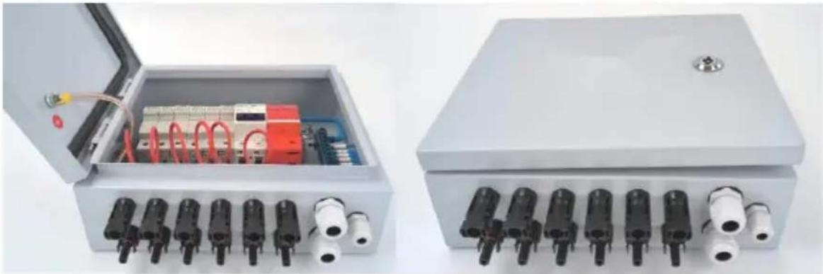
(1) Mounting No.1 cable on the picture 8 showed position, fix with nut (2) Mounting the rest of cables on the picture 9 showed position, fix a nut.the cable number from left to right shall is No.1-No.6;
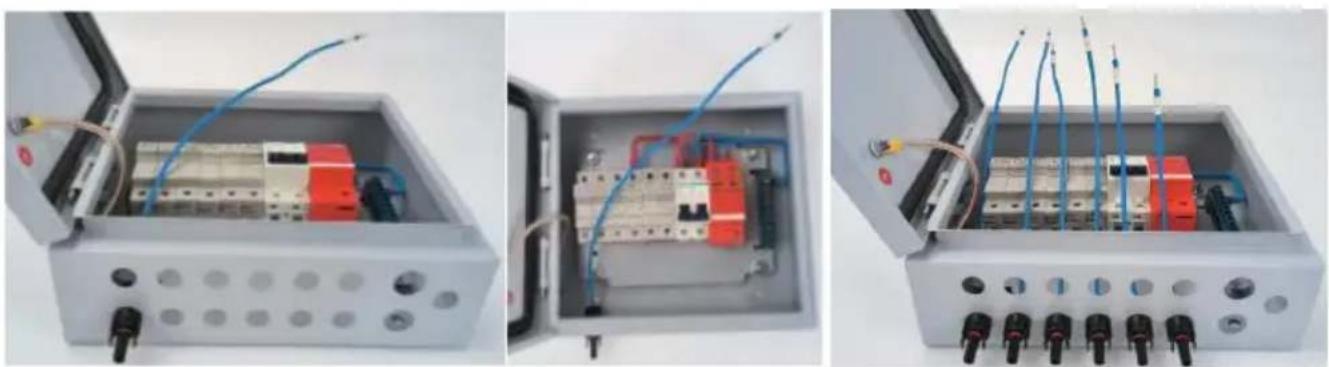
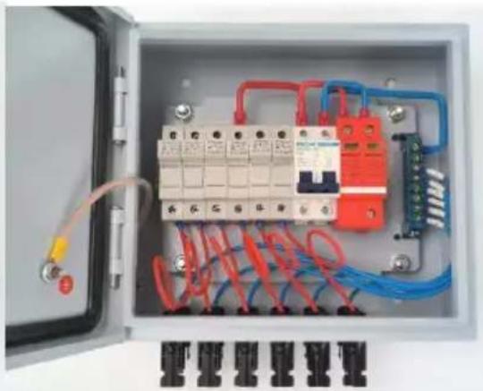
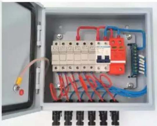
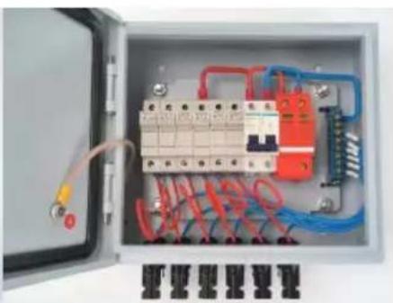
(3) Connect cable No. 6 to terminal block position No. 1; (4) Connect the remaining cables following the same process as step (3), step by step. The final state is as shown in the picture.
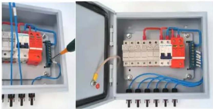
- Connect the Input+ MC4 female connector with the cable.
(1) Mount cable No. 1 in the position shown in picture 12, and secure it with the nut. (2) Mount the remaining cables in the positions shown in picture 13, and secure them with the nuts.
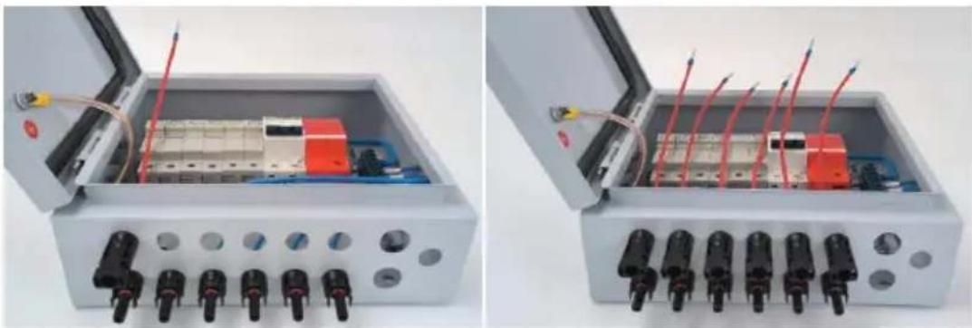
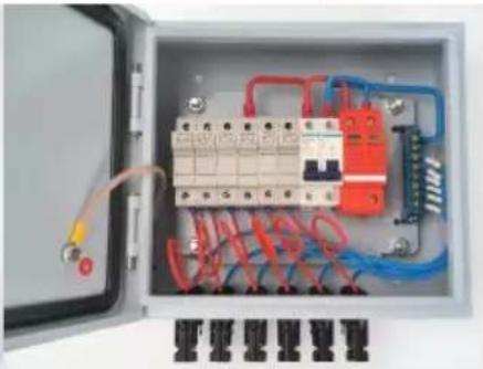
(3) Connect cable No. 1 to fuse holder No. 1, and tighten the fuse holder screw; (4) Connect the remaining cables following the same process as step (3), step by step. The final state is as shown in the picture.
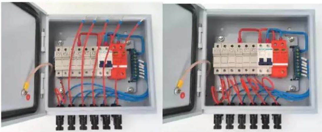
- Mount the output cable glands and the earthing cable gland.
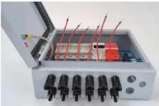
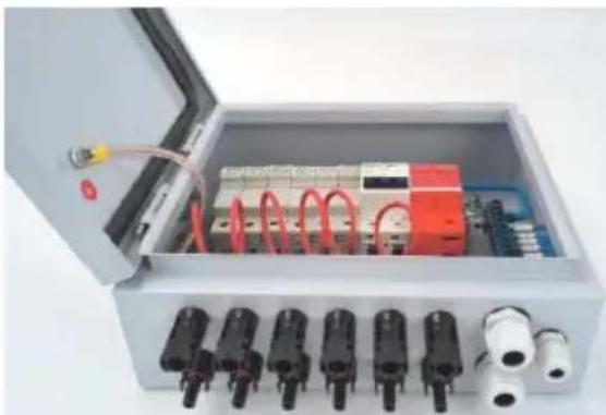
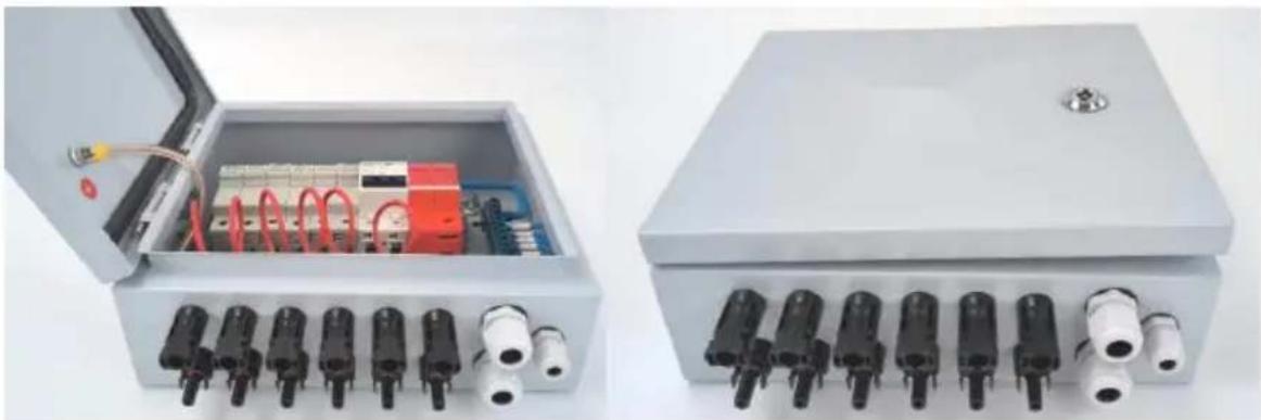
(1) Mount 2 pieces of PG13.5 cable glands in the 2 marked positions; (2) Mount 1 piece of PG9 cable gland in the marked position. The final state is as shown in the picture.
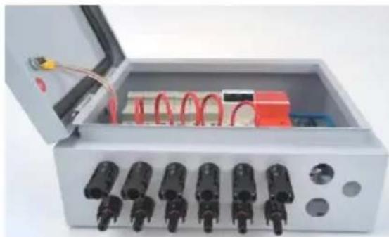
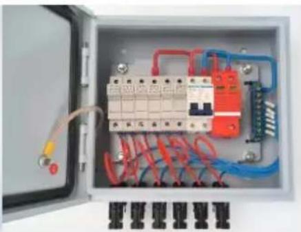
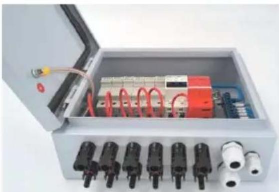
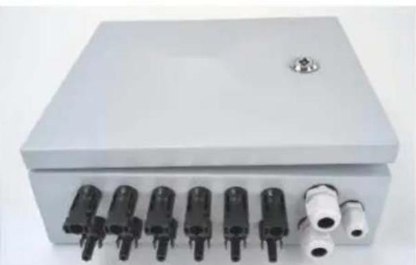
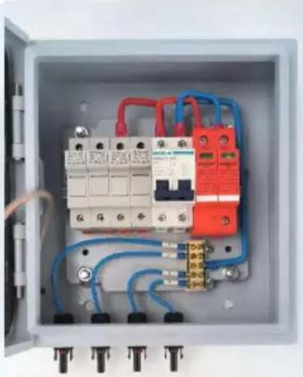
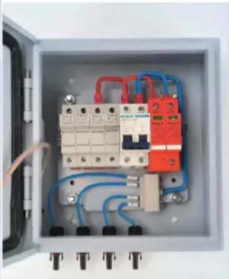
Tip: For the 4-way PV combiner box, there are some different steps when wiring the Input- MC4 male connector with cable compared to the 6-way PV combiner box. The rest of the process remains the same.
(1) Open the terminal block's cover as follows:
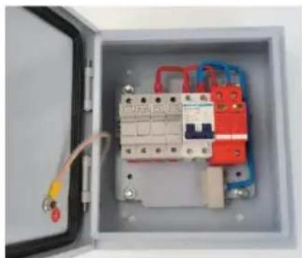
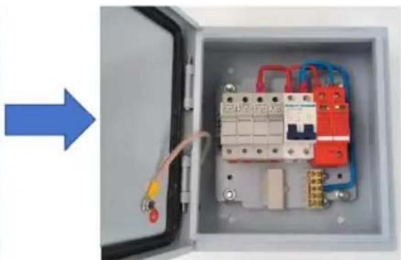
(2) Mount 4 pieces of Input- MC4 male connectors with cables and secure them using the same process as described above.
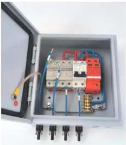
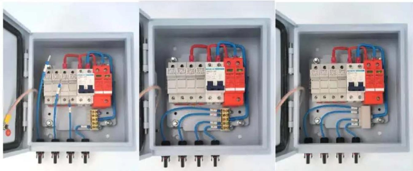
(3) Connect cable No. 4 to terminal block position No. 1; (4) Connect the remaining cables following the same process as step (3), step by step. Close the terminal block cover. The final state is as shown below.
Installation & Use
Installation: Use the matching screws to fix the 4 mounting buckles into the 4 holes on the side of the box. Users can select the appropriate position to mount the combiner box on the wall or panel.
Fast connection
(1) To improve the speed and convenience of connection, users can open the door of the combiner box and connect the photovoltaic array input wires to the corresponding terminals. Pay attention to the correct polarity (positive and negative) of the photovoltaic array input lines.
(2) The combiner box is designed as an independent set for photovoltaic array input/output. Through proper connection of the photovoltaic array inputs, the output power will be combined into one way, to match the one-way independent input controller used. (3) When users connect the system, please ensure that all line equipment is reliable.
Over-current protection
When the PV module input current is too large, the fuse will break to provide protection. In addition, the miniature circuit breaker can also prevent the system from having excessive current, thus providing over-current protection.

WARNING!
It is strictly prohibited to work on the fuse while it is live. Inspection or replacement must be performed only after the fuse and the DC circuit breaker are disconnected. The replacement fuse must be of the same model and rating as the original.
Over-voltage protection
When the PV module input voltage is high, the miniature circuit breaker will automatically disconnect, providing over-voltage protection.
Appendix
Quality assurance
This product has a quality assurance period of 1 year, unless otherwise stipulated in the contract, in which case the contract terms shall prevail.
Evidence
Products within the quality assurance period require customers to present the invoice and date of purchase. At the same time, the product's
trademark must be clearly visible; otherwise, the company reserves the right to refuse warranty service.
The following situations are not covered by the quality assurance:
- Man-made damage to the equipment
- Wrong installation and use
- When using the maximum limit parameters beyond equipment requirements;
- Abnormal natural environment damage caused;
- Operation in very bad environments beyond those described in this manual;
- Beyond the installation and use range specified in relevant international standards.
Address: Baoshanqu Shuangchenglu 803long 11hao 1602A-1609shi
Shanghai
Imported to AUS: SIHAO PTY LTD, 1 ROKEVA STREETEASTWOOD NSW 2122 Australia
Imported to USA: Sanven Technology Ltd., Suite 250, 9166 Anaheim Place, Rancho Cucamonga, CA 91730
| EC | REP |
SHUNSHUN GmbH
Römeräcker 9 Z2021, 76351
Unit 5 Albert Edward House, The
Pavilions Preston, United Kingdom
Made In China
VEVOR®
TOUGH TOOLS, HALF PRICE
Technical Support and E-Warranty Certificate www.vevor.com/support
VEVOR®
TOUGH TOOLS, HALF PRICE
We continue to be committed to provide you tools with competitive price. "Save Half", "Half Price" or any other similar expressions used by us only represent estimate of savings you might benefit from buying certain tools with us compared to top brands and does not necessarily mean to cover all categories of tools offered. We kindly remind you to verify carefully when you are placing an order with us to ensure you are actually saving half in comparison with the top major brands.
NEED HELP? CONTACT US!
Have product questions? Need technical support? Please feel free to contact us:
Technical Support and E-Warranty Certificate www.vevor.com/support
This is the original instruction. Please read all manual instructions carefully before operating. VEVOR reserves a clear interpretation of the user manual. The appearance of the product shall be subject to the product you received. Please forgive us that we won't inform you if there are any technology or software updates on our product.
Identification and Description
WARNING!
WARNING!
WARNING!
WARNING!
WARNING!
WARNING!
PV Combiner Box Assembly Process

WARNING!
Unit 5 Albert Edward House, The
Pavilions Preston, United Kingdom
Made in China
VEVOR®
TOUGH TOOLS, HALF PRICE
We continue to be committed to providing you with tools at competitive prices. "Save Half", "Half Price", or any other similar expressions used by us only represent the savings you might benefit from buying certain tools with us compared to top brands and do not necessarily mean to cover all categories of tools offered. We kindly remind you to verify carefully when placing an order with us to ensure you are actually saving half in comparison with the top major brands.
Model: SP-HL-S252310-15A / SP-HL-S252810-10A / SP-HL-S252810-15A
NEED HELP? CONTACT US!
Have product questions? Need technical support? Please feel free to contact us:
Technical Support and E-Warranty Certificate www.vevor.com/support
This is the original instruction. Please read all manual instructions carefully before operating. VEVOR reserves a clear interpretation of the user manual. The appearance of the product shall be subject to the product you received. Please forgive us that we won't inform you of any technology or software updates on our product.
Identification and Description
WARNING!
PV Combiner Box Assembly Process
11. Accessories list:
Installation & Use
WARNING!
Unit 5 Albert Edward House, The
Pavilions Preston, United Kingdom
We continue to be committed to provide you tools with competitive price. "Save Half", "Half Price" or any other similar expressions used by us only represent estimate of savings you might benefit from buying certain tools with us compared top brands and does not necessarily mean to cover all categories of tools offered are kindly reminded to verify carefully when you are placing an order with us actually saving half in comparison with the top major brands.
Model: SP-HL-S252310-15A / SP-HL-S252810-10A / SP-HL-S252810-15A
NEED HELP? CONTACT US!
Have product questions? Need technical support? Please feel free to contact us:
Technical Support and E-Warranty Certificate www.vevor.com/support
This is the original instruction, please read all manual instruction carefully before operating. VEVOR reserves a clear interpretation user manual. The appearance of the product shall be subject to product you received. Please forgive us that we won't inform you there are any technology or software updates on our product.
Identification and Description
WARNING!
WARNING!
WARNING!
WARNING!
WARNING!
WARNING!
PV Combiner Box Assembly Process
- Preparatory work
WARNING!
Imported into AUS: SIHAO PTY LTD, 1 ROKEVA STREETEASTWOOD NSW 2122 Australia
Imported into USA: Sanven Technology Ltd., Suite 250, 9166 Anah Place, Rancho Cucamonga, CA 91730
| EC | REP |
SHUNSHUN GmbH
Römeräcker 9 Z2021, 76351
Unit 5 Albert Edward House, The
Pavilions Preston, United Kingdom
Made in China
VEVOR®
TOUGH TOOLS, HALF PRICE
We continue to be committed to providing you tools with competitive prices. "Save Half", "Half Price" or any other similar expressions used by us only represent the savings you might benefit from buying certain tools with us compared to top brands, and do not necessarily mean that all categories of tools offered are covered. We kindly remind you to verify carefully when placing an order with us to ensure you are actually saving half in comparison with the top major brands.
Model: SP-HL-S252310-15A / SP-HL-S252810-10A / SP-HL-S252810-15A
NEED HELP? CONTACT US!
Have product questions? Need technical support? Please feel free to contact us:
Technical Support and E-Warranty Certificate www.vevor.com/support
This is the original instruction. Please read all manual instructions carefully before operating. VEVOR reserves the right to interpret the user manual. The appearance of the product shall be subject to the product you received. Please forgive us that we won't inform you of any technology or software updates on our product.
Identification and Description
WARNING!
PV Combiner Box Assembly Process
Installation & Use
WARNING!
Imported to AUS: SIHAO PTY LTD, 1 ROKEVA STREET, EASTWOOD NSW 2122 Australia
Imported to USA: Sanven Technology Ltd., Suite 250, 9166 Anal Place, Rancho Cucamonga, CA 91730
| EC | REP |
SHUNSHUN GmbH
Römeräcker 9 Z2021, 76351
Unit 5 Albert Edward House, The
Pavilions Preston, United Kingdom
Made in China
VEVOR®
TOUGH TOOLS, HALF PRICE
We continue to be committed to provide you tools with competitive price. "Save Half", "Half Price" or any other similar expressions used by us only represent estimate of savings you might benefit from buying certain tools with us compared to top brands and does not necessarily mean to cover all categories of tools offered. We kindly remind you to verify carefully when you are placing an order with us that you are actually saving half in comparison with the top major brands.
Model : SP-HL-S252310-15A / SP - HL-S252810-10A / SP-HL-S252810-15A
NEED HELP? CONTACT US!
Have product questions? Need technical support? Please feel free to contact us:
Technical Support and E-Warranty Certificate www.vevor.com/support
This is the original instruction. Please read all manual instructions carefully before operating. VEVOR reserves a clear interpretation of the user manual. The appearance of the product shall be subject to the product you received. Please forgive us that we won't inform you if there are any technology or software updates on our product.
Identification and Description
PV Combiner Box Assembly Process
Installation & Use
STREET EASTWOOD NSW 2122 Australia
Imported to USA: Sanven Technology Ltd., Suite 250, 9166 Anal Place, Rancho Cucamonga, CA 91730
| EC | REP |
SHUNSHUN GmbH
Römeräcker 9 Z2021, 76351
Unit 5 Albert Edward House, The
Pavilions Preston, United Kingdom
We continue to be committed to provide you tools with competitive price. "Save Half", "Half Price" or any other similar expressions used by us only represent estimate of savings you might benefit from buying certain tools with us compared to top brands and does not necessarily mean to cover all categories of tools offered. We kindly remind you to verify carefully when you are placing an order with us to ensure you are actually saving half in comparison with the top major brands.
Model: SP-HL-S252310-15A / SP-HL-S252810-10A / SP-HL-S252810-15A
NEED HELP? CONTACT US!
Have product questions? Need technical support? Please feel free to contact us:
Technical Support and E-Warranty Certificate www.vevor.com/support
This is the original instruction. Please read all manual instructions carefully before operating. VEVOR reserves a clear interpretation of the user manual. The appearance of the product shall be subject to the product you received. Please forgive us that we won't inform you if there are any technology or software updates on our product.
Identification and Description
WARNING!




WARNING!
PV Combiner Box Assembly Process
- Installation of output cable glands and grounding cable gland.
Installation & Use
WARNING!
Unit 5 Albert Edward House, The
Pavilions Preston, United Kingdom
Made in China
VEVOR®
TOUGH TOOLS, HALF PRICE
Technical Support and E-warranty Certificate www.vevor.com/support
VEVOR®
TOUGH TOOLS, HALF PRICE
We continue to be committed to provide you tools with competitive price. "Save Half", "Half Price" or any other similar expressions used by us only represent the estimate of savings you might benefit from buying certain tools with us compared to top brands and does not necessarily mean to cover all categories of tools offered. We kindly remind you to verify carefully when you are placing an order with us whether you are actually saving half in comparison with the top major brands.
Model: SP-HL-S252310-15A / SP-HL-S252810-10A / SP-HL-S252810-15A

NEED HELP? CONTACT US!
Have product questions? Need technical support? Please feel free to contact us:
Technical Support and E-Warranty Certificate www.vevor.com/support
This is the original instruction. Please read all manual instructions carefully before operating. VEVOR reserves the right to interpret the user manual. The appearance of the product shall be subject to the product you received. Please forgive us that we won't inform you of any technology or software updates on our product.
Identification and Description
WARNING!
Figure 2
01---Waterproof metal box
PV Combiner Box Assembly Process
37. Preparation
39. Wiring Input+ MC4 female connector with cable
Installation & Use
WARNING!
Unit 5 Albert Edward House, The
Pavilions Preston, United Kingdom
Made in China
VEVOR®
TOUGH TOOLS, HALF PRICE
www.vevor.com/support
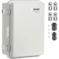
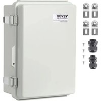

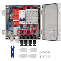
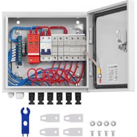
- PV COMBINER BOX
- NEED HELP? CONTACT US
- IDENTIFICATION AND DESCRIPTION
- WARNING
- PRODUCT INTRODUCTION
- PV COMBINER BOX ASSEMBLY PROCESS
- PREPARATORY WORK
- WIRING INPUT- MC4 MALE CONNECTOR WITH CABLE
- INSTALLATION & USE
- FAST CONNECTION
- OVER-CURRENT PROTECTION
- OVER-VOLTAGE PROTECTION
- APPENDIX
- QUALITY ASSURANCE
- EVIDENCE
- THE FOLLOWING SITUATIONS ARE NOT COVERED BY THE QUALITY ASSURANCE
- VEVOR®
- TOUGH TOOLS, HALF PRICE
Brand : Vevor
Model : SP-HL-S252810-15A
Category : Electrical enclosure