MMS4 - Slicer Vevor - Free user manual and instructions
Find the device manual for free MMS4 Vevor in PDF.

| Product Type | Manual Throatless Shear |
| Brand | Vevor |
| Model | MMS4 |
| Cutting Capacity (Mild Steel) | 14 Ga. (2.0 mm) |
| Cutting Capacity (Stainless Steel) | 18 Ga. (1.2 mm) |
| Cutting Width | 70 mm (2.76 in) |
| Blade Material | Hardened and Sharpened Steel |
| Drive Type | Gears |
| Weight (approx.) | Approx. 12 kg |
| Dimensions (L x W x H) (approx.) | 300 x 200 x 400 mm |
| Main Functions | Straight and curved cuts in soft metals |
| Maintenance | Regular lubrication of pivots and gears; cleaning of debris; replacement of blades if worn |
| Cleaning | Use mild solvents (mineral spirits) for blades, water and soap for painted parts |
| Safety | Wear ANSI Z87.1 safety glasses, thick gloves, non-slip shoes; keep hands away from blades; lock handle in down position after use |
| Main Spare Parts | Upper blade, lower blade, handle, fixing bolts (M5, M8, M12), adjustment screws |
| Repairability | Possible replacement of blades and adjustment of gap via screws |
| General Information | Manufacturer: Shanghai Muxinmuyeyouxiangongsi, Baoshan, Shanghai, CN. Imported into the US by Sanven, into Australia by SIHAO PTY LTD. CE Representative: 60329 Frankfurt am Main. |
Frequently Asked Questions - MMS4 Vevor
User questions about MMS4 Vevor
0 question about this device. Answer the ones you know or ask your own.
Ask a new question about this device
Download the instructions for your Slicer in PDF format for free! Find your manual MMS4 - Vevor and take your electronic device back in hand. On this page are published all the documents necessary for the use of your device. MMS4 by Vevor.
USER MANUAL MMS4 Vevor
Affordable. Reliable. Home Improvement.
Sheet Metal Plate Shear
MODEL:MMS4
VEVOR
Affordable. Reliable. Home Improvement.
Sheet Metal Plate Sheet
MODEL: MMS4
natural_image
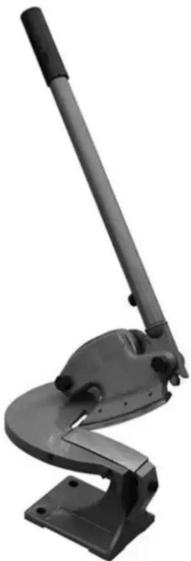
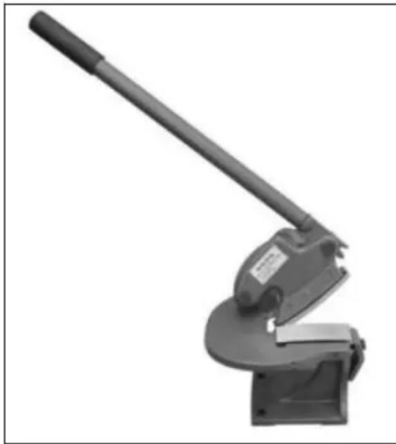
Black industrial machine tool with a curved base and lever mechanism (no visible text or symbols)This is the original instruction, please read all manual instructions carefully before operating. VEVOR reserves a clear interpretation of o user manual. The appearance of the product shall be subject to the product you received. Please forgive us that we won't inform you ag there are any technology or software updates on our product.

Warning-To reduce the risk of injury, user must read instructions manual carefully.
Unpacking
The 4" THROATLESS SHEAR is shipped from the manufacturer in a carefully packed Carton
box. Thoroughly inspect the product upon opening the package.
After unpacking the unit, carefully inspect for any damage that may have occurred during transit. Check for loose, missing, or damaged parts. Shipping damage claims must be filed with the carrier and are the responsibility of the user.
Specifications
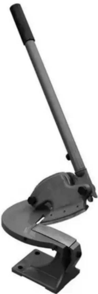
Your KAKA 4" THROATLESS SHEAR for metal cutting is precision designed manufactured to allow precise control when making straight or intricately curved cuts of any length, in any direction. Hardened, finely honed blades produce a burr-free cuts in aluminum, steel and other mild metals.
The gear-driven design delivers maximum shearing power with minimal handle force.
natural_image
Mechanical tool with lever mechanism (no visible text or symbols)Model.....MMS-4
Max. Capacity Mild Steel.....14 Ga. (2.0
Max. Capacity Staintess Steel.....18 Ga. (1.2 r
Width.....2.76" (70 mm)
Important
Blades are coated with a protectant. To ensure proper fit and operation, ren coating. Coating is easily removed with mild solvents, such as mineral spirits, a soft cloth. Avoid getting cleaning solution on paint or any of the rubber or parts. Solvents may deteriorate these finishes. Use soap and water on paint, plastic or rubber components. After cleaning, cover all exposed surfaces with light coating of oil.

WARNING : Never use highly volatile solvents. Non-flamm solvents are recommended to avoid possible fire hazards.
SAVE THESE INSTRUCTIONS
Thank you for purchasing our MMS-4 4" throatless shear machine. Before attempting to operate your new tool please read these instructions thoroughly. will need these instructions for the safety warnings, precautions, assembly, operation, maintenance procedures, parts list and diagrams. Keep your invoice number with these instructions. Write the invoice number on the inside of front cover. Keep the instructions and invoice in a safe, dry place for future reference
General Safety Information

CAUTION: Always follow proper operating procedures as in this manual even if you are familiar with use of this or s Remember that being careless for even a fraction of a secon result in severe personal injury.
SAFETY RULES
- Wear proper apparel. Do not wear loose clothing, gloves, neckties, rings, bracelets or other jewelry which may get caught in moving parts of machine.
- Wear protective hair covering to contain long hair.
- Wear safety shoes with non-slip soles.
-
Wear safety glasses complying with United States ANSI Z87.1. Everyday glasses have only impact resistant lenses. They are NOT safety glasses.
-
Be alert and think clearly. Never operate tools when tired, intoxicated or taking medications that cause drowsiness.
- Keep work area clean. Cluttered work areas invite accidents.
- Work area should be properly lit.
- Keep visitors at a safe distance from work area.
- Keep children out of workplace. Make workshop childproof. Use padlocks to prevent any unintentional use of tools.
- Assemble only according to these instructions. Improper assembly can create hazards.
- When tools are not in use, store them in a dry, secure place out of the children. Inspect the tools prior to storage and before reuse.
- Maintain product labels and nameplates. These carry important safety information.
KNOW HOW TO USE TOOL
- Use right tool for job. Do not force tool or attachment to do a job for wr not designed.
- Keep hands out of path of shear blades.
- The Max. shearing thickness of this machine is 14 Ga. (2.0mm) Mild Steel. Exceeding capacity may be dangerous to operator and damage may occur to machine.
- Bolt machine to floor or sturdy stand that is bolted to floor to prevent slidi tipping of machine.
- Strenuous physical force may need to be applied to the Throatless Shear cause. Failure to ensure proper footing can quickly result in a fall which could be serious personal injury or property damage. Always work in a clean, uncluttered environment.
- Be sure there is sufficient working room around the tool to allow for safe of various sizes of metal.
- The KAKA Throatless Shear was specifically designed to be operated by or person only. Never have one person operate the Handle while another handle workpiece or serious injury could occur.
- Frequently inspect Blades. If cracks or chips develop, discontinue tool use immediately and replace damaged Blades.

WARNING
The warnings, cautions, and instructions discussed in this instruction manual cannot cover all possible conditions or situations that occur. It must be understood by the operator that common secaution are factors that cannot be built into this product, but used by the operator.

WARNING
- This tool has EXTREMELY SHARP cutting blades with ampli leverage on the upper blade which can quickly cause severe or loss of fingers! Keep fingers and hands away from moving when operating.
- Always place the handle in the DOWN position with the Loop inserted through both the Upper Blade Housing and the Body CLOSED position (Figure 1) when not in use. The weight of left in the up position, can cause the upper blade to sudden unexpectedly drop with great force resulting in severe injury or fingers.
- Handling sharp metal can cause serious cuts. Wear thick, w work gloves to prevent cuts from handling sharp metal.
- Metal particles can be ejected from the material when cutting metal edges and corners are sharp and can injure eyes. Alwa ANSI approved eye protection when operating this tool.
Assembly
- The KAKA Throatless Shear must be securely mounted on a heavy, solid workbench, stand, floor etc., capable of holding the static weight of the unit the stresses from operation.
- Place the Throatless Shear over the chosen location then mark mounting hot locations by tracing holes in the base.
Assembly
-
The KAKA Throatless Shear must be securely mounted on a heavy, solid workbench, stand, floor etc., capable of holding the static weight of the unit the stresses from operation.
-
Place the Throatless Shear over the chosen location then mark mounting hot locations by tracing holes in the base.

CAUTION
Check for the presence of electrical, air or other utility lines u mounting surface before drilling mounting holes.
- The use of 1/2" through bolts & nuts or longer lag screws with substantial wa and attachment to a structural member is absolutely necessary.

CAUTION
Always keep the handle in the down position and the Body i CLOSED position (Figure 1) when not cutting. The weight of handle can cause the upper blade to suddenly and unexpected
natural_image
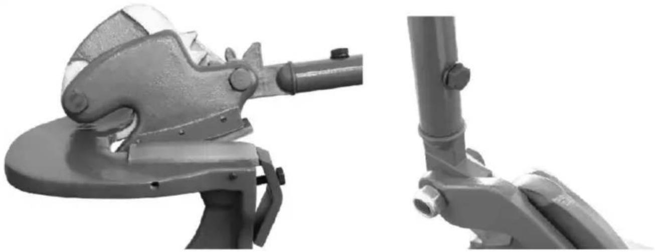
Close-up of two industrial tools: a saw cutting machine and a mechanical bracket (no text or symbols visible)Figure 1 Figure 2
- Remove the supplied bolt #3 from the Handle Stub #5, carefully align the mounting hole of the Handle #2 over the threaded hole in the Stub, thread through hole in Handle and into the Stub then tighten using a 13mm wrench included) (Figure 2).
Operation
- For Maximum Control and Cutting Force, begin all cuts by raising the head #2 fully and placing the edge of the metal at the point at which the blades meet.
- For Straight Cuts; keep the metal stationary and flat against shear deck a draw the handle #2 downward. As the 1st cut has been done and the upper #12 has reached the low point, raise the handle then move the material for placing the uncut area once again at the blade intersection point.
- For Curved Cuts; turn the material left or right to make curved cuts as n (NOTE: Do not move material forward as you cut). As the upper blade #12 reaches the low point, raise the handle then move the material forward placir uncut area once again at the blade intersection point. Resume left or right n movement.

WARNING
The weight of the handle can cause the upper blade to sud unexpectedly drop. When cuts are done, always place the hand the DOWN position.
BLADE ADJUSTMENT
NOTES
- The upper blade is fixed in place while the lower blade is adjustable.
- The ideal blade gap is equal to 1/4 of the subject material thickness.
For example: 14-gauge steel will work best with a blade gap of 0.019" [0.48 while 20 gauge should be 0.0094" [0.23mm].
- An alternative method is to gradually decrease blade gap while cutting paper. The paper should cut cleanly without pulls, tearing or folding.

CAUTION
Do not allow blades to come into full contact with each other permanent blade damage can occur.
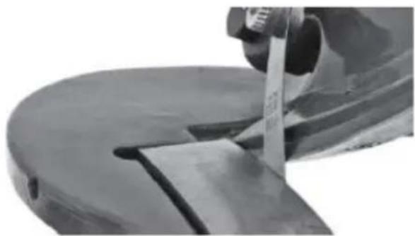
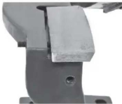
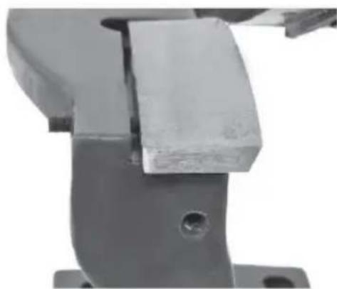
To measure: use a good quality feeler gauge and measure at the blade intersection point with the handle at the halfway down position (Figure 3).
natural_image
Close-up of a mechanical component with a tool inserted, showing a curved surface and a rectangular cutout (no visible text or symbols)Figure 3
TO ADJUST
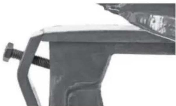
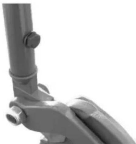
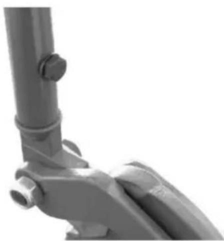
- Loosen the bolt #10 securing the Lower Blade Clamp at the left front of the (Figure 4).
natural_image
Close-up of a metal bracket with a bolt and clamped spring (no text or symbols visible)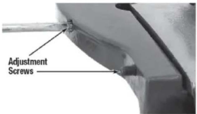
Figure 4 Figure 5
- Using a small, straight bladed screwdriver, Turn the two set screws #15 & (Figure 5) inward (clockwise) to decrease blade gap, turn outward (counter-clockwise) while applying a slight outward pressure to increase blade gap.
NOTE: Turn screws an equal amount and no more than 1/4 turn at a time making adjustments.
- Re-tighten blade clamp bolt #10.
BLADE REPLACEMENT

WARNING
The blades are extremely sharp! Use extreme care when hand avoid severe cuts or loss of fingers!
UPPER BLADE
Removal
-
Raise Drive Gear Stub/Handle into the up position.
-
Remove Handle.

WARNING :Handle MUST be removed prior to blade rece the chance of blade accidentally falling.
- Loosen and remove 3 Phillips blade retaining screws #13 form the unders Upper Blade #12 (Figure 7) and carefully remove blade.
Installation
-
While holding Lower Blade in place, re-Philips S Crews and tighten securely.
-
Lower Drive Gear Stub and replace handle.
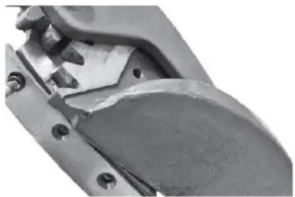
natural_image
Close-up of a mechanical component with bolts and a curved metallic part (no visible text or symbols)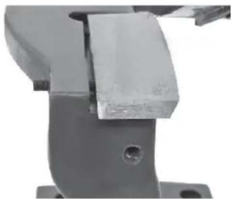
natural_image
Close-up of a mechanical component with a metallic bracket and mounting holes (no visible text or symbols)Figure 7 Figure 8
LOWER BLADE
Removal
- Remove Handle.

WARNING : Handle MUST be removed prior to blade rem reduce the chance of blade accidentally falling.
-
Loosen the bolt #10 securing the Lower Blade Clamp #9 (Figure 8) at the front of the tool.
-
Carefully remove Blade.
Installation
- Replace blade and exert slight pressure against adjusting screws.
- Tighten Lower Blade Clamp bolt.
NOTE: Blade replacement normally requires a re-adjustment of the lower blade due to blade manufacturing tolerance variations. Adjust per Blade Adjustment procedure.
Maintenance
NOTE: Maintenance should be performed before each use.
- Lower the Upper Blade assembly, insert the Locking Pin through both the Blade Housing and the Body in the CLOSED position (Figure 1) and Remove Handle.
- Apply a thin film of light oil or rust-preventive to all bare steel areas.
- Store in a clean, dust-free, dry, dampness free area preferably covered with plastic sheeting.
- Check tightness of all hardware.
- Check operation for binding. Lubricate pivot points and gears periodically with medium bodied lubricating oil.
- Inspect Blades for cracks, damage or premature wear. Replace if damaged
- Clean dirt and debris from Shear Deck.
Trouble Shooting
| PROBLEM | CAUSE | CORRECTION |
| Produces a Rough, Jagged Cut or Fails to Cut. | Worn Blades | Replace Blades. |
| Material Too Thick | Refer to Maximum Material Specs. | |
| Blades out of Adjustment | Follow Adjustment Procedure. |
Drawing
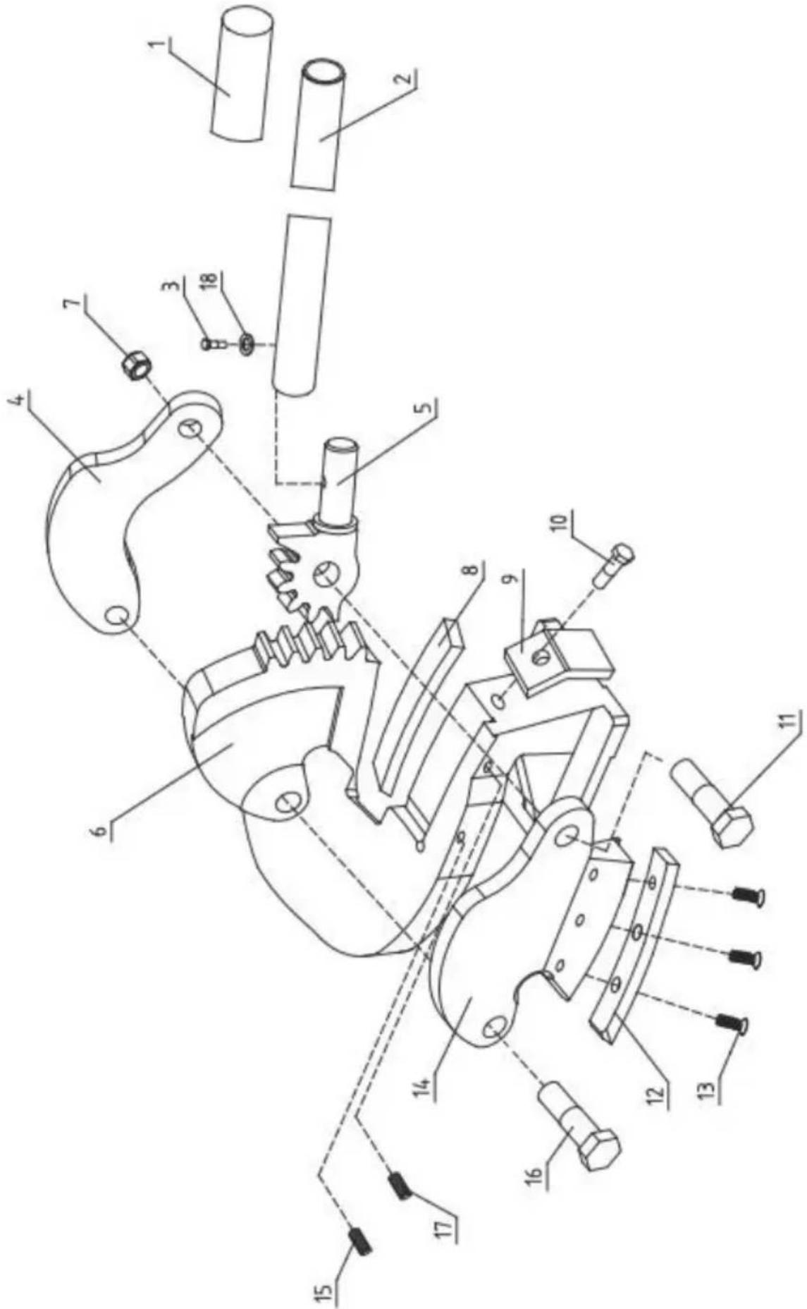
Parts List
| Ref.No. | Description | QTY. |
| 1 | Handle Grip | 1 |
| 2 | Handle | 1 |
| 3 | Bolt M8X20 | 1 |
| 4 | Connecting Arm | 1 |
| 5 | Handle Stub | 1 |
| 6 | Base | 1 |
| 7 | Locknut M12 | 1 |
| 8 | Lower Blade | 1 |
| 9 | Lower Blade Clamp | 1 |
| 10 | Bolt M8X30 | 1 |
| 11 | Bolt M12X45 | 1 |
| 12 | Upper Blade | 1 |
| 13 | Bolt M5X12 | 3 |
| 14 | Holder of Upper Dies | 1 |
| 15 | Screw M5X35 | 1 |
| 16 | Bolt M12X40 | 1 |
| 17 | Screw M5X25 | 1 |
| 18 | Washer 8 | 1 |
Manufacturer: Shanghaimuxinmuyeyouxiangongsi
Address: Shuangchenglu 803nong11hao1602A-1609shi, baoshanqu, shanghai 200000 CN.
Imported to AUS: SIHAO PTY LTD. 1 ROKEVA STREETEASTWOOD NSW 2122 Australia
Imported to USA: Sanven Technology Ltd. Suite 250, 9166 Anaheim Place, Rancho Cucamonga, CA 91730
| UK | REP |
YH CONSULTING LIMITED. C/O YH Consultin Limited Office 147, Centurion House, London Road, Staines-upon-Thames, Surrey, TW18 4A>
| EC | REP |
Affordable. Reliable. Home Improvement.
Cisaille à tôle
MODÈLE : MMS4
VEVOR
Affordable. Reliable. Home Improvement.
Cisaille àtôle
MODÈLE : MMS4

natural_image
Black industrial machine tool with a curved base and lever handle (no visible text or symbols)natural_image
Mechanical tool with lever mechanism (no visible text or symbols)Modèle....MMS-4
natural_image
Close-up of a mechanical tool with a metallic handle and lever mechanism (no visible text or symbols)Figure 1

natural_image
Close-up of a mechanical lever assembly with a cylindrical shaft and flanged lever (no text or symbols visible)Figure 2
natural_image
Close-up of a mechanical component with a metallic tool inserted, showing no visible text or symbols.Figure 3
POUR AJUSTER
natural_image
Close-up of a mechanical component with a threaded rod and bracket (no visible text or symbols)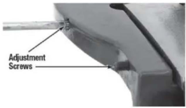
Figure 4 Figure 5 2.
natural_image
Close-up of a mechanical component with bolts and a curved blade (no visible text or symbols)
natural_image
Close-up of a mechanical component with a metallic bracket and mounting holes (no visible text or symbols)Figure Figure 87
LAME INFÉRIEURE
Suppression
- Retirez la poignée.

Technology Ltd. Suite 250, 9166 Anaheim Place, Rancho Cucamonga91730
YH CONSULTING LIMITED. A/S YH Consulting Limited, bureau 147, Centurion House, London Road, Staines-upon-Thames, Surrey, TW18 4AX
E-CrossStu GmbH
Mainzer Landstr.69,
Affordable. Reliable. Home Improvement.
Blechschere
MODELL:MMS4
VEVOR
Affordable. Reliable. Home Improvement.
Blechschere
MODELL: MMS4
natural_image
Black industrial machine tool with a curved base and lever handle (no visible text or symbols)natural_image
Mechanical tool with lever mechanism (no visible text or symbols)Modell......MMS-4
Breite....2,76" (70mm)
Wichtig
natural_image
Close-up of two mechanical tools or clamps, one with a handle and the other with a bracket (no visible text or symbols)natural_image
Close-up of a mechanical component with a metallic tool inserted, showing a curved surface and a small cutout (no visible text or symbols)Abbildung 3
ANPASSEN
natural_image
Close-up of a mechanical component with a threaded rod and bracket (no visible text or symbols)Abbildung 4

Abbildung 5
natural_image
Close-up of a mechanical component with bolts and a curved blade (no visible text or symbols)Abbildung 7

natural_image
Close-up of a mechanical component with a metallic bracket and mounting holes (no visible text or symbols)Abbildung 8
UNTERES KLINGE
Entfernung
- Griffentfernen.

Teileliste
YH CONSULTING LIMITED. C/O YH Consulting Limited,
Büro 147, Centurion House, London Road, Staines-upon-
Thames, Surrey, TW18 4AX
E-CrossStu GmbH
Mainzer Landstr.69,
60329 Frankfurt am Main.

VEVOR
Affordable. Reliable. Home Improvement.
Cesoia per lamiere
MODELLO: MMS4
VEVOR
Affordable. Reliable. Home Improvement.
Cesoia perlamiere
MODELLO: MMS4

natural_image
Black industrial machine tool with a curved base and lever mechanism (no visible text or symbols)natural_image
Mechanical tool with lever and base mount (no visible text or symbols)Modello....MMS-4
natural_image
Close-up of two mechanical tools or clamps, one with a handle and the other with a bracket (no visible text or symbols)Figura Figura 21
natural_image
Close-up of a mechanical component with a metallic tool inserted, showing a curved surface and a small cutout (no visible text or symbols)Figura 3
PER REGOLARE
natural_image
Close-up of a mechanical component with a threaded rod and bracket (no visible text or symbols)Figura 4
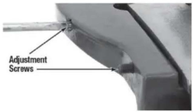
Figura 5 2.
natural_image
Close-up of a mechanical component with bolts and a curved blade (no visible text or symbols)7

natural_image
Close-up of a mechanical component with a metallic bracket and mounting holes (no visible text or symbols)Figura 8Figura
LAMA INFERIORE
Rimozione
Importato in AUS: SIHAO PTY LTD. 1 ROKEVA STREETEASTWOOD NSW 2122
YH CONSULTING LIMITED. C/O YH Consulting Limited
Ufficio 147, Centurion House, London Road, Staines-
upon-Thames, Surrey, TW18 4AX
Affordable. Reliable. Home Improvement.
Affordable. Reliable. Home Improvement.
natural_image
Black industrial machine tool with a curved base and lever handle (no visible text or symbols)natural_image
Mechanical tool with lever and base mount (no visible text or symbols)Modelo....MMS-4
Ancho....2,76" (70mm)
Importante
natural_image
Close-up of a mechanical tool with a metallic handle and lever mechanism (no visible text or symbols)Figura 1

natural_image
Close-up of a mechanical lever assembly with a cylindrical shaft and flanged lever (no text or symbols visible)Figura 2
natural_image
Close-up of a mechanical component with a metallic tool inserted, showing a curved surface and a small inset view (no text or symbols visible)Figura 3
PARA AJUSTAR
natural_image
Close-up of a mechanical component with a threaded rod and bracket (no visible text or symbols)Figura 4

Figura 52.
natural_image
Close-up of a mechanical tool or bracket component with bolts and a curved handle (no visible text or symbols)Figura 7
natural_image
Close-up of a mechanical clamp or bracket component with a metallic block and mounting holes (no visible text or symbols)Figura 8
HOJA INFERIOR
Eliminación
- Retire el mango.

| Ref.No. | Descripción | CANTIDAD. |
| 1 | Empuñadura | 1 |
| 2 | Manejar | 1 |
| 3 | Perno M8X20 | 1 |
| 4 | Brazo deconexión | 1 |
| 5 | Mango detocón | 1 |
| 6 | Base | 1 |
| 7 | Contratuerca M12 | 1 |
| 8 | Hoja inferior | 1 |
| 9 | Abrazadera de la cuchilla inferior | 1 |
| 10 | Perno M8X30 | 1 |
| 11 | Perno M12X45 | 1 |
| 12 | Hoja superior | 1 |
| 13 | Perno M5X12 | 3 |
| 14 | Titular de matrices superiores | 1 |
| 15 | Tornillo M5X35 | 1 |
| 16 | Perno M12X40 | 1 |
| 17 | Tornillo M5X25 | 1 |
| 18 | Lavadora 8 | 1 |
YH CONSULTING LIMITADA. A/C YH Consulting Limited
Oficina 147, Centurion House, London Road, Stainesupon-Thames, Surrey, TW18 4AX
Affordable. Reliable. Home Improvement.
Nożyce do blachy
MODEL: MMS4
VEVOR
Affordable. Reliable. Home Improvement.
Nożyce doblachy
MODEL: MMS4

natural_image
Black industrial machine tool with a curved base and lever handle (no visible text or symbols)natural_image
Mechanical tool with lever and bracket (no visible text or symbols)Model......MMS-4
natural_image
Close-up of a mechanical tool with a metallic handle and lever mechanism (no visible text or symbols)Rysunek 1

natural_image
Close-up of a mechanical lever assembly with a cylindrical shaft and flanged lever (no text or symbols visible)Rysunek 2
natural_image
Close-up of a mechanical component with a metallic tool inserted, showing a curved surface and a small inset view (no text or symbols visible)Rysunek 3
DO DOSTOSOWANIA
natural_image
Close-up of a mechanical bracket with a bolt and clamped spring (no visible text or symbols)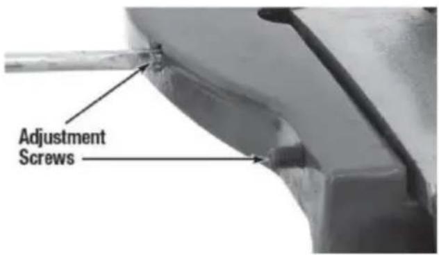
natural_image
Close-up of a mechanical component with bolts and a curved blade (no visible text or symbols)Rysunek 7

natural_image
Close-up of a mechanical component with a metallic bracket and mounting holes (no visible text or symbols)Rysunek 8
DOLNE OSTRZE
Usuwanie
- Zdejmij uchwyt.

Lista części
YH CONSULTING LIMITED. C/O YH Consulting Limited Biuro
147, Centurion House, London Road, Staines-upon-
Thames, Surrey, TW18 4AX
| Przedstawiciel WE |
E-CrossStu GmbH
Mainzer Landstr.69,
60329 Frankfurt nad Menem.

VEVOR
Affordable. Reliable. Home Improvement.
Affordable. Reliable. Home Improvement.
natural_image
Black industrial machine tool with a curved base and lever handle (no visible text or symbols)natural_image
Mechanical tool with lever mechanism (no visible text or symbols)Model......MMS-4
natural_image
Close-up of a mechanical tool with a metallic handle and lever mechanism (no visible text or symbols)Figuur 1
natural_image
Close-up of a mechanical lever assembly with a cylindrical shaft and flanged lever (no text or symbols visible)Figuur 2
natural_image
Close-up of a mechanical component with a metallic tool inserted, showing a curved surface and a small cutout (no visible text or symbols)Figuur 3
AANPASSEN
natural_image
Close-up of a mechanical component with a threaded rod and bracket (no visible text or symbols)Figuur 4

Figuur 5
natural_image
Close-up of a mechanical component with bolts and a curved blade (no visible text or symbols)7

natural_image
Close-up of a mechanical component with a metallic bracket and mounting holes (no visible text or symbols)Figuur 8 Figuur
ONDERSTE MES
Verwijdering
Onderdelenlijst
| Referentienr. | Beschrijving | AANTAL |
| 1 | Handvatgreep | 1 |
| 2 | Hendel | 1 |
| 3 | Bout M8X20 | 1 |
| 4 | Verbindingsarm | 1 |
| 5 | Handvat stomp | 1 |
| 6 | Baseren | 1 |
| 7 | Borgmoer M12 | 1 |
| 8 | Onderste mes | 1 |
| 9 | Onderste bladklem | 1 |
| 10 | Bout M8X30 | 1 |
| 11 | Bout M12X45 | 1 |
| 12 | Bovenblad | 1 |
| 13 | Bout M5X12 | 3 |
| 14 | Houder van bovenmatrijzen | 1 |
| 15 | Schroef M5X35 | 1 |
| 16 | Bout M12X40 | 1 |
| 17 | Schroef M5X25 | 1 |
| 18 | Ring 8 | 1 |
Fabrikant: Shanghaimuxinmuyeyouxiangongsi Adres:
Shuangchenglu 803nong11hao1602A-1609shi, baoshanqu, shanghai 2000CN.
YH CONSULTING LIMITED. T.a.v. YH Consulting Limited
Kantoor 147, Centurion House, London Road, Stainesupon-Thames, Surrey, TW18 4AX
| EC | REP |
E-CrossStu GmbH
Mainzer Landstr.69,
60329 Frankfurt am Main.

VEVOR
Affordable. Reliable. Home Improvement.
Plåtsax
MODELL: MMS4
VEVOR
Affordable. Reliable. Home Improvement.
Plåtsax
MODELL: MMS4

natural_image
Black industrial machine tool with a curved base and lever handle (no visible text or symbols)natural_image
Mechanical tool with lever and base mount (no visible text or symbols)Modell......MMS-4
Max. kapacitet Mjukt stål.....14 Ga. (2,0 mm)
Max. kapacitet rostfritt stål.....18 Ga. (1,2 mm)
Bredd....70 mm
Viktig
natural_image
Close-up of a mechanical tool with a metallic handle and lever mechanism (no visible text or symbols)Figur 1
natural_image
Close-up of a mechanical lever assembly with a cylindrical shaft and flanged lever (no text or symbols visible)Figur 2
natural_image
Close-up of a mechanical component with a metallic tool inserted, showing a curved surface and a small cutout (no visible text or symbols)Figur 3
ATT JUSTERA
natural_image
Close-up of a mechanical component with a bolt and bracket (no visible text or symbols)4

Figur 5 2. Figur
natural_image
Close-up of a mechanical component with bolts and a curved blade (no visible text or symbols)Figur 7
natural_image
Close-up of a mechanical component with a metallic bracket and mounting holes (no visible text or symbols)Figur 8
NEDRE BLAD
Borttagning
- Ta bort handtaget.

Dellista
| Ref.nr. | Beskrivning | ANTAL |
| 1 | Handtagsgrepp | 1 |
| 2 | Hantera | 1 |
| 3 | Bult M8X20 | 1 |
| 4 | Anslutningsarm | 1 |
| 5 | Handtagstub | 1 |
| 6 | Bas | 1 |
| 7 | Låsmutter M12 | 1 |
| 8 | Nedre blad | 1 |
| 9 | Nedre bladklämma | 1 |
| 10 | Bult M8X30 | 1 |
| 11 | Bult M12X45 | 1 |
| 12 | Övre blad | 1 |
| 13 | Bult M5X12 | 3 |
| 14 | Innehavare av övre matriser | 1 |
| 15 | Skruv M5X35 | 1 |
| 16 | Bult M12X40 | 1 |
| 17 | Skruv M5X25 | 1 |
| 18 | Bricka 8 | 1 |
Tillverkare: Shanghaimuxinmuyeyouxiangongsi Adress:
Shuangchenglu 803nong11hao1602A-1609shi, baoshanqu, shanghai 2000CN.
Importerad till Australien: SIHAO PTY LTD. 1 ROKEVA STREETEASTWOOD NSW 2122 Australien
Importerad till USA: Sanven Technology Ltd. Suite 250, 9166 Anaheim Place, Rancho Cucamonga, CA 91730
YH CONSULTING LIMITED. C/O YH Consulting Limited
Kontor 147, Centurion House, London Road, Staines-upon-Thames, Surrey, TW18 4AX
| EG-representant |
E-CrossStu GmbH
Mainzer Landstr.69,
60329 Frankfurt am Main.