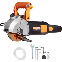
KC133 - Saw Vevor - Free user manual and instructions
Find the device manual for free KC133 Vevor in PDF.


| Product Type | Concrete Saw |
| Brand | Vevor |
| Model | KC133 |
| Power Supply Voltage | 220-240 V AC |
| Frequency | 50/60 Hz |
| Rated Power | 2500 W |
| Max Power | 5800 W |
| No-Load Speed | 6500 rpm |
| Blade Diameter | 133 mm |
| Blade Bore | 20 mm |
| Blade Thickness | 4.2 mm |
| Max Cutting Capacity (Depth x Width) | 41 x 42 mm |
| Auxiliary Handle | Yes, rotatable 360° |
| Water Supply | Built-in water pump for wet cutting |
| Leak Protection | Leak-proof plug |
| Dust Prevention System | Compatible with vacuum cleaner |
| Recommended Use | Cutting brick, concrete, granite, marble, tiles |
| Safety | Eye protection, ear protection, and dust mask recommended |
| Maintenance | Regular cleaning of air vents and carbon brushes |
| Spare Parts | Saw blades, carbon brushes, sealing gaskets |
Frequently Asked Questions - KC133 Vevor
User questions about KC133 Vevor
0 question about this device. Answer the ones you know or ask your own.
Ask a new question about this device
Download the instructions for your Saw in PDF format for free! Find your manual KC133 - Vevor and take your electronic device back in hand. On this page are published all the documents necessary for the use of your device. KC133 by Vevor.
USER MANUAL KC133 Vevor
Technical Support and E-Warranty Certificate www.vevor.com/support
CONCRETE SAW
OWNER'S MANUAL
MODEL: KC133/KC160/KC125
We continue to be committed to provide you tools with competitive price. "Save Half", "Half Price" or any other similar expressions used by us only represent of savings you might benefit from buying certain tools with us compared top brands and doses not necessarily mean to cover all categories of tools offered are kindly reminded to verify carefully when you are placing an order with us actually saving half in comparison with the top major brands.
VEVOR®
CONCRETE SAW
MODEL: KC133/KC160/KC125
natural_image
Black and white photo of a power tool with visible blades and buttons (no text or symbols)NEED HELP? CONTACT US!
Have product questions? Need technical support? Please feel from contact us:
Technical Support and E-Warranty Certificate www.vevor.com/support
This is the original instruction, please read all manual instruction carefully before operating. VEVOR reserves a clear interpretation user manual. The appearance of the product shall be subject to product you received. Please forgive us that we won't inform you there are any technology or software updates on our product.
Sincerely thank you for choosing our products, you will get the compa comprehensive technical support and service guarantee.
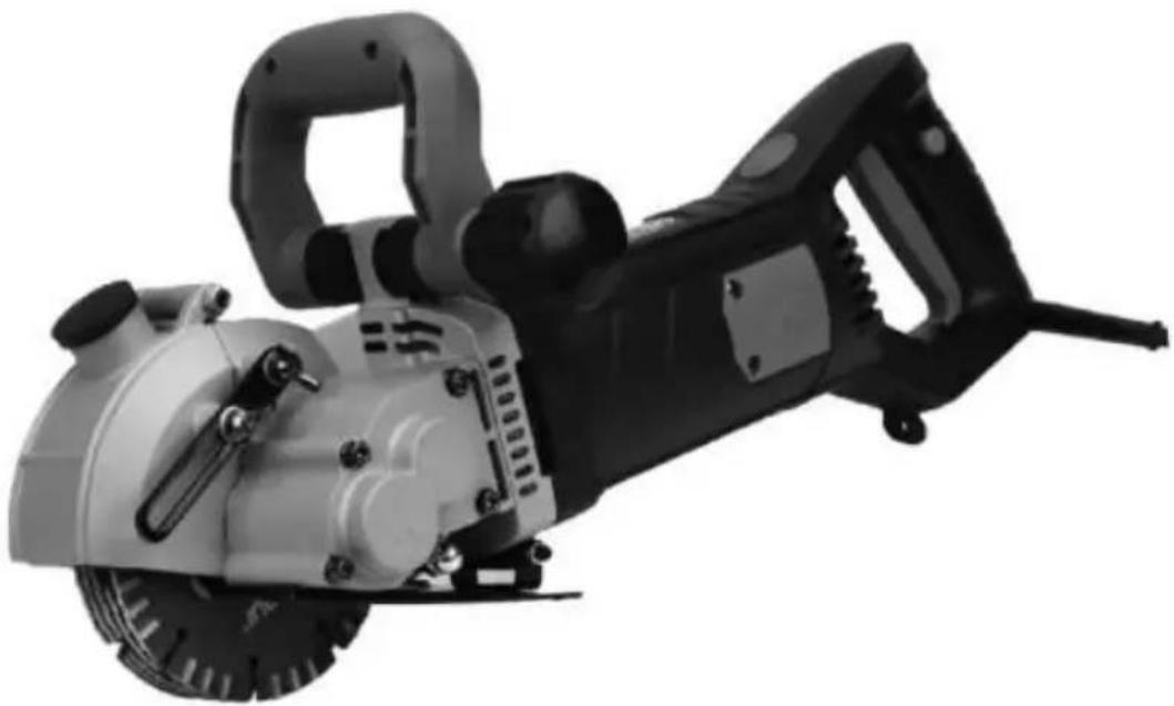
Product Description: This tool is suitable for the cutting and forming of fire brick, cement brick, light brick, concrete wall (ground) and the cut granite, marble, ceramic tile and other building materials.
The product, compared with previous products has the following salien features.
- Under the same efficiency, the weight is lighter than the previous products, greatly reducing the user's labor intensity. However, the depth the groove is deeper and wider than the previous ones.
- Rotatable auxiliary handle, more suitable for the use of a variety of complex places.
- Maintenance is faster and more convenient.
4, Unique leak-proof design enhances the service life of the machine greatly, making it much safer to operate. - The design of rotatable rear handle is safer and more ergonomic.
6.75-360 degrees arbitrarily cut, competent for all complex places to u - This tool is designed for water and vacuum with two in one oper structure, greatly reducing the dust of cutting operations. With water operations can effectively extend the life of the blade, thereby reducing cost of slotting.
- Equipped with a pump and leakage protection plugs make slotting e and safer.
- Equipped with clamshell shield, can effectively protect the gravel, d on the human injury.Completely avoid the traditional slotted machine sl was crushed sand and sedimentary defects.
PARAMETER
| Model | KC133 | KC160 | KC125 | |
| Voltage Frequency | AC220-240V 50Hz | AC120V 60Hz | AC120V 60Hz | AC220-24 0V 50Hz |
| Rated Power | 2500W | 2500W | 2500W | 2500W |
| Max Power | 6200W | 5800W | 4800W | 4800W |
| Speed of revolution | 6500r/min | 6800r/min | 6800r/min | 6500r/min |
| Saw blade specification | ∅ 133*∅ 20*4.2 mm | ∅ 160*∅ 22.2* 2.5mm | ∅ 125*∅ 20*2.5mm | |
| Most cutting capacity(D* W) | 41*42mm | 50*38mm | 34*42mm | |
SYMBOL INSTRUCTIONS

Warning symbol means any failure to follow the operating
procedures in this manual will result in personal injury or damage to machine.
Prevent electric shock symbol, means that any operation not in
accordance with the operating procedures in this manual, will cause electric shock damage.
Fire symbol means any failure to follow the operating instruction
this manual will result in fire hazard.
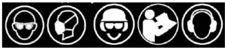
natural_image
Five circular icons representing different occupational and safety symbols (no text or labels)The eye protection symbol may be modified by adding other personal protective equipment such as ear protection, dust mask, etc.
WARNING
To reduce the risk of injury, use only accessories rated at least equal maximum speed marked on the tool.
General Safety Rules
WARNING! Read all safety warnings and all instructions. Failure to fo the warnings and instructions may result in electric shock, fire and/or serious injury. Save all warnings and instructions for future reference. term "power tool" in all of the warnings listed below refers to your mains-operated (corded) power tool or battery-operated (cordless) power tool.
1) Work area safety
a) Keep work area clean and well lit. Cluttered or dark areas invite accidents.
b) Do not operate power tools in explosive atmospheres, such as in presence of flammable liquids, gases or dust. Power tools create spar which may ignite the dust or fumes.
c) Keep children and bystanders away while operating a power tool. Distractions can cause you to lose control.
2) Electrical safety
a) Power tool plugs must match the outlet. Never modify the plug in way.
Do not use any adapter plugs with earthed (grounded) power tools. Unmodified plugs and matching outlets will reduce risk of electric shock b) Avoid body contact with earthed or grounded surfaces, such as pip radiators, ranges and refrigerators. There is an increased risk of electric shock if your body is earthed or grounded.
c) Do not expose power tools to rain or wet conditions. Water enteri
power tool will increase the risk of electric shock.
d) Do not abuse the cord. Never use the cord for carrying, pulling or unplugging the power tool. Keep cord away from heat, oil, sharp edge moving parts. Damaged or entangled cords increase the risk of electric shock.
e) When operating a power tool outdoors, use an extension cord suit for outdoor use. Use of a cord suitable for outdoor use reduces the electric shock.
f) If operating a power tool in a damp location is unavoidable, use a fault circuit interrupter (GFCI) protected supply. Use of an GFCI reduces the risk of electric shock.
3) Personal safety
a) Stay alert, watch what you are doing and use common sense who operating a power tool. Do not use a power tool while you are tired under the influence of drugs, alcohol or medication. A moment of inattention while operating power tools may result in serious personal injury.
b) Use personal protective equipment. Always wear eye protection. Protective equipment such as dust mask, non-skid safety shoes, hard or hearing protection used for appropriate conditions will reduce person injuries.
c) Prevent unintentional starting. Ensure the switch is in the off-position before connecting to power source and/or battery pack, picking up or carrying the tool. Carrying power tools with your finger on the switch energising power tools that have the switch on invites accidents.
d) Remove any adjusting key or wrench before turning the power too wrench or a key left attached to a rotating part of the power tool m in personal injury.
e) Do not overreach. Keep proper footing and balance at all times. 7 enables better control of the power tool in unexpected situations.
f) Dress properly. Do not wear loose clothing or jewellery. Keep your clothing and gloves away from moving parts. Loose clothes, jewellery
©
tool is maintained.
Special requirement for cutting off tool.
6) Cut-off machine safety warnings
a) The guard provided with the tool must be securely attached to the tool and positioned for maximum safety, so the least amount of saw is exposed towards the operator.
Position yourself and bystanders away from the plane of the rotating blade.
The guard helps to protect operator from broken wheel fragments and accidental contact with saw blade.
b) Use only bonded reinforced or diamond cut-off saw blades for your power tool. Just because an accessory can be attached to your power it does not assure safe operation.
c) The rated speed of the accessory must be at least equal to the maximum speed
marked on the power tool. Accessories running faster than their rated speed can break and fly apart.
d) Saw blades must be used only for recommended applications. For example: do not grind with the side of cut-off saw blade. Abrasive cut wheels are intended for peripheral grinding, side forces applied to these wheels may cause them to shatter.
e) Always use undamaged saw blade flanges that are of correct diameter for your selected saw blade. Proper saw blade flanges support the saw blade thus reducing the possibility of saw blade breakage.
f) Do not use worn down reinforced wheels from larger power tools. blades intended for a larger power tool are not suitable for the higher speed of a smaller tool and may burst.
NOTE The above warning does not apply for tools only designated to used with diamond wheels.
g) The outside diameter and the thickness of your accessory must be
©
m) Position the cord clear of the spinning accessory. If you lose con cord may be cut or snagged and your hand or arm may be pulled spinning saw blade.
n) Never lay the power tool down until the accessory has come to a complete stop. The spinning wheel may grab the surface and pull the power tool out of your control.
o) Do not run the power tool while carrying it at your side. Accident contact with the spinning accessory could snag your clothing, pulling t accessory into your body.
p) Regularly clean the power tool's air vents. The motor's fan will drain dust inside the housing and excessive accumulation of powdered metal may cause electrical hazards.
q) Do not operate the power tool near the flammable materials. Spark could ignite these materials.
r) Do not use accessories that require liquid coolants. Using water or liquid coolants may result in electrocution or shock.
FURTHER SAFETY INSTRUCTIONS FOR ABRASIVE
CUTTING-OFF OPERATIONS
Kickback and related warnings
Kickback is a sudden reaction to a pinched or snagged rotating saw Pinching or snagging causes rapid stalling of the rotating wheel which turn causes the uncontrolled power tool to be forced in the direction opposite of the saw blade's rotation at the point of the binding.
For example, if an abrasive saw blade is snagged or pinched by the piece, the edge of the wheel that is entering into the pinch point can into the surface of the material causing the saw blade to climb out. The saw blade may either jump toward or away from the operation depending on direction of the saw blade's movement at the point of pinching. Abrasive saw blades may also break under these conditions.
Kickback is the result of power tool misuse and/or incorrect operating procedures or conditions and can be avoided by taking proper precau as given below.
a) Maintain a firm grip on the power tool and position your body an allow you to resist kickback forces. Always use auxiliary handle, if pro for maximum control over kickback or torque reaction during start-up. operator can control torque reactions or kickback forces, if proper precautions are taken.
b) Never place your hand near the rotating accessory. Accessory may kickback over your hand.
c) Do not position your body in line with the rotating wheel. Kickback propel the tool in direction opposite to the wheel's movement at the snagging.
d) Use special care when working corners, sharp edges etc. Avoid bouncing and
snagging the accessory. Corners, sharp edges or bouncing have a tendency to snag the rotating accessory and cause loss of control or kickback.
e) Do not attach a saw chain, woodcarving blade, segmented diamond wheel with a peripheral gap greater than 10 mm or toothed saw blade. Such blades create frequent kickback and loss of control.
f) Do not "jam" the wheel or apply excessive pressure. Do not attempt make an
excessive depth of cut. Over stressing the wheel increases the loading susceptibility to twisting or binding of the wheel in the cut and the p of kickback or saw blade breakage.
g) When wheel is binding or when interrupting a cut for any reason, off the power tool and hold the power tool motionless until the wheel to a complete stop. Never attempt to remove the wheel from the cut the wheel is in motion otherwise kickback may occur. Investigate and corrective action to eliminate the cause of saw blade binding.
h) Do not restart the cutting operation in the work-piece. Let the saw blade reach full speed and carefully re-enter the cut. The saw blade may be walk up or kickback if the power tool is restarted in the work-piece. i) Support panels or any oversized work-piece to minimize the risk of blade pinching and kickback. Large work-pieces tend to sag under the own weight. Supports must be placed under the work-piece near the cut and near the edge of the work-piece on both sides of the saw j) Use extra caution when making a “pocket cut” into existing walls of blind areas.
The protruding wheel may cut gas or water pipes, electrical wiring or objects that can cause kickback.
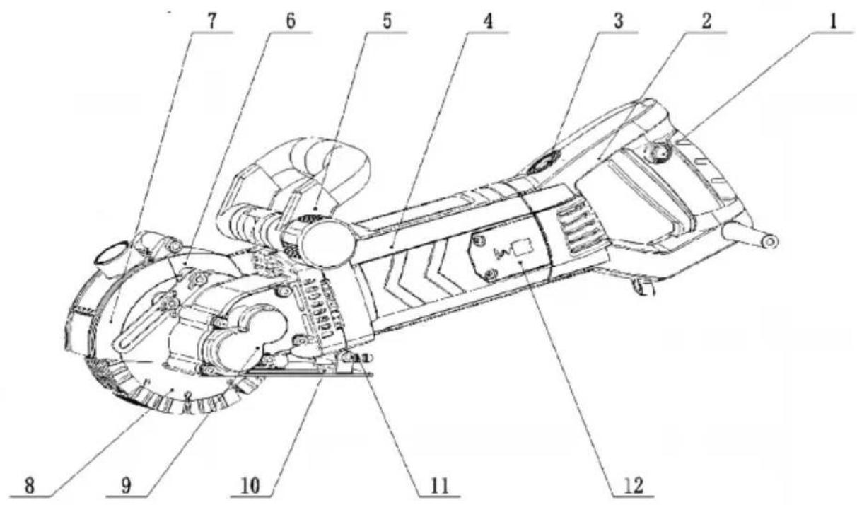
NAME OF THE COMPONENT
| 1 switch; | 5 front handle | 9 bearing |
| 2 handle cover | 6 Aluminum head sh | 10 base plate |
| 3 rotary button | 7 movable shield | 11 faucet |
| 4 chassis | 8 saw blade | 12 brush cover |
SAFE OPERATION INSTRUCTIONS
Working environment
1) The work area should be clean, light and well-ventilated.
2) Do not use this machine in places with inflammable and explosive materials.
3) When the machine is working, be sure to keep away from children bystanders and animals.
4) Do not use the power cord to pull the machine. Otherwise, it may be damaged and cannot.
work properly.
1) The machine uses the leakage protection plug, please use the plu the warning label requirements
2) The socket type of the power supply should be matched with the provided by this machine. It is not allowed to make any change to the structure, and use this machine under the condition of power supply grounding wire.
3) Do not use this machine outdoors in the rainy day.
4) Do not use the power cord to pull the machine, so as to avoid machine is not good and cannot work properly
5) We should avoid the power cord contact with hot, wet, sharp clas material and moving parts.
6) When the machine is used outdoors, please use the power cord extending 4mm^2 above and outdoor, and keep the connection reliable.
7) After turning on the machine, avoid any part of the body touching wall surface.
PERSONAL SAFETY
1) When operating the machine, always be on guard and never use machine under conditions of fatigue, alcohol abuse, drugs or medication avoid accidents caused by inattention during operation.
2) When operating, be sure to use protective equipment, such as dust masks, goggles, earmuffs and so on. To avoid splashing sand and dust
contuse eyes and face, or hearing loss due to strong noise.
3) To avoid starting accidentally, make sure the machine's switch is before turning on the power. Ensure the appropriate connection to the power Do not put your finger on the switch button to prevent accident
4) Before starting the machine, check that the adjusting lock wrench tool have been removed from the machine.
5) When operating, the body should not stretch forward too much, please always keep your body balanced.
6) When operating, please do not wear loose clothing, do not wear j users with longer hair should discard hair into the protective caps, so not to touch the moving parts during operation, causing accidents.
THE USE OF THE MACHINE AND PRECAUTIONS
1) Before using, check the safety of the power supply. Poor socket and power cord can cause poor contact. In severe cases, it may cause e shock, fire and other accidents.
2) During the slotting operation, keep the machine straight and advance uniformly.
3) Operators should wear insulated gloves and insulated shoes when water-cut operation,
so as to avoid electric shock accidents.
4) Draw the guide wire on the work surface to improve the efficiency accuracy of slotting.
5) The machine is high-power with heavier work load, so please ensure interconnecting
components solid and reliable before using.
6) Waterless cutting operations should be equipped with dust removal equipment, so as to ensure a good working environment
7) When turning the machine, you should open the cover while payin special attention to the protection of flying sands. Slotting work without protection is very dangerous. In serious cases, it will cause personal
8) When using a pump to groove on the wall, work from top to bottom
careful not to let water flow into the machine.
OPERATION INSTRUCTIONS
| AFacing the slot when operation | |
Side handle forward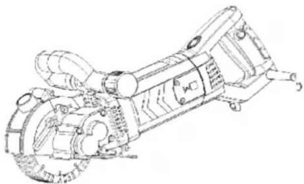 The state of a cover when cover is closed The state of a cover when cover is closed | 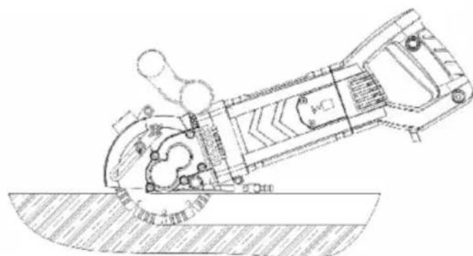 A plane wall for cutting (slotting)the cover is closed A plane wall for cutting (slotting)the cover is closed |
| BWhen the corner slotted operation | |
Unscrew Flipping Side handlethe screw: shield backdrop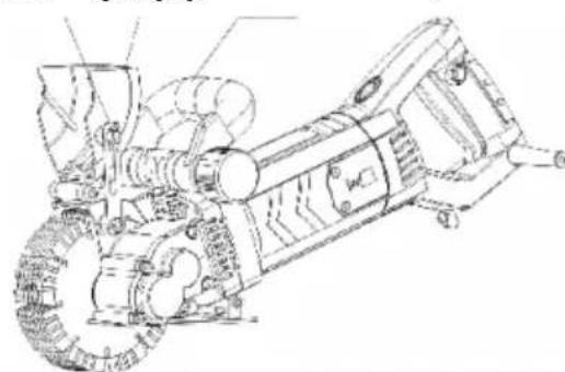 The state of the overturn. The state of the overturn. | 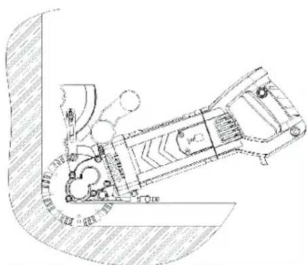 When the cover is turned over,used for cutting (slotting) wall co When the cover is turned over,used for cutting (slotting) wall co |
THE USE OF WATER PUMPS
-
A pipe into the machine on the tap.
-
The other end of the water pipe into the pump outlet.
-
Put the pump into the bucket with water, plug in power and then used.
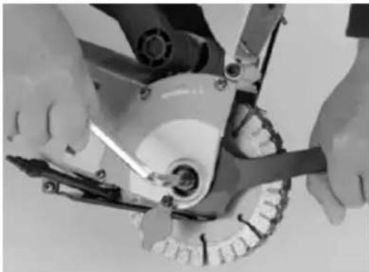
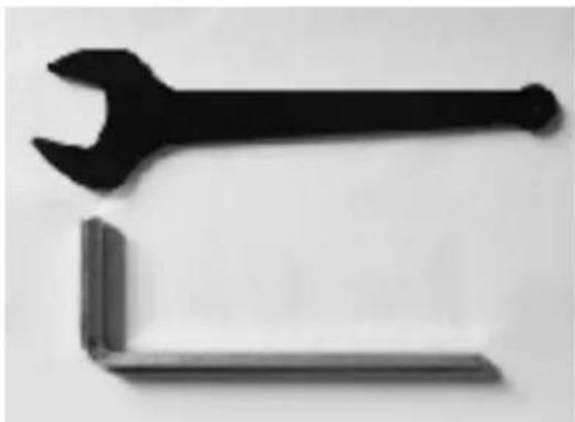
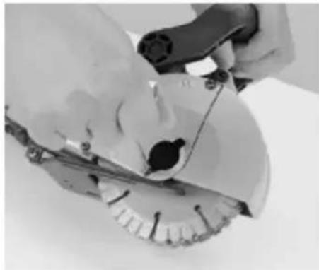
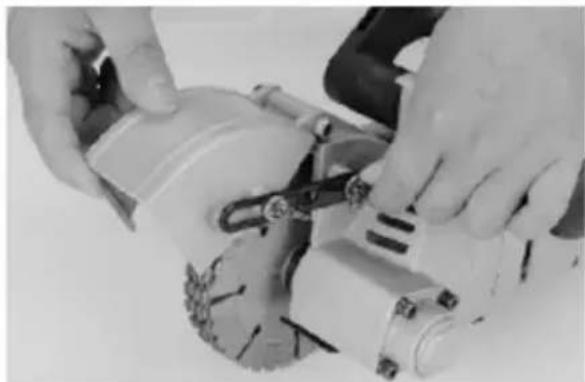
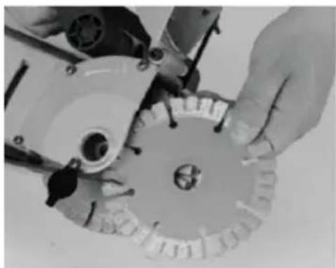
REPLACE THE CUTTING PIECE
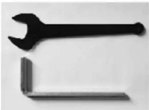
natural_image
Two black wrench and a separate L-shaped tool against a plain background (no text or symbols)- Disassembly tools
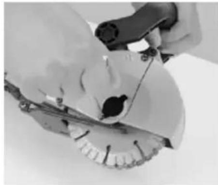
natural_image
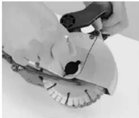
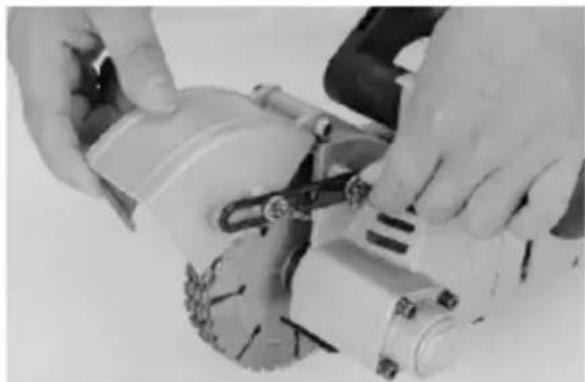
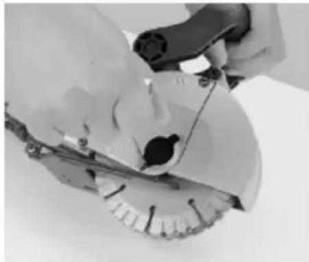
Close-up of hands using a tool to cut or mark a mechanical component (no visible text or symbols)- Open the cover sheet
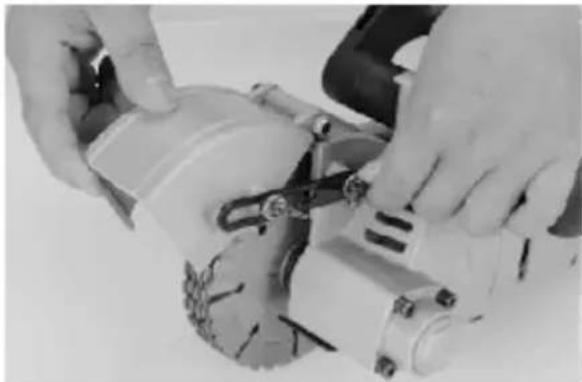
natural_image
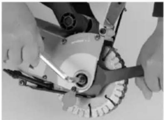
Close-up of hands operating a power tool on a mechanical device (no visible text or symbols)- Loosen the screw and flip the ad shield
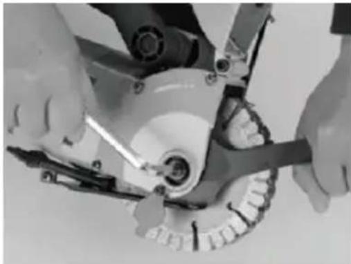
natural_image
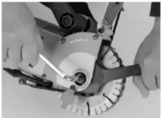
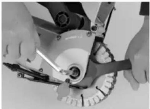
Close-up of hands using a tool to adjust or install a mechanical component (no visible text or symbols)- Unfold counterclockwise
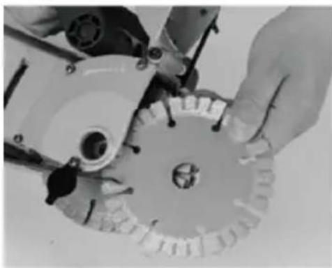
natural_image
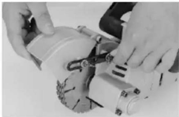
Close-up of hands operating a mechanical gear assembly (no visible text or symbols)- Remove the pressure plate and blade
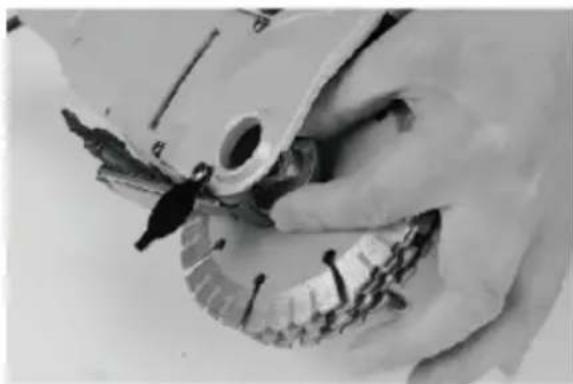
natural_image
Close-up of hands assembling a mechanical component (no visible text or symbols)- Remove the spacer between the s blades
natural_image
Close-up of hands operating a mechanical device with a tool, no visible text or symbols- Remove the order of reverse installation, to complete the replacement. (Lock clockwise)
THE MACHINE'S MAINTENANCE AND REPAIR
Before any maintenance and care of this machine, you must disconnect the power, unplug the plug!
1) The machine is manufactured according to safety standards and shall not be disassembled if the machine fails to work.
2) When repairing, the accessory must be the spare parts provided by company, otherwise the machine will be damaged or hurt.
3) After each use of the machine, be sure to clean the gravel and the machine and keep all operating parts such as switches, plugs an handles clean and keep it out of the reach of children, keep it dry. A on the machine can not work or accident.
MACHINE COMPONENTS DIAGRAM
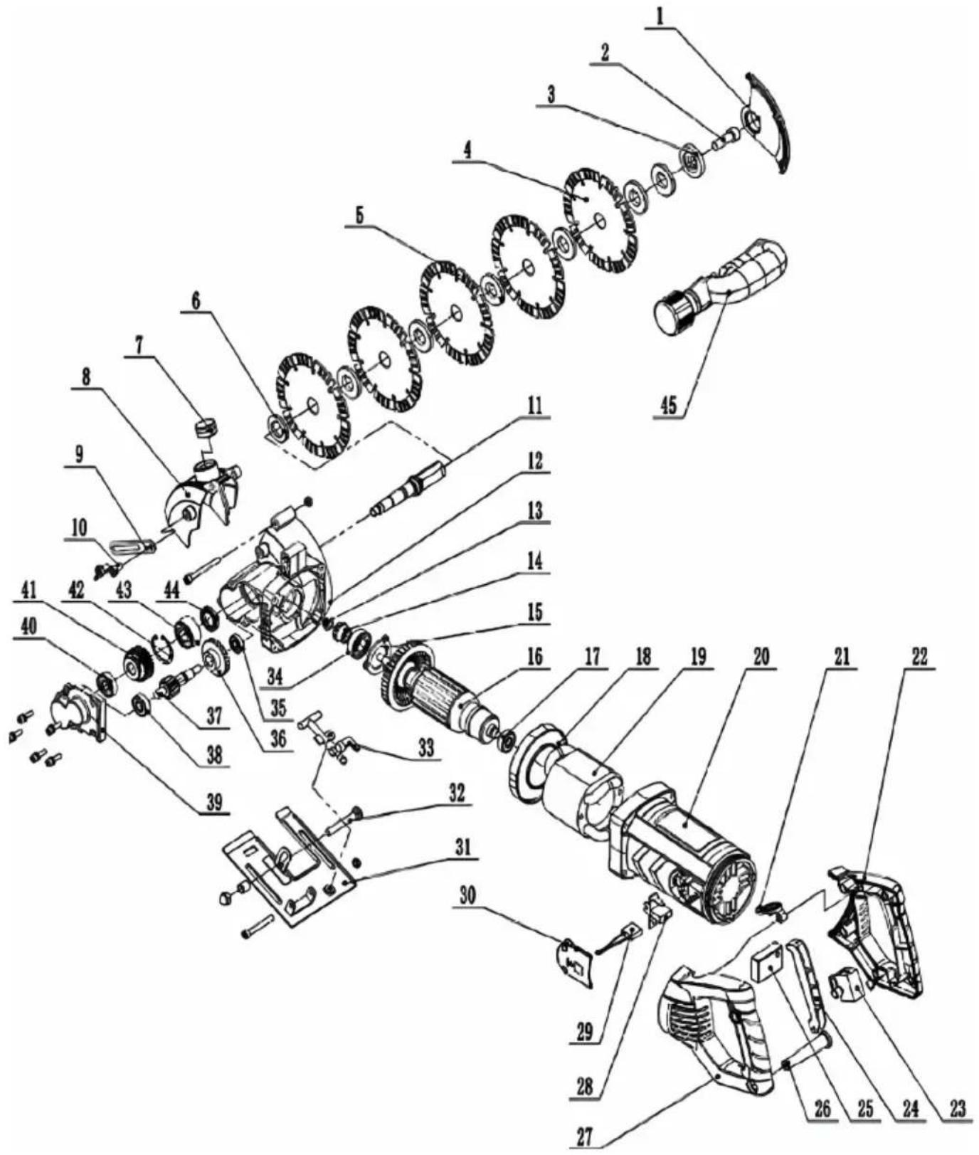
| Index No. | Description | Q'ty | Index No. | Description | Q'ty |
| 1 | Side cover | 1 | 24 | Switch button | 1 |
| 2 | Internal six angle screws M10X25 | 1 | 25 | soft start | 1 |
| 3 | Upper pressure plate | 1 | 26 | Wire sheath | 1 |
| 4 | Saw blade | 5 | 27 | Left handle | 1 |
| 5 | Shim | 7 | 28 | Carbon brush frame | 2 |
| 6 | Lower pressure plate | 1 | 29 | Carbon brush | 2 |
| 7 | Rubber plug | 1 | 30 | Brush holder cover | 2 |
| 8 | Protection cover | 1 | 31 | floor | 1 |
| 9 | Fast limit | 1 | 32 | Carriage screw | 1 |
| 10 | Butterfly screw | 2 | 33 | Water tap | 1 |
| 11 | output shaft | 1 | 34 | Bearing 6202 | 1 |
| 12 | Head | 1 | 35 | Bearing 608 | 1 |
| 13 | Looser nut M8 | 1 | 36 | Large parachute tooth | 1 |
| 14 | Small beach tooth | 1 | 37 | Gear shaft | 1 |
| 15 | press plate | 1 | 38 | Bearing 6000 | 1 |
| 16 | rotor | 1 | 39 | Bearing seat | 1 |
| 17 | Bearing 629 | 1 | 40 | Bearing 6200 | 1 |
| 18 | Guide ring | 1 | 41 | Gear | 1 |
| 19 | Stator | 1 | 42 | Hole gear ring | 1 |
| 20 | Shell | 1 | 43 | Bearing 3202 | 1 |
| 21 | Rotary button | 1 | 44 | Skeleton oil seal | 1 |
| 22 | Right handle | 1 | 45 | Side handle assembly | 1 |
| 23 | switch | 1 |
VEVOR®
TOUGH TOOLS, HALF PRICE
Technical Support and E-Warranty Certificate
www.vevor.com/support
VEVOR®
TOUGH TOOLS, HALF PRICE
natural_image
Black and white photo of a power tool with a flat blade and circular head (no visible text or symbols)natural_image
Five black-and-white icons representing different workplace or safety symbols (no text or labels)INSTRUCTIONS D'UTILISATION SÉCURITAIRE
REEMPLACER LA PIÈCE DE COUPE
natural_image
Two black wrenches placed side by side on a plain background (no text or symbols)- Outils de démontage
natural_image
Close-up of hands using a tool to cut a car brake disc (no visible text or symbols)natural_image
Close-up of hands using a power tool to adjust or install a motor (no visible text or symbols)natural_image
Close-up of hands using a tool to adjust or install a mechanical component (no visible text or symbols)natural_image
Close-up of hands operating a mechanical device with gears and tools (no visible text or symbols)natural_image
Close-up of hands using a tool to adjust or install a mechanical component (no visible text or symbols)6.Retirez l'entretoise entre la scie lames
natural_image
Close-up of hands using a tool to adjust or install a mechanical component (no visible text or symbols)natural_image
Black and white photo of a power tool with a handle and blade, no visible text or symbolsnatural_image
Five black-and-white icons representing different workplace or safety symbols (no text or labels)natural_image
Two black wrenches placed side by side on a plain background (no text or symbols)- Demontagewerkzeuge
natural_image
Close-up of hands using a tool to cut a car brake disc (no visible text or symbols)natural_image
Close-up of hands using a power tool on a mechanical component (no visible text or symbols)natural_image
Close-up of hands using a tool to adjust or install a mechanical component (no visible text or symbols)natural_image
Close-up of hands operating a mechanical device with gears and tools (no visible text or symbols)natural_image
Close-up of hands using a tool to adjust or install a mechanical component (no visible text or symbols)Klingen
natural_image
Close-up of hands using a tool to adjust or install a mechanical component (no visible text or symbols)www.vevor.com/support
VEVOR®
TOUGH TOOLS, HALF PRICE
natural_image
Black and white photo of a power tool with a flat blade and circular head (no visible text or symbols)natural_image
Five black-and-white icons representing different workplace or safety symbols (no text or labels)natural_image
Two black wrenches placed side by side on a plain background (no text or symbols)natural_image
Close-up of hands using a tool to cut a car brake disc (no visible text or symbols)natural_image
Close-up of hands using a power tool to adjust or install a motor (no visible text or symbols)natural_image
Close-up of hands using a tool to adjust or install a mechanical component (no visible text or symbols)natural_image
Close-up of hands operating a mechanical device with a circular component and tools (no visible text or symbols)natural_image
Close-up of hands using a tool to adjust or install a mechanical component (no visible text or symbols)natural_image
Close-up of hands using a tool to adjust or install a mechanical component (no visible text or symbols)elettronica www.vevor.com/support
VEVOR®
TOUGH TOOLS, HALF PRICE
natural_image
Black and white photo of a power tool with a handle and blade, no visible text or symbolsnatural_image
Five black-and-white icons representing different workplace or safety symbols (no text or labels)natural_image
Two black wrenches placed side by side on a plain background (no text or symbols)natural_image
Close-up of hands using a tool to cut a car brake disc (no visible text or symbols)- Abra la portada
natural_image
Close-up of hands using a power tool to adjust or install a motor (no visible text or symbols)natural_image
Close-up of hands using a tool to adjust or install a mechanical component (no visible text or symbols)natural_image
Close-up of hands operating a mechanical device with gears and tools (no visible text or symbols)natural_image
Close-up of hands using a tool to adjust or install a mechanical component (no visible text or symbols)natural_image
Close-up of hands using a tool to adjust or install a mechanical component (no visible text or symbols)natural_image
Black and white photo of a power tool with visible blades and handle (no text or symbols)POTRZEBUJESZ POMOCY? SKONTAKTUJ SIĘ Z NAMI!
natural_image
Five black-and-white icons representing different workplace or safety symbols (no text or labels)INSTRUKCJA BEZPIECZNEJ OBSŁUGI
Środowisko pracy
natural_image
Two black wrenches placed side by side on a plain background (no text or symbols)natural_image
Close-up of hands using a tool to cut a car brake disc (no visible text or symbols)natural_image
Close-up of hands using a power tool to adjust or install a motor (no visible text or symbols)natural_image
Close-up of hands using a tool to adjust or install a mechanical component (no visible text or symbols)natural_image
Close-up of hands assembling a mechanical gear assembly (no visible text or symbols)natural_image
Close-up of hands using a tool to adjust or install a mechanical component (no visible text or symbols)ostrza
natural_image
Close-up of hands using a tool to adjust or install a mechanical component (no visible text or symbols)KONSERWACJA I NAPRAWA MASZYNY
natural_image
Black and white photo of a power tool with a flat blade and circular head (no visible text or symbols)HULP NODIG? NEEM CONTACT MET ONS OP!
natural_image
Five black-and-white icons representing different workplace or safety symbols (no text or labels)VEILIGE BEDIENINGSINSTRUCTIES
Werkomgeving
natural_image
Two black wrenches placed side by side on a plain background (no text or symbols)natural_image
Close-up of hands using a tool to cut a car brake disc (no visible text or symbols)- Open het voorblad
natural_image
Close-up of hands using a power tool on a mechanical component (no visible text or symbols)natural_image
Close-up of hands using a tool to adjust or install a mechanical component (no visible text or symbols)natural_image
Close-up of hands operating a mechanical device with gears and tools (no visible text or symbols)natural_image
Close-up of hands using a tool to adjust or install a mechanical component (no visible text or symbols)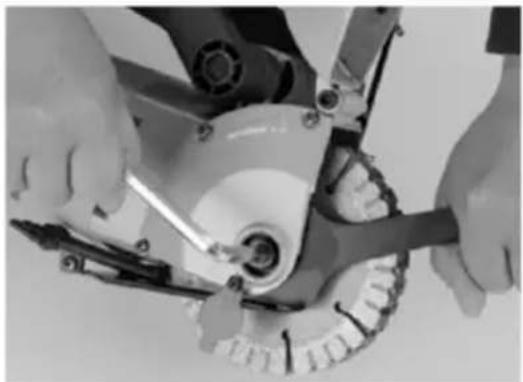
natural_image
Close-up of hands using a tool to adjust or install a mechanical component (no visible text or symbols)garantiecertificaat www.vevor.com/support
VEVOR®
TOUGH TOOLS, HALF PRICE
natural_image
Black and white photo of a power tool with a flat blade and circular head (no visible text or symbols)BEHÖVER HJÄLP? KONTAKTA OSS!
natural_image
Five black-and-white icons representing different workplace or safety symbols (no text or labels)SÄKER ANVÄNDNINGSINSTRUKTIONER
Arbetsmiljö
natural_image
Two black wrenches placed side by side on a plain background (no text or symbols)- Demonteringsverktyg
natural_image
Close-up of hands using a tool to cut a car brake disc (no visible text or symbols)- Öppna omslagsarket
natural_image
Close-up of hands using a power tool on a mechanical component (no visible text or symbols)natural_image
Close-up of hands using a tool to adjust or install a mechanical component (no visible text or symbols)- Vik ut moturs
natural_image
Close-up of hands operating a mechanical device with gears and tools (no visible text or symbols)natural_image
Close-up of hands using a tool to adjust or install a mechanical component (no visible text or symbols)natural_image
Close-up of hands using a tool to adjust or install a mechanical component (no visible text or symbols)www.vevor.com/support

- CONCRETE SAW
- OWNER'S MANUAL
- VEVOR®
- NEED HELP? CONTACT US!
- PARAMETER
- SYMBOL INSTRUCTIONS
- WARNING
- General Safety Rules
- 1) Work area safety
- 2) Electrical safety
- 3) Personal safety
- 6) Cut-off machine safety warnings
- FURTHER SAFETY INSTRUCTIONS FOR ABRASIVE
- CUTTING-OFF OPERATIONS
- Kickback and related warnings
- SAFE OPERATION INSTRUCTIONS
- Working environment
- work properly.
- PERSONAL SAFETY
- THE USE OF THE MACHINE AND PRECAUTIONS
- THE USE OF WATER PUMPS
- REPLACE THE CUTTING PIECE
- THE MACHINE'S MAINTENANCE AND REPAIR
- TOUGH TOOLS, HALF PRICE
- INSTRUCTIONS D'UTILISATION SÉCURITAIRE
- REEMPLACER LA PIÈCE DE COUPE
- INSTRUKCJA BEZPIECZNEJ OBSŁUGI
- Środowisko pracy
- KONSERWACJA I NAPRAWA MASZYNY
- HULP NODIG? NEEM CONTACT MET ONS OP!
- VEILIGE BEDIENINGSINSTRUCTIES
- Werkomgeving
- BEHÖVER HJÄLP? KONTAKTA OSS!
- SÄKER ANVÄNDNINGSINSTRUKTIONER
- Arbetsmiljö
Brand : Vevor
Model : KC133
Category : Saw