LH-18112 - Boat Vevor - Free user manual and instructions
Find the device manual for free LH-18112 Vevor in PDF.

| Brand | Vevor |
| Model | LH-18112 (also LH-18110, LH-18113, LH-18112-1) |
| Product type | Inflatable boat for water sports |
| Use | Private navigation in sheltered waters (coastal areas up to 300 m from shore, small lakes, narrow rivers, canals) |
| Maximum weather conditions | Wind not exceeding force 4 (Beaufort); waves up to 0.3 m significant height and occasionally up to 0.5 m |
| Main material | Reinforced PVC |
| Number of air chambers | 3 (safety chamber, floor chamber, flotation chamber) |
| Recommended inflation pressure | 0.04 bar (40 mbar / 0.58 psi) |
| Valve type | Screw valves for safety and flotation chambers; stop valve for floor chamber |
| Maximum capacity (persons) | Not specified in the manual (refer to the product nameplate) |
| Maximum permissible load | Not specified in the manual (refer to the product nameplate) |
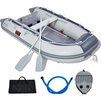
| Provided equipment | Paddles, repair kit, tow line, carrying handle |
| Assembly | Recommended for two adults; sequential inflation of chambers in order: 1 (safety), 2 (floor), 3 (flotation) |
| Cleaning and maintenance | Rinse with fresh water and mild soap after each use; dry completely; store deflated flat, out of reach of rodents |
| Repairs | Small repairs possible with the provided kit (glue and patch); wait 12 hours before reinflating |
| Warranty | 3 years limited (covers manufacturing defects; does not cover normal wear, misuse, or modifications) |
| Safety | Wear a life jacket; do not use under the influence; distribute load evenly; do not leave unattended |
| Warning symbols | Sheltered coastal area up to 300 m; risk of offshore wind and currents; do not use in wind > force 4 or waves > 0.5 m |
| Unfolding temperature | Minimum 15 °C (to avoid damaging the PVC) |
Frequently Asked Questions - LH-18112 Vevor
User questions about LH-18112 Vevor
0 question about this device. Answer the ones you know or ask your own.
Ask a new question about this device
Download the instructions for your Boat in PDF format for free! Find your manual LH-18112 - Vevor and take your electronic device back in hand. On this page are published all the documents necessary for the use of your device. LH-18112 by Vevor.
USER MANUAL LH-18112 Vevor
Technical Support and E-Warranty Certificate www.vevor.com/support
INFLATABLE BOAT
MODEL:LH-18110 / LH-18113 / LH-18112 / LH-18112-1
We continue to be committed to provide you tools with competitive price. "Save Half", "Half Price" or any other similar expressions used by us only represer estimate of savings you might benefit from buying certain tools with us compared to top brands and does not necessarily mean to cover all categories of tools offered by are kindly reminded to verify carefully when you are placing an order with us if yo actually saving half in comparison with the top major brands.
MODEL: LH-18110 / LH-18113 / LH-18112 / LH-18112-1
natural_image
Top-down line drawing of a circular container with internal compartments and small car parts (no text or symbols)NEED HELP? CONTACT US!
Have product questions? Need technical support? Please feel free contact us:
Technical Support and E-Warranty Certificate www.vevor.com/support
This is the original instruction, please read all manual instructions carefully before operating. VEVOR reserves a clear interpretation of user manual. The appearance of the product shall be subject to the product you received. Please forgive us that we won't inform you there are any technology or software updates on our product.
SAFETY WARNINGS
Read the following instructions
Only use this product in the manner described and for its intended purpose. Kee these instructions for use in a safe place. When passing the product on to third parties, please hand over all accompanying documents as well. They contain important details on the product as well as its setup, operation, and maintenance together with safety requirements. Since water sports are always associated with certain amount of risk, detailed knowledge of the product has the potential to prevent personal injury or even death.
Symbols Used
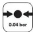
Allowable operating pressure

Labeling on dinghy
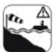
Protected shore zone up to 984 ft (300 m), be cautious of offshore wind and currents!

Do not use at wind speeds exceeding 4 and/or when waves are higher than 19.6 in (0.5 m)!
This product is intended for private use Designed for travel in protected waters near the coast, small bays, on small lakes, narrow rivers, and canals under weather conditions with wind speeds not exceeding 4 as well as with significant waves up to 11.8 in (0.3 m) in height and occasional waves not exceeding 19.6 in (0.5 m) height caused, for example, by ships motoring by.
Safety Information
The dinghy is an inspected and safe water sports vessel. We would still to impress upon you the importance of complying with the following rules and regulations:

Risk of Death!
Never let children play with packaging materials unsupervised. There is a risk of suffocation Never let children play with product unsupervised.

Risk of injury!
Beware of offshore wind!
Beware of offshore currents.
- Keep in mind that persons and loads must be evenly distributed in the boat a all times, since there would other-wise be a risk of capsizing.
- Please observe the information on the identification plate, the allowable load capacity, and number of passengers as well as the warning notices.
● Always comply with the local regulations governing nautical travel.
- Do not transport any sharp or pointy objects The dinghy should be protected against contact with possibly hazardous liquids or acids This could cause irreparable damage.
● Protect the dinghy against heat and fire! Be careful with smoldering cigarettes!
- Make sure the dinghy doesn't end up on stony ground in order to prevent damage to the hull of the vessel. Should one of the three air chambers become damaged during operation on the water, do not under any circumstances leave the dinghy The two intact air chambers should be buoyant enough to keep the dinghy safely above water.
● Never transport the product on a vehicle when it is inflated.
- Never leave your dinghy on the water unattended. It could be washed away faster than you can swim out to get it.
● Always make sure you have the paddle with you before using the vessel otherwise it would be impossible to adequately maneuver it.
- Do not make any technical modifications to the vessel. Changes of any kind pose a risk to the proper operation of the sporting vessel. Never use the product under the influence of alcohol, drugs, or medications.
- Never overestimate your strength and pace yourself while paddling to make sure that you can easily paddle back the way you came at any given time. Stay in protected shore zones up to 984.2 ft(300 m) out and pay attention t changing wind and current conditions that might make movement considerably more difficult.

WARNING!
Maintaining your caution and self-awareness is extremely important on the water. Never overestimate your strength and ability to maneuver! Always stay near the shore! Pay attention to the weather conditions, storm warn
and any light signals!

AWARNING!
Always pay attention to safety requirements and the applicable legal regulations for lakes and open water and always wear an approved life for your own safety.

AWARNING!
Avoid using sunscreen and skin care products containing alcohol.
Sunscreen and skin care products containing alcohol may cause the cold coating to come off of the inflatable PVC material. This may leave color residue on your body clothing, and other objects that come into contact.

AWARNING!
If a person should fall overboard, they must always climb back in over bow or stern, since climbing in on the side would increase the risk of capsizing.
Avoiding Material Damage!
- All inflatable products are susceptible to cold. For this reason, never unfold and inflate the product at a temperature of less than 59^(15^) .
- If the air pressure increases in direct sunlight, it must be offset by releasing an appropriate amount of air.
- Make sure that the product - particularly when inflated - does not come into contact with stones gravel, or sharp objects and does not at any point rub or scrape, because this may cause damage to the surface foil.
- Only plug suitable pump adapters into the safety valve. Otherwise the valves could be damaged.
- Do not over inflate as there is a risk that the welded seams will split. Close it valves fully after inflating.Avoid contact with sharp, hot, pointed, or dangerous objects.
TECHNICAL INFORMATION
| Model | LH-18110 | LH-18113 | LH-18112 | LH-18112-1 |
| Material | PVC | PVC | PVC | PVC |
| Color | Green | Green | Green | Green |
| Load | 500lbs | 750lbs | 1100lbs | 1100lbs |
| Allowable Passengers | 2 | 3 | 5 | 5 |
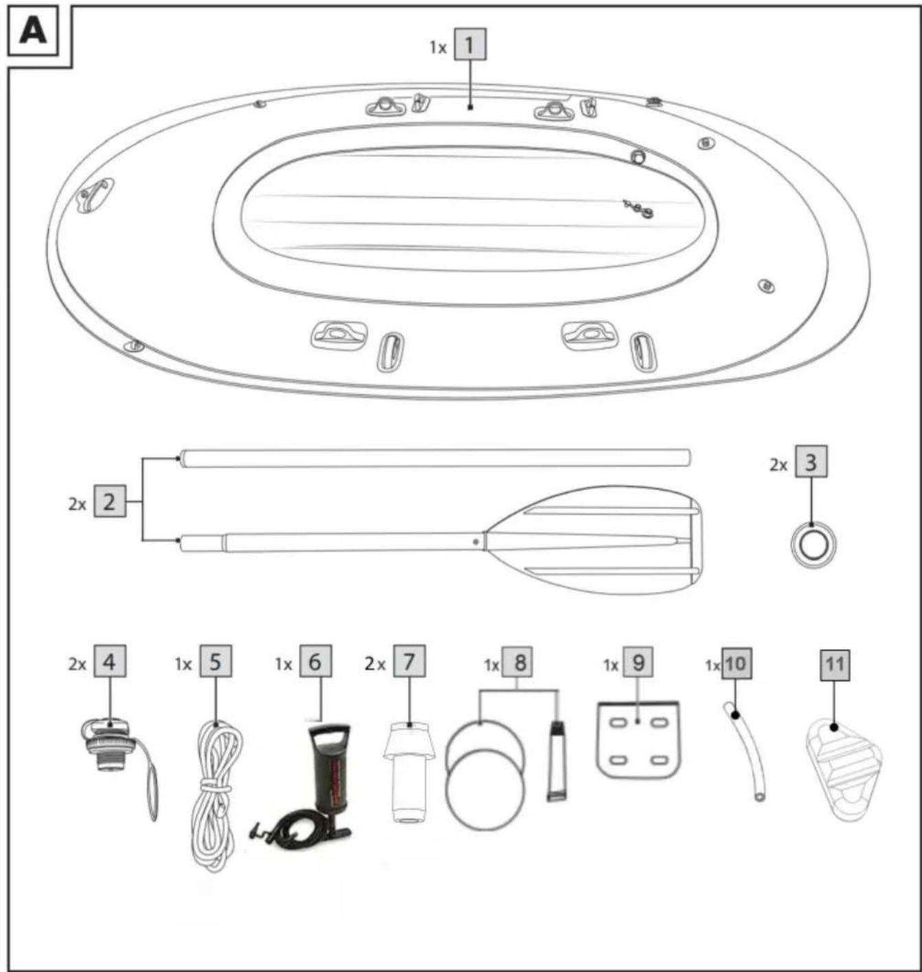
ACCESSORY LIST
| NO | PICTURE | NAME | QTY | NO | PICTURE | NAME | QTY |
| A | 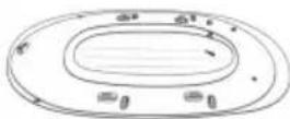 | Inflatable Boat | 1 | F | 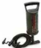 | Pump | 1 |
| B | 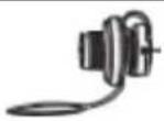 | Screw Valve | 2 | G | 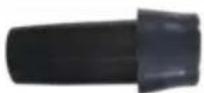 | Fishing Rod Holders | 2 |
| C | 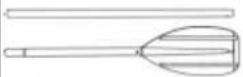 | Paddle/Snap Ring | 2 | H | 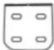 | Gear Pouch | 1 |
| D | 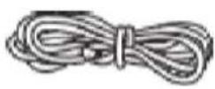 | Cord Set | 1 | I | 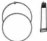 | Repair Kit | 1 |
| E | 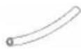 | Vent Line | 1 | J | 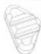 | Inflatable Seats | 0/2/3 |
| Note:The Inflatable seats LH-18110 LH-18113、LH-18112、LH-18112-1 is 、02、2、3. | |||||||
Please follow the individual steps for assembly in the sequence indicated. If the three air chambers are not inflated in the designated order, pressure may be unevenly distributed. This may cause the dinghy to become unstable and could negatively impact the way it maneuvers.
- Due to the size of the product, it should always be assembled by two adults.
- Select a flat and clean surface with enough space to spread out the boat.
Check that all the parts are present and in good condition.
- Starting the second time you set up the vessel, be sure to check it for possible damage, holes and tears and seal them as described in the
- "Repairs" section.Once you are on the water, it may not be possible to repair any damages.
- Do not inflate the air chambers too much in order to avoid overstretching the material. Make sure that the inflated dinghy does not come in contact with stones or other pointy objects and sustain damage.
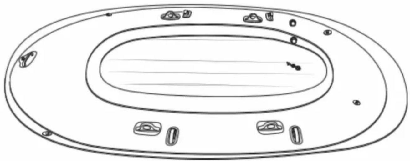
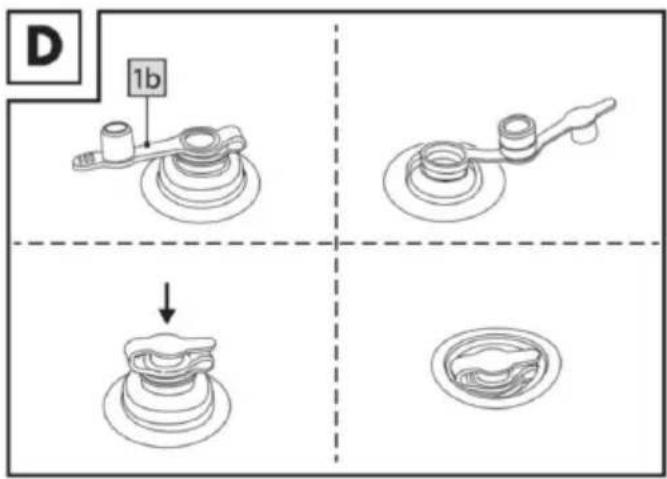
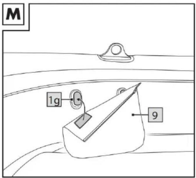
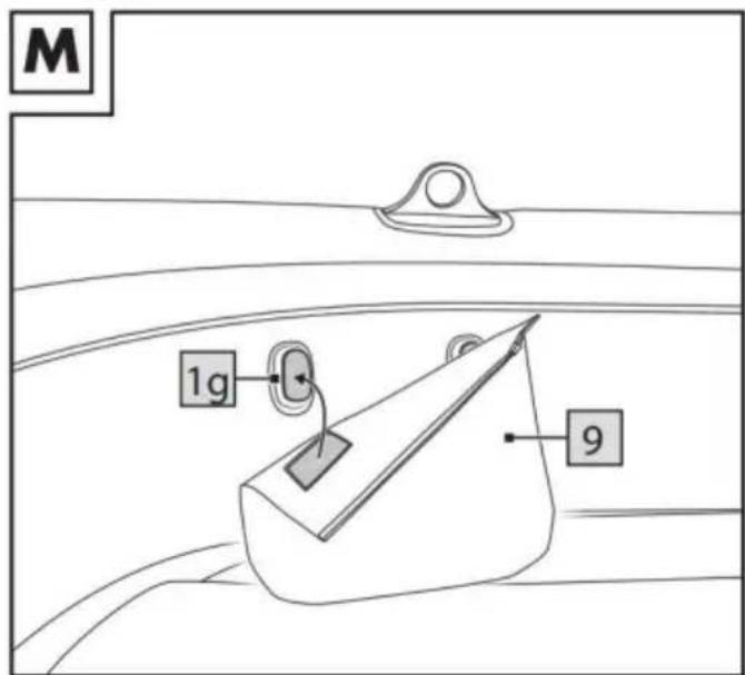
Installing the Screw Valves (Fig.B)
The chambers and of the dinghy are each equipped with a threaded opening for the included screw valves.
- Pull the valve holder loop 4a over the threaded opening 1a so that it rests securely in the groove meant for this purpose.
2.Twist the base ^4b clockwise into the threaded opening.
Inflation

AWARNING!
- Be sure to inflate the air chambers in the correct order.
- The recommended operating pressure is 0.04 bar(= 40 mbar = 0.58 psi). Avoid excessive inflation of the air chambers as there is the risk of overstretching or even tearing the welded seams.
- Use standard foot pumps or double stroke hand pumps with compatible adapters and manometer.
- Do not use a compressor or compressed air bottles to inflate the product. This can damage the product.
● Always inflate all air chambers fully.

Inflation Sequence
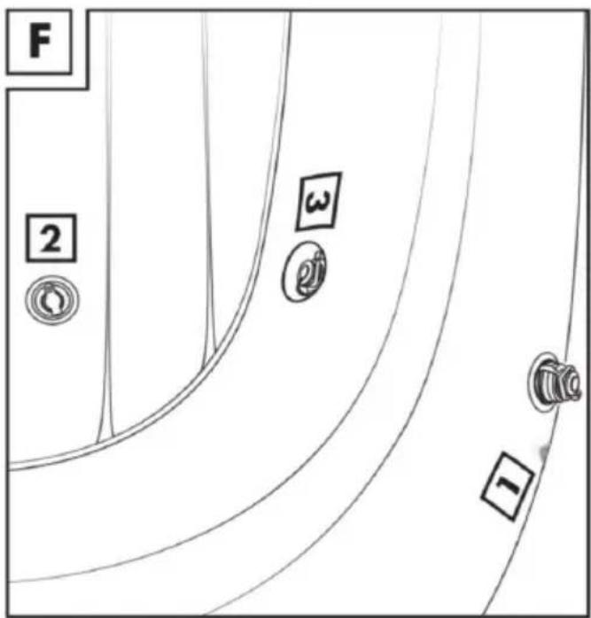
Inflate the air chambers in the following order:
- Safety chamber with screw valve.
- Floor chamber with stopper valve ^2 .
- Flotation chamber with screw valve ^3 .
Note: The air chambers are marked on the dinghy with the corresponding numbers(1)(Fig.F).
Filling the Air Chambers

AIMPORTANT!
The PVC material will stretch out a little when the product is inflated for first time and will never return to its original state. Keep in mind that 1 properties of the product may fluctuate slightly depending on the load it
carrying and outside temperature.
- Use standard foot pumps or double stroke hand pumps with compatible adapters and manometer.
-
Safety chamber with screw valve.
-
Untwist the cap of the screw valve by turning it counterclockwise (Fig. B).
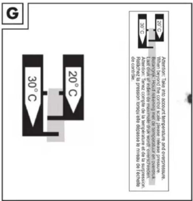
- Inflate the safety chamber until the marked measuring strip matches the temperature on the checking ruler, Attention: Take into account temperature and over pressure When beyond the control scale please release pressure.(Fig.G).
3.Twist on the cap of the screw valve by turning it clockwise.
Note: The safety chamber shouldn't be fully inflated yet.
-
Floor chamber with stopper valve
-
Open the top part of the valve cap (Fig. D).
- Inflate the floor chamber 2 until it feels firm to the touch and there are no longer any creases visible in the material.
Note: When pressing down with your thumb on the air chamber, it should still give slightly.
Note: If a compatible valve adapter is not available, a special valve membrane makes it possible to fill the floor chamber using an adapter in the next size down as well.
- Close the valve cap and press in the valve by applying light pressure (Fig. D).
-
Flotation chamber with screw valve
-
Untwist the cap of the screw valve by turning it counterclockwise (Fig.B).
- Inflate the flotation chamber 3 until the measuring strip on the identification plate is at the same scale as the checking ruler.
- Twist on the cap 4c of the screw valve 4 by turning it clockwise.
Note: The flotation chamber 3 as well as the safety chamber 1 should now be fully inflated. The measuring strip on the safety chamber 1 no longer matches the checking ruler 7. This is correct and it is supposed to be this way.
Accessories
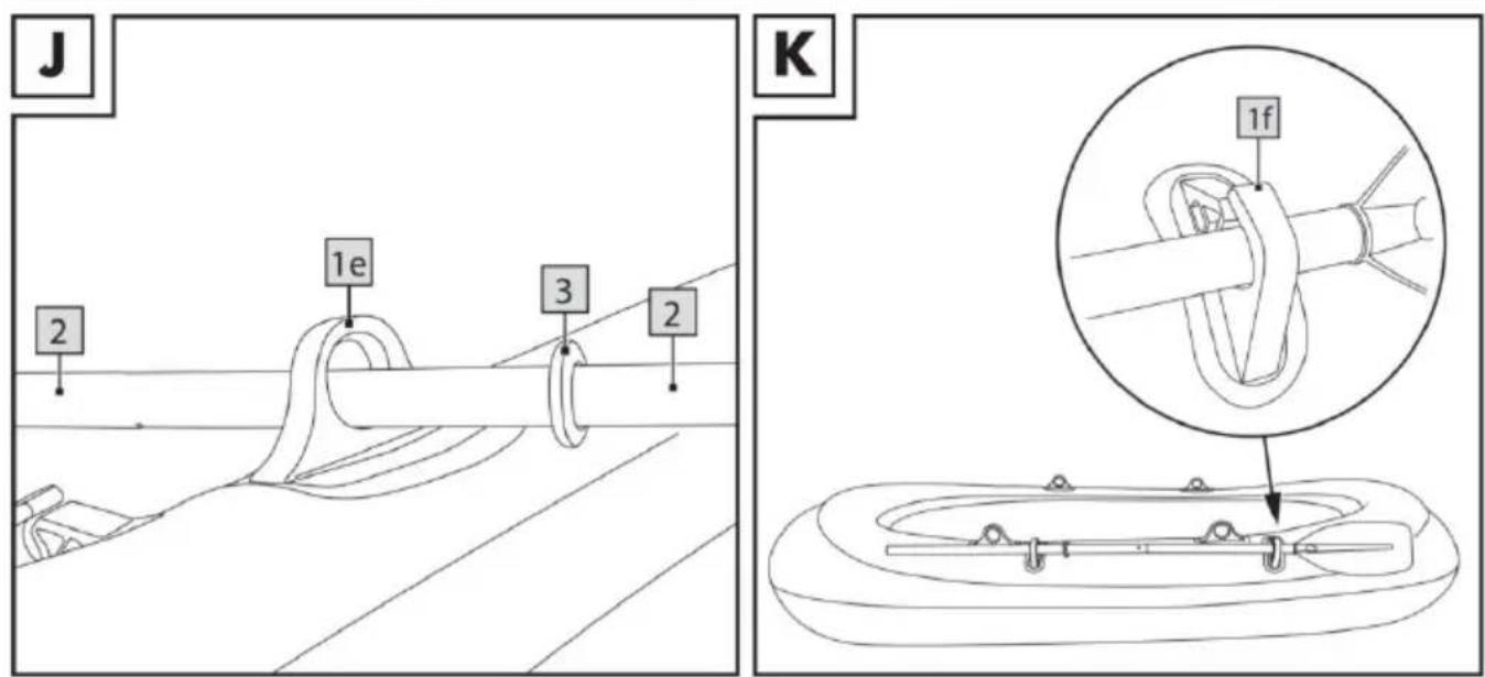
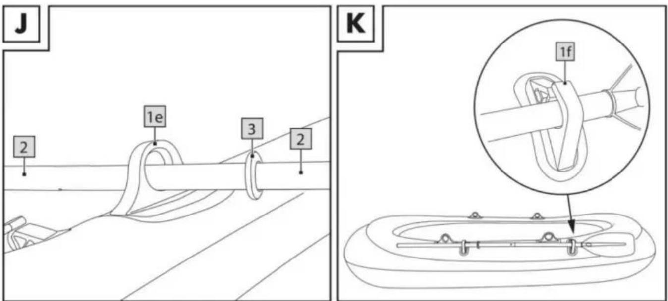
Assembling the Paddle
Note: While the vessel is in use on the water, the paddles should not be removed from the oarlocks, but rather must remain secured in the oarlocks so they are not lost (Fig. H)!
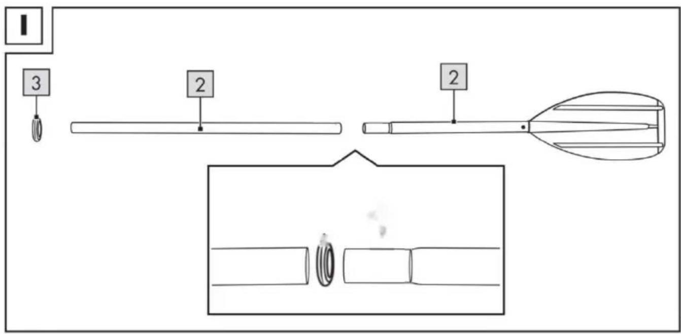
- Connect the two paddle shafts. Twisting the paddle thread. (Fig. I).
- Slide the end of the shaft through the oarlock and secure the paddle by sliding on the drip/snap ring (Fig.J)
- Repeat this process for the second paddle on the other side of the vessel.
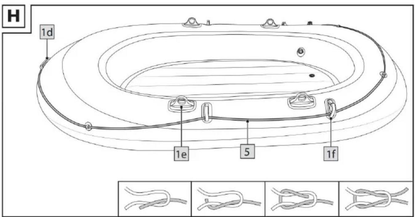
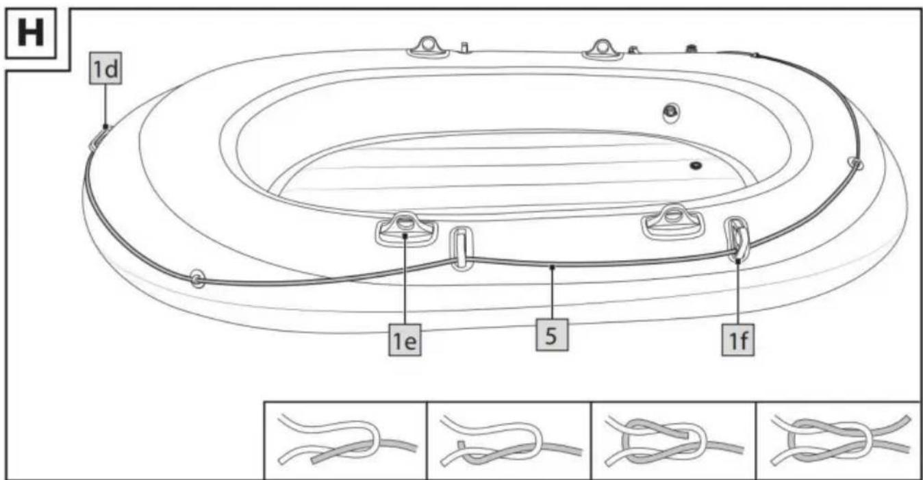
Cord (Fig.H)
Fasten the cords to the eyelets on the vessel.
- Start at the stern and thread the cord 5 through the eyelets meant for this purpose so the cord runs around the dinghy.
- Tie the cord with a square knot.
Dismantling the Dinghy
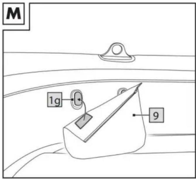
Remove the paddle from the oarlock.
Deflating
Deflate the dinghy as follows:
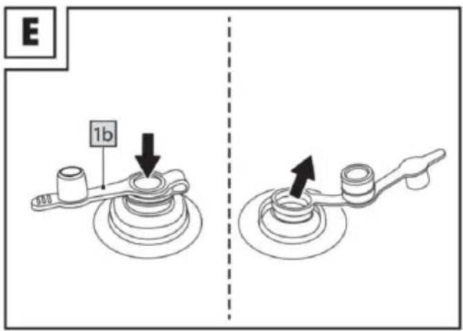
- To deflate the floor chamber, pull out the recessed stopper valve and open the lower part of the valve (Fig. E).
- To deflate air chambers with screw valves,unscrew the screw valves from the
base and allow all of the air to escape (Fig. C).
Disassembling the Paddle
- Twisting the paddle thread.
- Pull the two paddle shafts apart.
Transport
- Two people should always work together to move the dinghy and they should use the cordon the stern as well as the carrying handle on the bow for this purpose (Fig. H).
- Fasten the paddle into the respective paddle holders on the side of the vessel (Fig. K).
Storage, Cleaning
WARNING!
Use only care products that do not contain any acid or gasoline and no use silicone-based products.
Always store the product dry, clean, and deflated at room temperature and ensure that it is out of reach of rodents.
During storage the valves should always be closed. Store the product flat to ensure that it does not become warped.
- Thoroughly clean the dinghy after each use by washing it off with fresh water and mild soap in order to remove any salt crystals, grains of sand, and other ve small particles. Allow it to dry completely afterwards.
- Make sure that all of the air has been pushed out of the air chambers.
- Carefully fold up the dinghy.
Repairs
AWARNING!
Do not under any circumstances attempt to repair major damage yourself. You can repair smaller damage with the supplied repair set.
- Let all of the air out of the dinghy and clean the corresponding spot with an alcohol-based solution. Roughen the area around the tear or hole slightly with a piece of fine sandpaper.
- Cut a patch of the proper size to cover the damaged area and that will overl by0.49 in (1.25 cm) on all sides.
- Apply the repair glue to the affected area on the dinghy as well as the patch the repair glue dry a bit.
- Use a soft object to push the patch onto the affected area.
Note: Be sure to work on a level surface with-out creases or folds. Gently rem possible air bubbles by pushing down with a rounded object from the inside to the outside.
- Wait at least 12 hours after the repairs are finished before inflating the dinghy again.
Disposal
Dispose of the product and the packaging materials in accordance with current local regulations. Packaging materials such as foil bags are not suitable to be given to children. Keep the packaging materials out of the reach of children.

Dispose of the products and the packaging in an environmentally friendly manner.

The recycling code serves to identify various materials for recycling.
The code consists of the recycling symbol-which is meant to reflect the recycling cycle-and a number which identifies the material.
3 year limited warranty
What does this warranty cover?
● The warranty covers: Damage, breakage or inoperability due to defect.
● Damage not caused by normal wear and tear or failure to follow the safety and maintenance instructions provided in the user manual.
What is not covered by the warranty?
● The warranty does not cover damage caused by:
- Normal wear and tear of the product, including fragile parts(such as switches, glass, etc.);
- Improper use or transport;
- Disregarding safety and maintenance instructions; Accidents or acts of nature (e.g. lightning, fire, water, etc.);
- Tampering with the product (such as removing cover, unscrewing screws etc.) Consequential and incidental damages are also not covered under this warranty. However, some states do not allow the exclusion or limitation of incidental or consequential damages, so this limitation or exclusion may not apply to you.
Address : Baoshanqu Shuangchenglu 803long 11hao 1602A-1609shi Shanghai
Imported to AUS: SIHAO PTY LTD. 1 ROKEVA STREETEASTWOOD NSW 2122 Australia
Imported to USA: Sanven Technology Ltd. Suite 250, 9166 Anaheim Place, Rancho Cucamonga, CA 91730
| UK | REP |
Pooledas Group Ltd
Unit 5 Albert Edward House, The Pavilions
Preston, United Kingdom
| EC | REP |
SHUNSHUN GmbH
Römeräcker 9 Z2021, 76351
Technical Support and E-Warranty Certificate
www.vevor.com/support
VEVOR®
TOUGH TOOLS, HALF PRICE
natural_image
Top-down line drawing of a circular container with internal compartments and small objects (no text or symbols)BESOIN D'AIDE? CONTACTEZ-NOUS!


Accessoires
natural_image
Top-down line drawing of a circular container with internal compartments and small objects (no text or symbols)BRAUCHEN SIE HILFE? KONTAKTIERE UNS!
www.vevor.com/support
VEVOR®
TOUGH TOOLS, HALF PRICE
natural_image
Top-down line drawing of a circular container with internal compartments and small objects (no text or symbols)HO BISOGNO DI AIUTO? CONTATTACI!
Importato in AUS: SIHAO PTY LTD. 1 ROKEVA STREETEASTWOOD NSW 2122 Australia
elettronica www.vevor.com/support
VEVOR®
TOUGH TOOLS, HALF PRICE
natural_image
Top-down line drawing of a circular container with internal compartments and small objects (no text or symbols)


Accesorios
natural_image
Top-down line drawing of a circular container with internal compartments and small objects (no text or symbols)POTRZEBUJE POMOCY? SKONTAKTUJ SIĘ Z NAMI!


Akcesoria
Montaż wiosła
www.vevor.com/support
VEVOR®
TOUGH TOOLS, HALF PRICE
Technische ondersteuning en e-garantiecertificaat www.vevor.com/support
OPBLAASBARE BOOT
MODEL:LH-18110 / LH-18113 / LH-18112 / LH-18112-1
natural_image
Top-down line drawing of a circular container with internal compartments and small objects (no text or symbols)HULP NODIG? NEEM CONTACT MET ONS OP!
VEILIGHEIDSWAARSCHUWINGEN

Accessoires
natural_image
Top-down line drawing of a circular container with internal compartments and small objects (no text or symbols)BEHÖVS HJÄLP? KONTAKTA OSS!


Tillbehör
Enhet 5 Albert Edward House, The Pavilions
www.vevor.com/support