
90E - Welding machine Vevor - Free user manual and instructions
Find the device manual for free 90E Vevor in PDF.
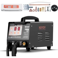


| Product Type | Stud Welder (Car Body Repair Kit) |
| Brand | Vevor |
| Model | 90E |
| Input Voltage | AC 220-240 V, 50 Hz (Standard Model) |
| Output Voltage | AC 1-7 V |
| Input Power | 3 kW |
| Max Instantaneous Output Current | 3500 A |
| Max Input Current | 20 A |
| Working Mode | Automatic / Manual |
| Number of Channels and Modes | 7 channels, 77 preset modes |
| Weld Thickness | 0.6 - 1.2 mm |
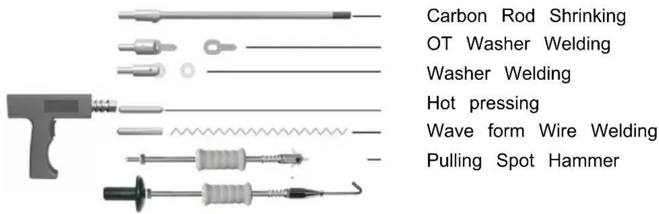
| Main Functions | Spot welding, stud welding, OT joint welding, triangular welding, carbon rod heating, hot pressing, corrugated wire welding |
| Built-in Protection | Overheat protection (automatic shutdown) |
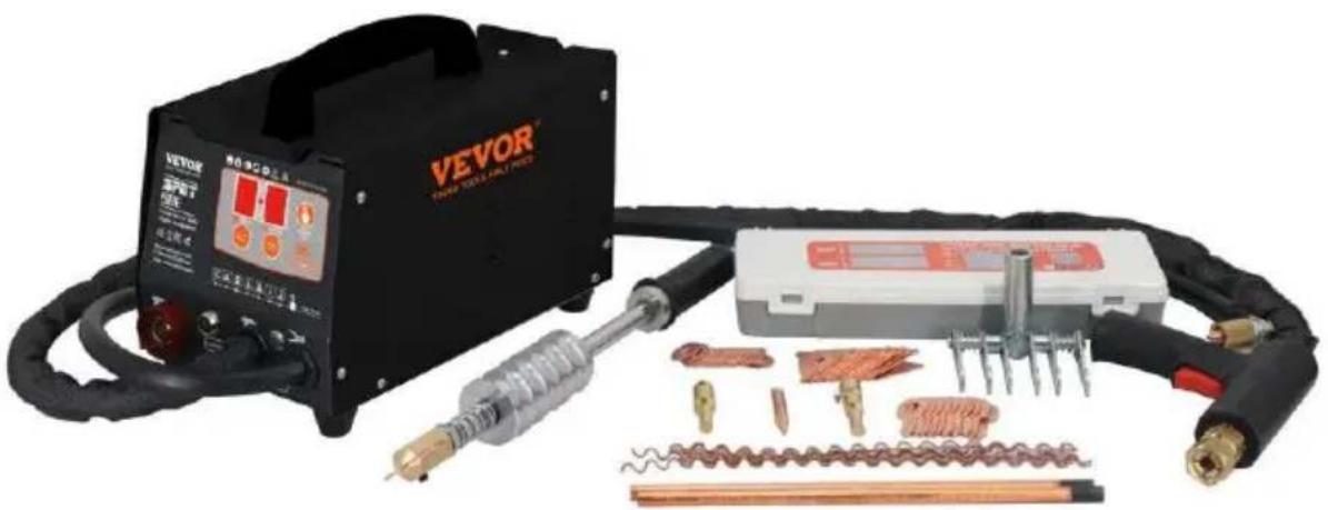
| Included Accessories | Welding gun, pull hammer, 10 corrugated wires, 10 triangular tabs, 10 long spacers (OT), 20 round spacers, 2 carbon rods, suction cup, wrench, hooks, etc. |
| Maintenance and Cleaning | Regularly clean connectors, check cable condition, keep the machine clean and dry |
| Spare Parts and Repairability | Welding accessories (tips, rods, suction cups) are replaceable; contact Vevor after-sales service for parts |
| General Information | Compliant with CE and UKCA standards; meets FCC Part 15 rules (Class B) |
Frequently Asked Questions - 90E Vevor
User questions about 90E Vevor
0 question about this device. Answer the ones you know or ask your own.
Ask a new question about this device
Download the instructions for your Welding machine in PDF format for free! Find your manual 90E - Vevor and take your electronic device back in hand. On this page are published all the documents necessary for the use of your device. 90E by Vevor.
USER MANUAL 90E Vevor
Technical Support and E-Warranty Certificate www.vevor.com/support
STUD WELDER DENT REPAIR KIT
MODEL: 90E
We continue to be committed to providing you with tools at competitive prices. "Save Half", "Half Price", or any other similar expressions used by us represent an estimate of savings you might benefit from buying certain tools from us compared to the major top brands, and do not necessarily mean to cover all categories of tools offered by us. You are kindly reminded to verify carefully when placing an order with us if you are actually saving half in comparison to the top major brands.
MODEL: 90E
NEED HELP? CONTACT US!
Have product questions? Need technical support? Please feel free to contact us:
Technical Support and E-Warranty Certificate www.vevor.com/support
This is the original instruction. Please read all manual instructions carefully before operating. VEVOR reserves a clear interpretation of the user manual. The appearance of the product shall be subject to the product you received. Please forgive us that we won't inform you of any technology or software updates on our product.
| FC | Warning-To reduce the risk of injury, user must read instru manual carefully. |
| FCC Information:CAUTION: Changes or modifications not expressly approved the party responsible for compliance could void the user's authority to operate the equipment!This device complies with Part 15 of the FCC Rules. Ope subject to the following two conditions:1) This product may cause harmful interference.2)This product must accept any interference received, includ interference that may cause undesired operation.WARNING: Changes or modifications to this product not expressly approved by the party. responsible for compliance void the user's authority to operate the product.Note: This product has been tested and found to comply limits for a Class B digital device pursuant to Part 15 of Rules, These limits are designed to provide reasonable pro against harmful interference in a residential installation.This product generates, uses and can radiate radio freer energy, and if not installed and used in accordance with instructions, may cause harmful interference to radio communications. However, there is no guarantee that interfere will not occur in a particular installation. If this product do harmful interference to radio or television reception, which determined by turning the product off and on, the user is encouraged to try to correct the interference by one or m following measures.Reorient or relocate the receiving antenna.Increase the distance between the product and receiverConnect the product to an outlet on a circuit different fi which the receiver is connected.Consult the dealer or an experienced radio/TV technician assistance. | |
| CORRECT DISPOSAL This product is subject to the provision of European Direct 2012/19/EC. The symbol showing a wheelie bin crossed th indicates that the product requires separate refuse collection the European Union. This applies to the product and all accessories marked with this symbol. Products marked as may not be discarded with normal domestic waste, but mut taken to a collection point for recycling electrical and elect devices | |
| CE | Compliance is a EC & UK security certification. |
IMPORTANT SAFEGUARDS
| ! | Operate this protection with working conditions common sense installing and operating the welder, look at the following safety precautions |
| Read the instructions 1. before the operation of the machine, read the product brochures in detail. 2.Please use the original and accessories. | |
| To prevent electric shock: 1. Do not use the skin and wet cl contact welding machine. 2. Do not turn off the power supply, not let the cable around the operator who wear a thick bottom insulation shoes 3. Ground and work directly connected. | |
| When using the machine, wear a mask to avoid problems with exploding will cause harm. | |
| In the workplace, due to welding will produce toxic gases, pay to ventilation, so as not to poison. (Prohibited in the closed c welding) | |
| Static electricity can damage the machine's circuit board 1. connected to a good ground, to prevent electricity. 2. in the movement and storage to use anti-static items cover to avoid damage to the machine. | |
| 1. splash of sparks and arc will cause damage to eyes 2. please wear a mask or with the edge of the glasses | |
| Do not touch the hot workpieces by hand during welding. | |
| To prevent the explosion: flammable, explosive products away the welding area. | |
| 1. The electromagnetic field can affect the operator's heart, es if they have a pacemaker installed. Please keep away from the machine. 2. If you need assistance operating the machine, feel free to advice for life. | |
| Be careful not to be crushed and bruised while moving. | |
| Please avoid prolonged operation, as it may cause overheating machine's components and reduce its lifespan. | |
| Prohibit welding at high. | |
| After completing welding, check the welded area for overheating spatter and hot metal to prevent fires. | |
Note: Welder self-protection! Focus on others' safety! Focus on plant safety! Pay attention to equipment maintenance!
General safety rules:
Before removing the body of the product, pull out the wire first.
The operator must be qualified accordingly.
The operation can only be controlled by qualified technicians.
Operators are responsible for complying with automotive manufacturers' protective procedures for electrical and electronic systems (on-board computers, on-board radios, alarms, airbags, etc.).
The compressed air supply must be shut off and the machine turned off before maintenance operations are carried out.
Electrodes, electrode arms, and other secondary conductors can reach very high temperatures and remain hot for a long time after the machine is stopped. Beware of scalding.
Preventive maintenance is necessary on a regular basis.
Power Connection:
- Check that the device is properly connected to the ground coupler and that the ground connection is in good condition.
- Check if the workbench is connected to the ground connector. Ensure that the operator does not have any contact with the metal to be welded, and that they are not wearing protective or wet clothing.
- Avoid contact with welded parts.
- Do not spot weld in very wet places or on wet floors.
- Do not weld with worn cables. Check that the insulation does not have defects and that connections are not loose.
- Turn off the device before replacing the electrode.
- Disconnect the equipment before it is controlled or repaired.
Protection of Eyes and Body:
- During welding, wear leather gloves, a welding apron, safety shoes, welding protective clothing, and arc-filtering and radiation-protective helmets or glasses. The operator must protect their eyes during grinding and hammering.
- Do not wear rings, watches, or jewelry. They can cause burns.
- All protective boards must be in good condition and in proper position. In the absence of eye protection, do not look at the welding arc. Protect the environment near the product from projection and reflection.
Welding Fume:
Welding operations can lead to the emission of toxic smoke and harmful metals. The equipment should be installed in covered areas with smoke extractors. Operators must wear smoke masks. Welding materials must be cleaned.
Pay Attention to Fire:
- Check whether sparks cause fires, especially in the vicinity of flammable materials.
- Check that the fire extinguisher is not far from the operator.
- Place the equipment where there are pneumatic devices.
- Do not weld on a container with flammable and lubricant, even if it is empty.
- Do not weld in an atmosphere filled with flammable gas or fuel vapor.
Electromagnetic Compatibility:
Near the welding site, check:
- There are no other power cords, control cables, telephone lines, radio or television reception equipment, watches, mobile phones, magnetic cards, computers or any other electronic device.
- No active medical devices (pacemakers, acoustic prostheses) were used around (at least 3 meters).
FCC INFORMATION
CAUTION:
Changes or modifications not expressly approved by the party responsible for compliance could void the user's authority to operate the equipment!
This device complies with Part 15 of the FCC Rules. Operation is subject to the following two conditions:
1) This product may cause harmful interference. 2) This product must accept any interference received, including interference that may cause undesired operation.
WARNING:
Changes or modifications to this product not expressly approved by the party responsible for compliance could void the user's authority to operate the product.
Note:
This product has been tested and found to comply with the limits for a Class B digital device pursuant to Part 15 of the FCC Rules. These limits are designed to provide reasonable protection against harmful interference in a residential installation.
This product generates, uses and can radiate radio frequency energy, and if not installed and used in accordance with the instructions, may cause harmful interference to radio communications. However, there is no guarantee that interference will not occur in a particular installation. If this product does cause harmful interference to radio or television reception, which can be determined by turning the product off and on, the user is encouraged to try to correct the interference by one or more of the following measures.
- Reorient or relocate the receiving antenna.
- Increase the distance between the product and receiver.
- Connect the product to an outlet on a circuit different from that to which the receiver is connected.
- Consult the dealer or an experienced radio/TV technician for assistance.
Installation
- Specifications and parameters
| Model | 90E | 90E |
| Input voltage (V) | AC220-240V 50Hz | AC120V 60Hz |
| Output voltage (V) | AC1-7V | AC1-7V |
| Input power (KW) | 3KW | 3KW |
| Instantaneous maximum output current (A) | 3500A | 3500A |
| Input the maximum current (A) | 20A | 20A |
| Way of working | Automatic/manually | Automatic/manually |
| Regular working hours | Automatic mode program setting | Automatic mode program setting |
| Work stalls | 7 channels 77 modes | 7 channels 77 modes |
| Welding thickness (mm) | 0.6-1.2 | 0.6-1.2 |
| Aisle | coding | Name | Stalls | Power Consumption (kw) |
| 1 | Triangle sheet welding | 1-5 file preferred | 0.8-2.0 | |
| 2 | Gasket welding | 2-5 file preferred | 0.8-2.5 | |
| 3 | OT gasket welding | 3-5 file preferred | 0.8-2.3 | |
| 4 | Wave line spot welding | 4-5 file preferred | 0.8-2.5 | |
| 5 | Hot pressing | 5-5 file preferred | 0.8-2.8 | |
| 6 | Carbon rod heating | 6-3 file preferred | 0.8-2.0 | |
| 7 | Stud welding | 7-5 file preferred | 0.8-3.0 |
2. The work cycle and overheating protection
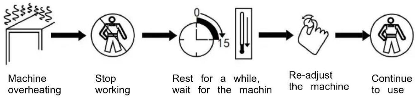
The working cycle of the machine is a repeated cycle of work, with cycle time consisting of load time and no-load time.
In addition, the machine is equipped with overheating protection. When the temperature reaches a critical level, the welding machine will automatically stop working. After it cools down, you can continue operating, depending on the specific situation.
3. Installation of the machine
1) When customers receive the machine, first open the package and find the product brochure.
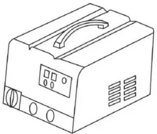
2) According to the instructions in the packing list, check the items and verify that the machine accessories and quantities are correct. 3) According to the machine's appearance picture, install the machine and check for any other problems. If there are any questions, please consult the dealer or service solution.
4. Moving and placing the machine: precautions
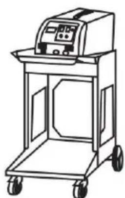
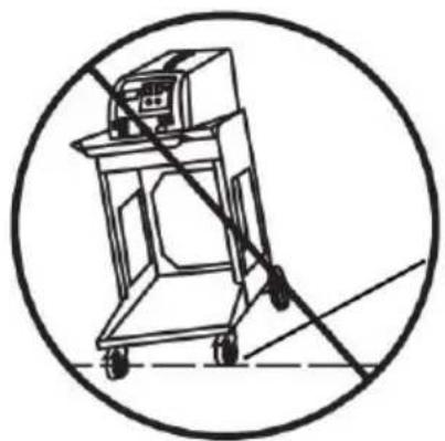
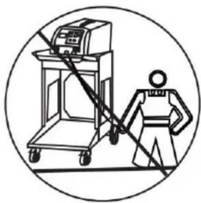
1) After installation, if there are no other problems, choose a suitable place to put the machine. 2) The length of the input power cord is determined according to the operating distance, and the power cord must be at least 4 mm² copper cable. 3) When placing the machine, it must not be tilted; it should be stable on the ground to avoid damage. 4) When moving the machine, use a pulley or lift it with the machine's lifting points. Do not drag the machine or pull the cable to move it. Otherwise, it may damage the machine or break the cable, causing inconvenience for later work.
As shown:
- Power supply connection method
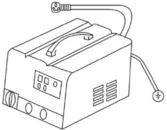
Insert the plug into an appropriate socket according to the plug supplied with the unit. Be sure to check the voltage.
Operating
- Operation panel guidelines

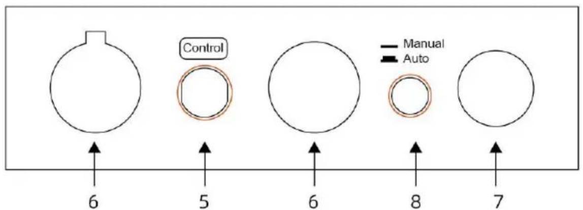
1. Welding mode 2. Mode confirmation 3. Adjust 4. Power mode 5. Control 6. Ground line 7. Torch line 8. Manual/automatic switching
Note:
Machine overload work will enter the protection state, until the machine cools down and then work.
2. Welding torch and connector
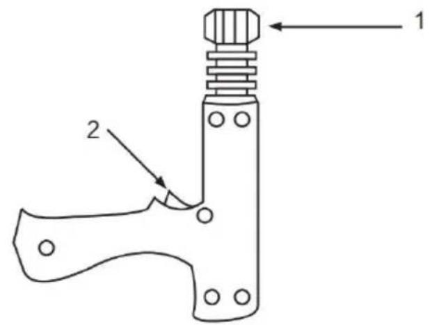
- Locking head
- Torch switch
Application of single-sided spot welding gun
Connection of negative wire
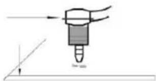
- Place the wire on the sheet metal section that needs to be repaired, as close to the welding area as possible.
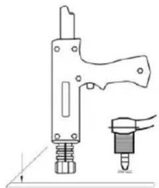
- the welding torch in the vicinity of the machine near the automatic welding
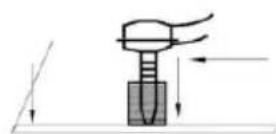
- Fixed ground
For the negative connection, the code can be selected as 1 and the power can be selected as 6. The power can be increased, granting a higher number of welds to dissolve the plating on the negative tip.
3. Method of operation
a. Gasket welding
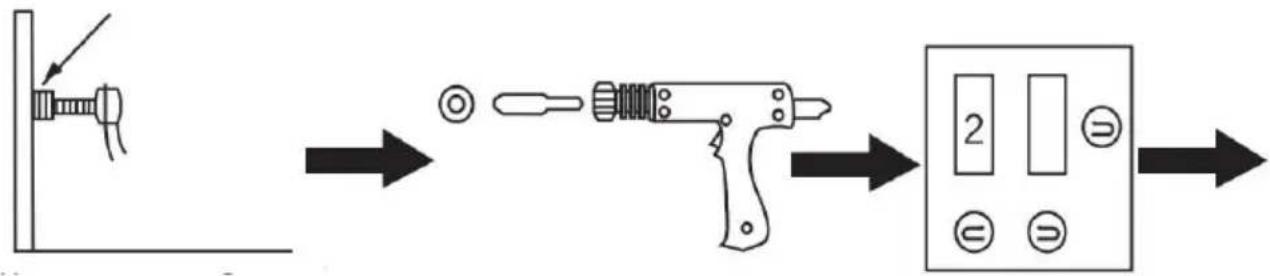
The negative line fixed 1 the polished clean and remove the paint on the workpiece, the closer the operating surface the better.
Connect the gasket connector to the torch and lock it with a gasket.
Select the appropriate welding mode.
Adjust the appropriate power.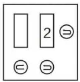
Lightly press the welding torch against the body at the depressed areas, and the machine will weld automatically.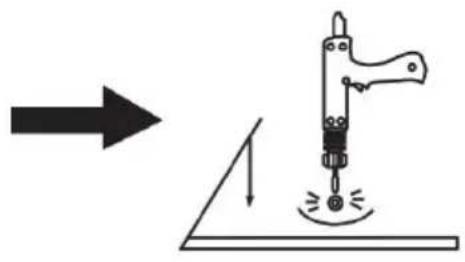
Remove the welding torch, and use a strong pull hammer to pull the gasket in the opposite direction to pull out the depression.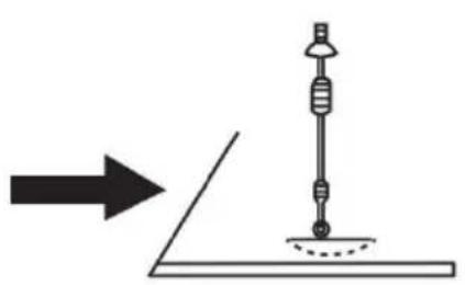
OT gasket welding is the same as gasket welding: code 3, power priority 5, other steps as gasket welding.
Note:
- Before doing this, test on other workpieces to avoid damaging the vehicle's surface due to excessive current or too long a duration.
- According to the body plate thickness, select the appropriate gear; the machine will automatically match the welding time with the current.
- After doing this, you can continue with other functional operations. If you do not continue working, turn off the power and cut off the main switch, and finish cleaning the various accessories for the next use. b. Triangular pieces welding
Fix the negative line to a polished clean area and remove the paint on the workpiece; the closer to the operating surface, the better. Connect the triangular pull hammer to the torch and lock it. Select the appropriate welding mode.
Adjust the appropriate power. Lightly press the welding torch against the body at the depressed areas, and the machine will weld automatically. Pull the recessed parts directly in the opposite direction of the hammer welding.
Note:
- Before doing this operation, please try on other parts to avoid the current being too large or the duration too long, which could damage the body surface to be repaired.
- According to the body plate thickness, select the appropriate gear; the machine will automatically match the welding time with the current.
- For triangular pieces welding, before replacing the meson repair, the depression should be pulled out directly after welding.
- After doing this operation, you can continue with other functional operations. If you do not continue working, please turn off the power and cut off the main switch, and finish cleaning the various accessories for the next use.
c. Carbon rod heating
The negative line fixed to the polished clean and remove the paint on the workpiece, the closer the operating surface is better. Connect the connected triangular pull hammer to the torch and lock it. Select the appropriate welding mode.
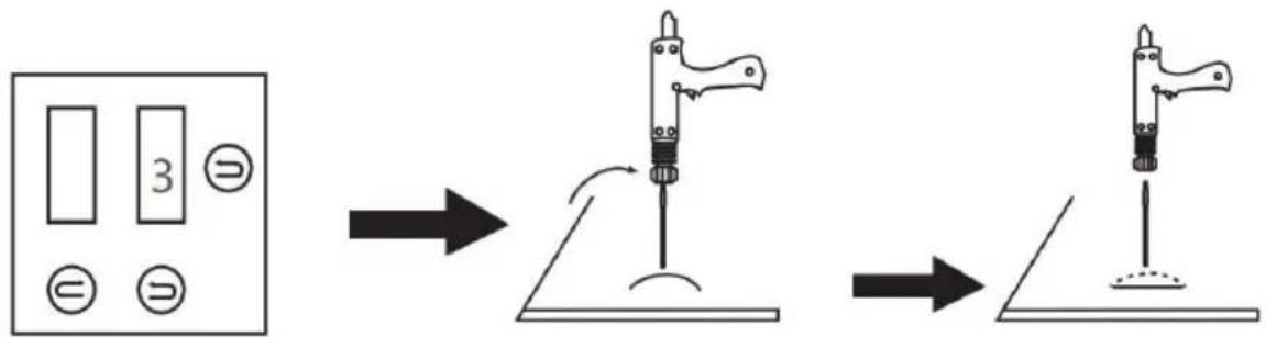
Adjust the appropriate power.
The carcass is heated in clockwise direction.
With cold water or wet cloth place just to the location of the use of thermal expansion and contraction the prominent part of the tightening to return to normal.
Note:
- before doing this operation, please try the other parts in order to avoid the current is too large or too long to damage the body to repair the surface.
- according to the body plate thickness, select the appropriate gear, the ma will automatically match the welding time with the current.
- after doing this operation, you can continue to other functional operation, if do not continue to work, please turn off the power and cut off the main sw various accessories finishing for the next use.
d.wave line welding
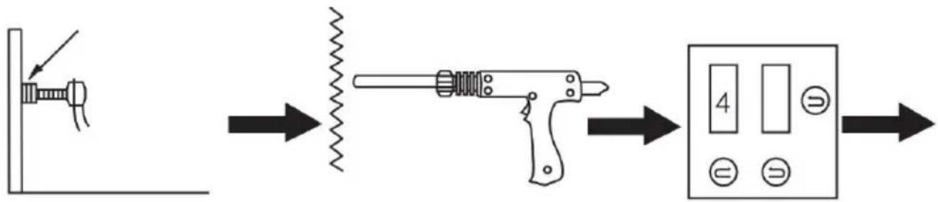
The negative line fixed to the polished clean and remove the paint on the workpiece, the closer the operating surface t better .
Connect the connected triangular pull hammer to the torch and lock it.
Select the appropriate welding mode.
Adjust the appropriate power. Place the waveform line upright in the car body and place the welding head on the upright waveform line. The machine will automatically weld. With a claw pull hook a hammer set in the waveform line, the car body depression out.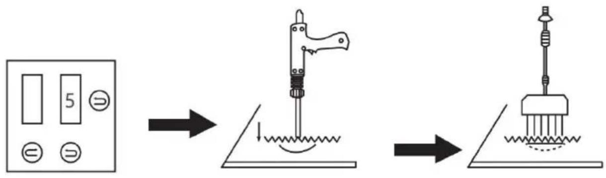
Note:
- Before doing this operation, please first test on the other parts, so as to the current is too large or too long damage to repair Body surface.
- According to the body plate thickness, select the appropriate gear, and the machine will automatically match the welding time with the current.
- After performing this operation, you can continue with other functions. If you do not need to continue working, turn off the power and cut off the main switch. Then, organize the various accessories for the next use.
e. Use of the suction cup
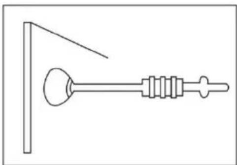
Using the manual suction cup:
- Connect the suction cup to the pull hammer.
- Force the suction cup onto the depression without any dead angles.
- Pull the hammer in the opposite direction.
Maintenance and repair
Failure and troubleshooting
| Trouble | Reason | Remedy |
| No welding output | 1. Connected power supply incorrectly. 2. Power switch in off position | 1. Connect power supply according to manufacturer's instructions. 2. Place power switch in position. |
| Trigger not working | 1. Trigger damaged. 2. Gun control wire broken. 3. Control wire plug loosen. 4. Mode switch in incorrect position. | 1. Replace trigger. 2. Connect again or replace if necessary. 3. Connect control wire plug again. 4. Place Mode switch in correct position. |
| Poor weld | 1. Amperage too low 2. Input power cord did no meet the requirement. 3. Ground clamp bad conta | 1. Increase amperage setting 2. Replace input power coil 3. Change ground clamp location. |
| Piercing workpiece | 1. Output amperage too high 2. Bad contact of electrode tip or washer with workpiece | 1. Reduce amperage setting 2. Remove coating from material reduce added pressure. |
| Carbon rod working unstable | 1.Carbon rod or workpiece dirty. 2.Incorrect amperage and time setting. | 1. Polish carbon rod and workpieces 2. Set amperage and time according to workpiece thickness |
| Unit stop working while operation | 1.Trigger plug loosen. 2.Gun control wire broken. 3.Over heating. | 1. Check gun control wire and trigger plug. 2. Wait for temperature codown |
Packing list
| Part name | Quantity | Remarks |
| Mainframe | 1 | |
| Tool Box | 1 | |
| Pulling Hammer | 1 | |
| Pulling gun | 1 | |
| Wavy wire | 10 | wwwww |
| meson head | 1 | |
| Carbon Rod Head | 1 | |
| Spot Welding Head | 1 | |
| Carbon Rods | 2 | |
| Wrench | 1 | |
| Pull Hook | 1 | |
| Six-jawed Hook | 1 | |
| Triangle Tabs | 10 | |
| Long shims (OT) | 10 | |
| Round Spacer | 20 | |
| Suction Cups | 1 |
VEVOR
TOUGH TOOLS, HALF PRICE
Technical support and e-warranty certificate
www.vevor.com/support
VEVOR®
TOUGH TOOLS, HALF PRICE
Technical support and electronic warranty certificate www.vevor.com/support
DENT PULLER KIT FOR STUD WELDER
MODEL: 90E
www.vevor.com/support
VEVOR®
TOUGH TOOLS, HALF PRICE
Technical support and electronic warranty certificate www.vevor.com/support
VEVOR®
TOUGH TOOLS, HALF PRICE
Technical support and electronic warranty certificate www.vevor.com/support
www.vevor.com/support
VEVOR®
TOUGH TOOLS, HALF PRICE
www.vevor.com/support
VEVOR®
TOUGH TOOLS, HALF PRICE
www.vevor.com/support
- STUD WELDER DENT REPAIR KIT
- MODEL: 90E
- NEED HELP? CONTACT US
- IMPORTANT SAFEGUARDS
- GENERAL SAFETY RULES
- POWER CONNECTION
- PROTECTION OF EYES AND BODY
- WELDING FUME
- PAY ATTENTION TO FIRE
- ELECTROMAGNETIC COMPATIBILITY
- FCC INFORMATION
- CAUTION
- WARNING
- NOTE
- INSTALLATION
- THE WORK CYCLE AND OVERHEATING PROTECTION
- INSTALLATION OF THE MACHINE
- MOVING AND PLACING THE MACHINE: PRECAUTIONS
- AS SHOWN
- OPERATING
- WELDING TORCH AND CONNECTOR
- CONNECTION OF NEGATIVE WIRE
- METHOD OF OPERATION
- USE OF THE SUCTION CUP
- MAINTENANCE AND REPAIR
- VEVOR
- VEVOR®
- TOUGH TOOLS, HALF PRICE
- DENT PULLER KIT FOR STUD WELDER
Brand : Vevor
Model : 90E
Category : Welding machine