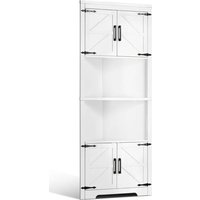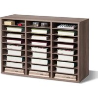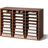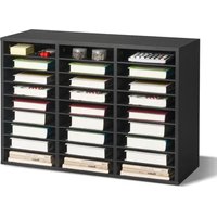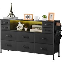
ZWE-BC-SS-08 - Wardrobe Vevor - Free user manual and instructions
Find the device manual for free ZWE-BC-SS-08 Vevor in PDF.


User questions about ZWE-BC-SS-08 Vevor
0 question about this device. Answer the ones you know or ask your own.
Ask a new question about this device
Download the instructions for your Wardrobe in PDF format for free! Find your manual ZWE-BC-SS-08 - Vevor and take your electronic device back in hand. On this page are published all the documents necessary for the use of your device. ZWE-BC-SS-08 by Vevor.
USER MANUAL ZWE-BC-SS-08 Vevor
Technical Support and E-Warranty Certificate www.vevor.com/support
FABRIC DRAWER DRESSER USER MANUAL
MODEL: ZWE-BC-SS-07 / ZWE-BC-SS-08 ZWE-BC-SS-09/ ZWE-BC-SS-10
We continue to be committed to provide you tools with competitive price. "Save Half", "Half Price" or any other similar expressions used by us only represents an estimate of savings you might benefit from buying certain tools with us compared to the major top brands and does not necessarily mean to cover all categories of tools offered by us. You are kindly reminded to verify carefully when you are placing an order with us if you are actually Saving
Half in comparison with the top major brands
VEVOR®
TOUGH TOOLS, HALF PRICE
FABRIC DRAWER DRESSER
MODEL: ZWE-BC-SS-07/ ZWE-BC-SS-08
ZWE-BC-SS-09/ ZWE-BC-SS-10
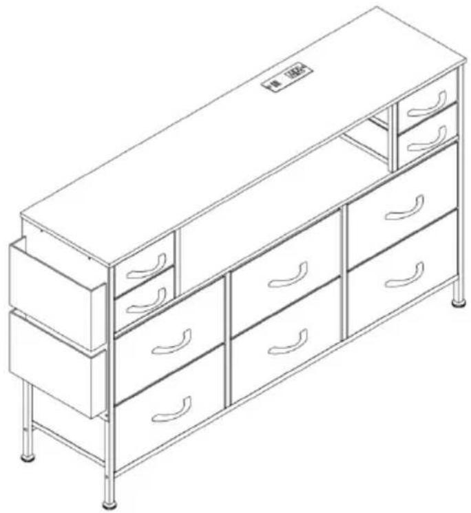
natural_image
Line drawing of a multi-level office cabinet with drawers and metal supports (no text or symbols)NEED HELP? CONTACT US!
Have product questions? Need technical support? Please feel free to contact us:
Technical Support and E-Warranty Certificate www.vevor.com/support
This is the original instruction, please read all manual instructions carefully before operating. VEVOR reserves a clear interpretation of our user manual. The appearance of the product shall be subject to the product you received. Please forgive us that we won't inform you again if there are any technology or software updates on our product.
SAFETY INSTRUCTIONS
WARNING:
Read this material before using this product. Failure to do so can result in serious injury.
Assembly precautions
- Assemble only according to these instructions. Improper assembly can create hazards.
- Wear ANSI-approved safety goggles and heavy-duty work gloves during assembly.
- Keep the assembly area clean and well-lit.
- Keep bystanders out of the area during assembly.
- Do not assemble if tired or when under the influence of alcohol, drugs or medication.
- The product capabilities apply to properly and completely assembled products only.
- Assemble on a flat, level, hard and smooth surface capable of safely supporting the Fabric Drawer Dresser.
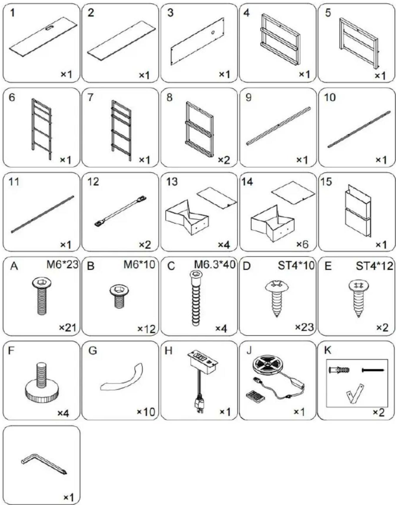
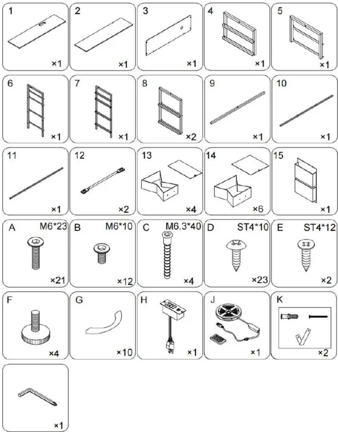
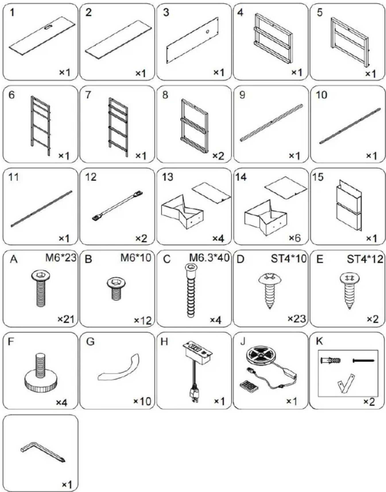
- For additional information regarding the parts listed in the following pages, please refer to the Assembly Diagram of this manual. Unwrap and separate all parts in a clean work area.
Use precautions
- DO NOT SIT OR STAND ON THIS ITEM.
- This product is not a toy. Do not allow children to play with or near this item.
- Do not exceed specified weight capacities.
- Use only on a flat, level, hard, and smooth surface that can safely support a fully loaded Fabric Drawer Dresser.
- Use as intended only.
- Inspect before every use; do not use if parts are loose or damaged.
SAVE THIS MANUAL
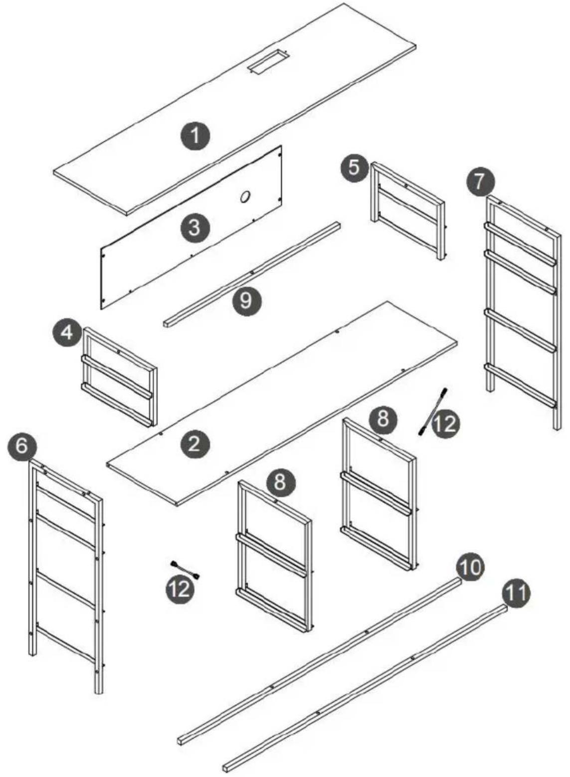
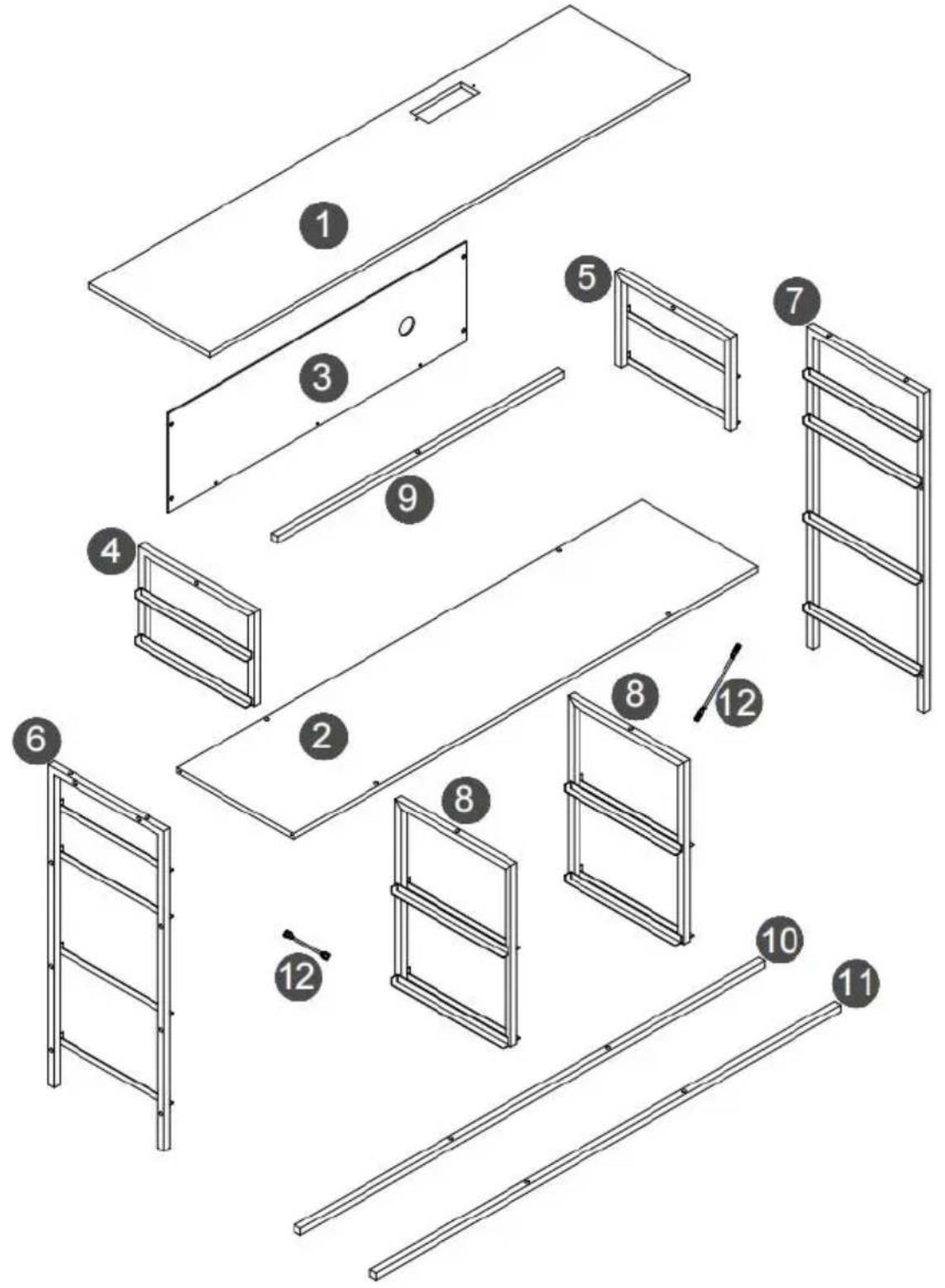
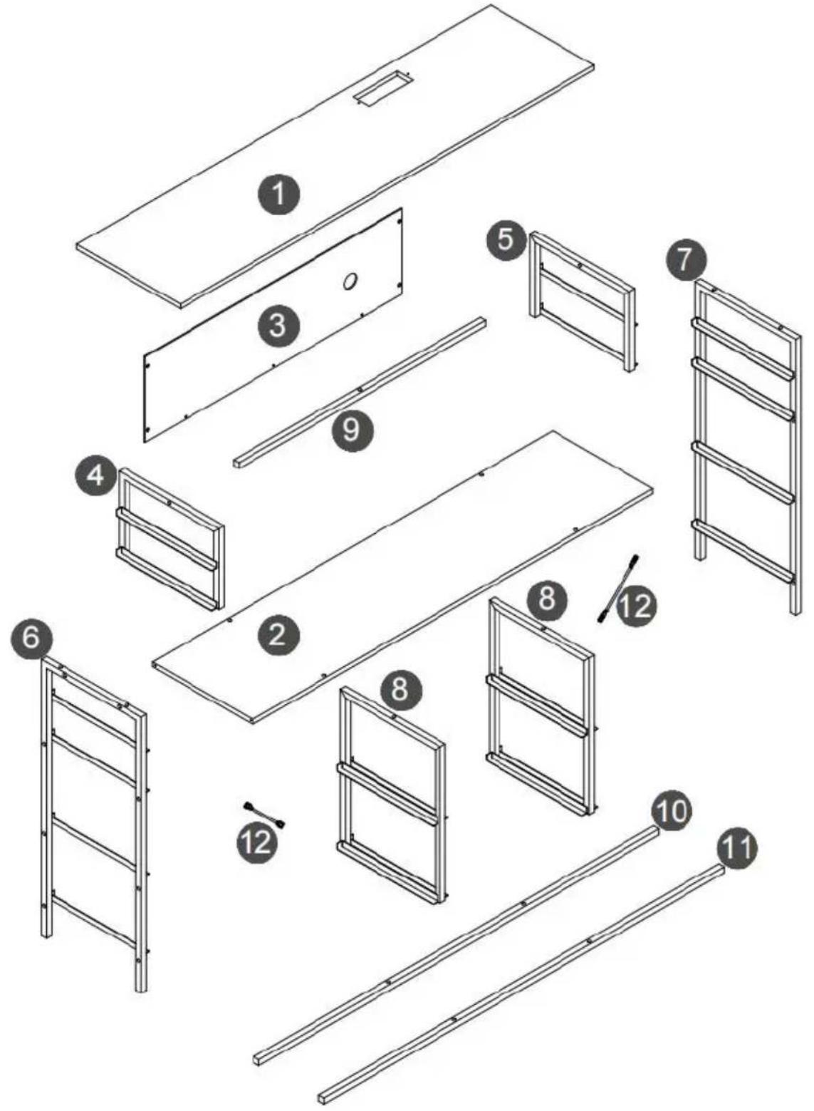
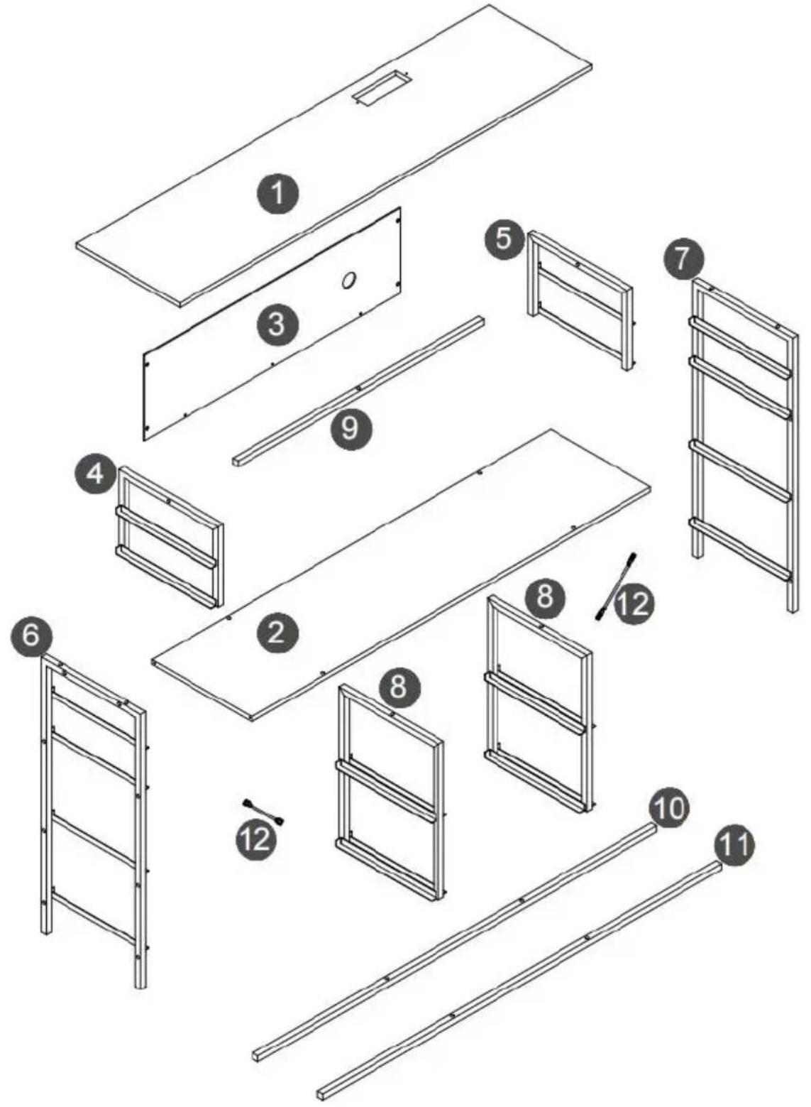
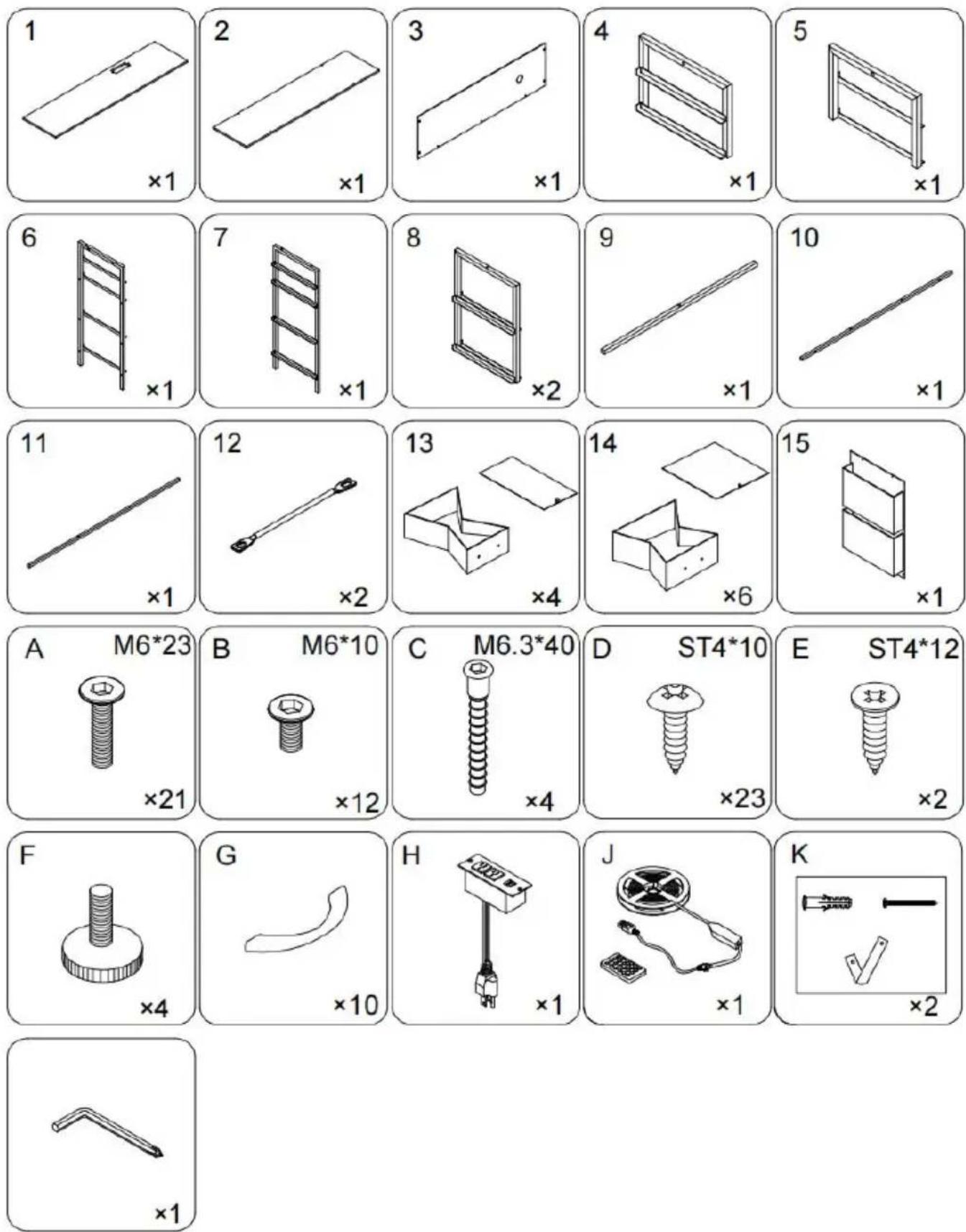
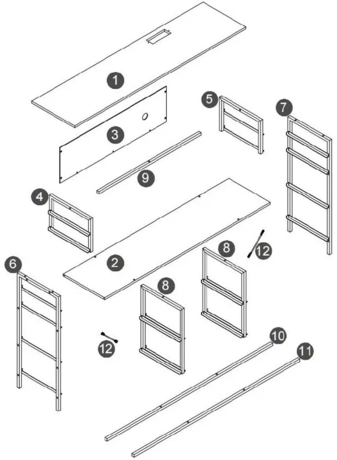
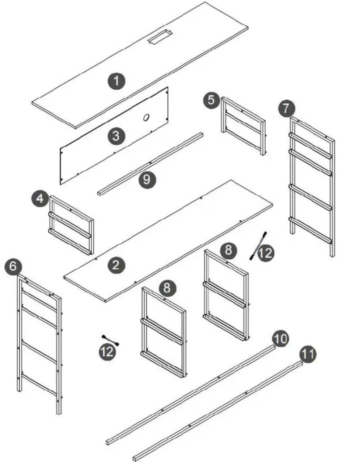
EXPLODED DRAWING

WARNING
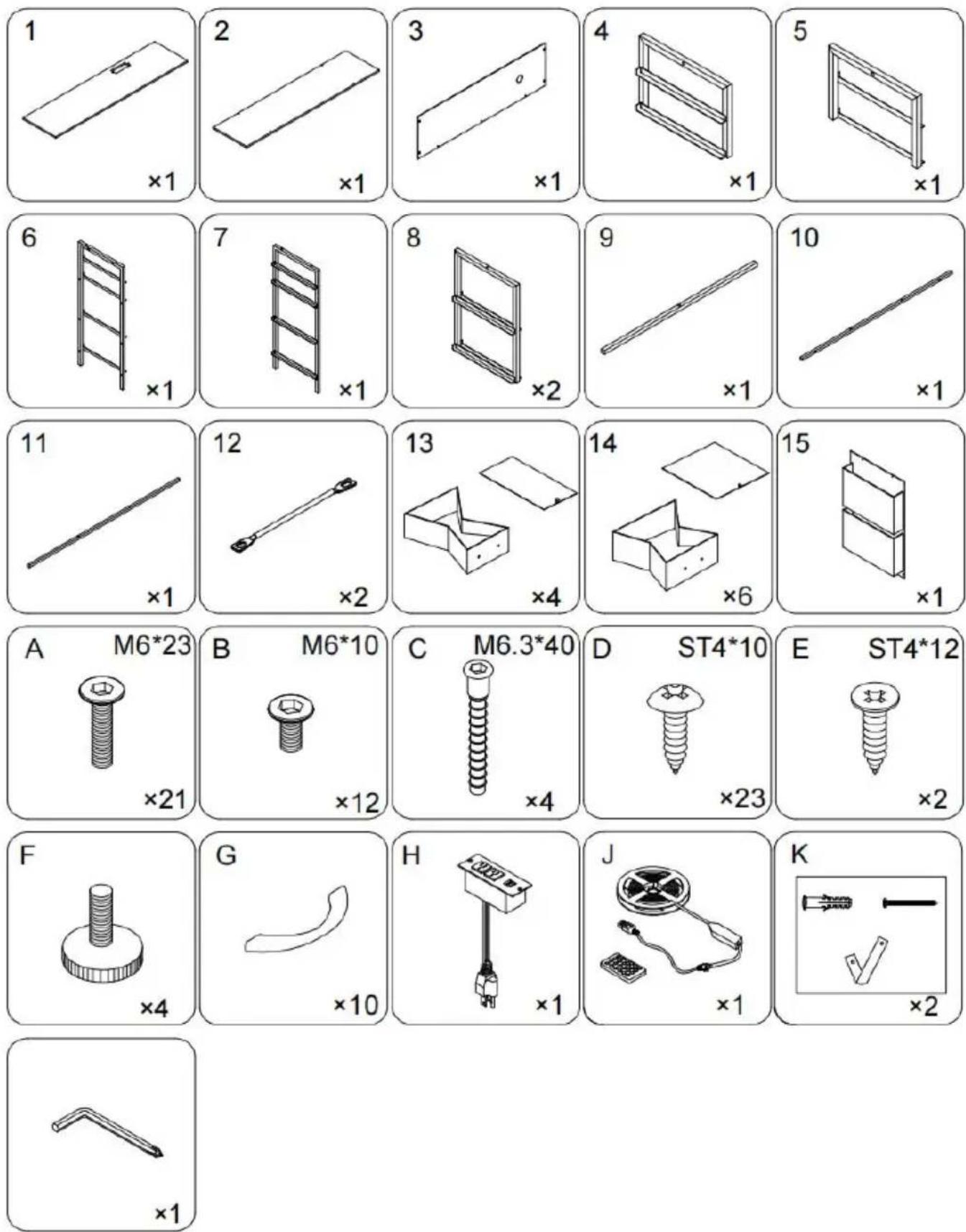
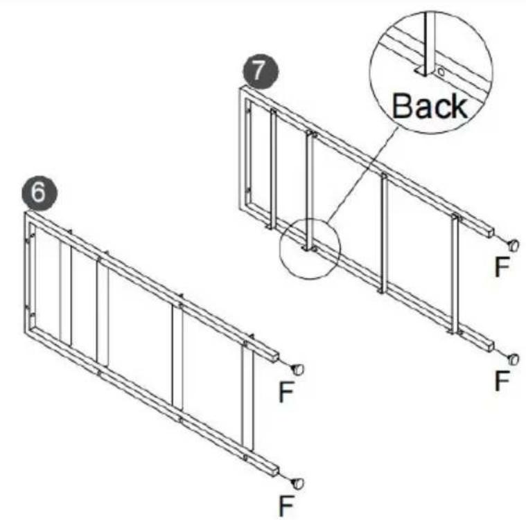
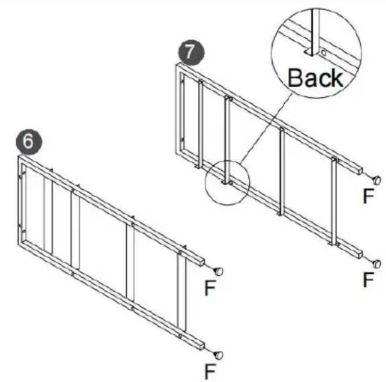
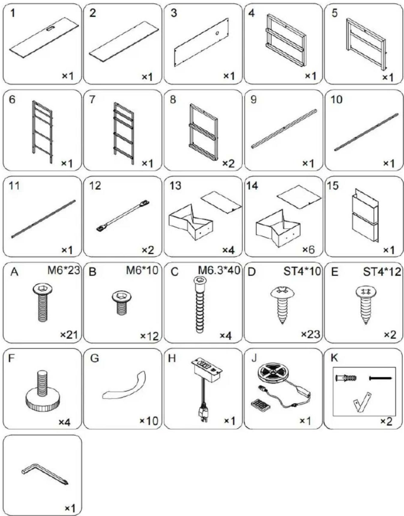
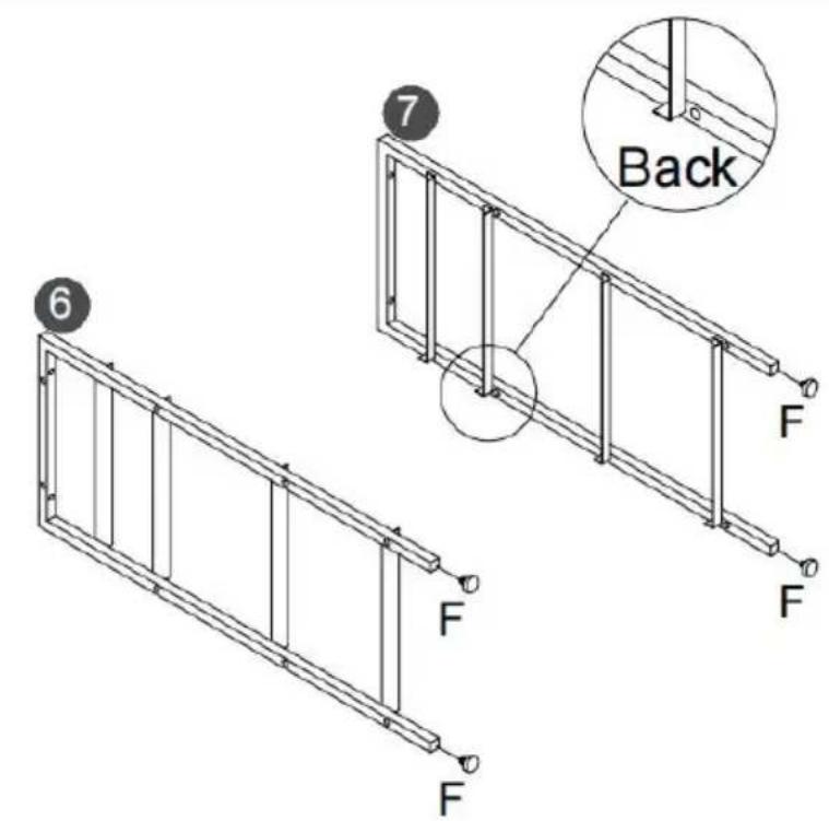
- Because plates and screws are not common, please read the manual carefully before installation, and distinguish each plate and screws.
- Please do not tighten the screws too tightly before installation, and tighten all screws after installation.
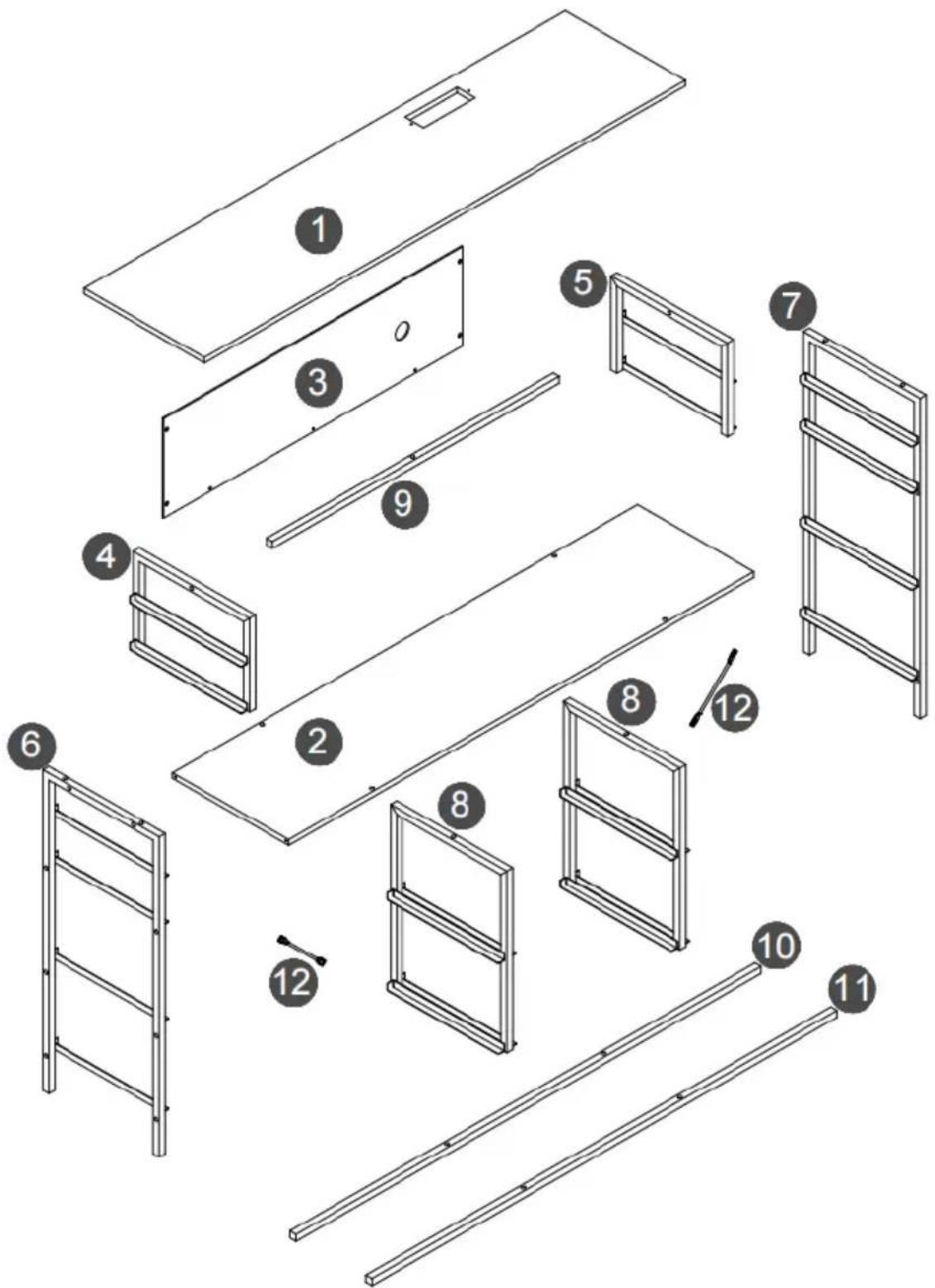
text_image
Exploded view diagram of a furniture or storage unit with numbered components for identification.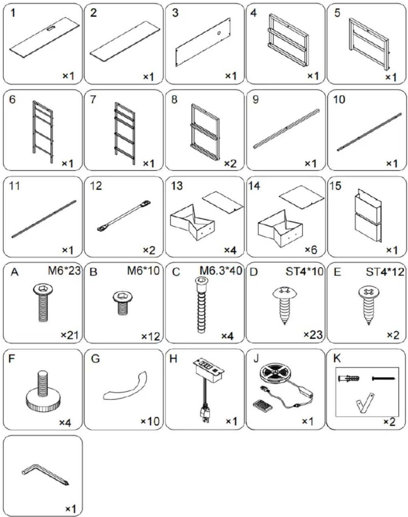
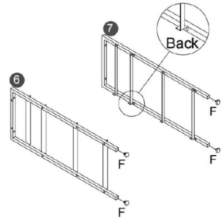
text_image
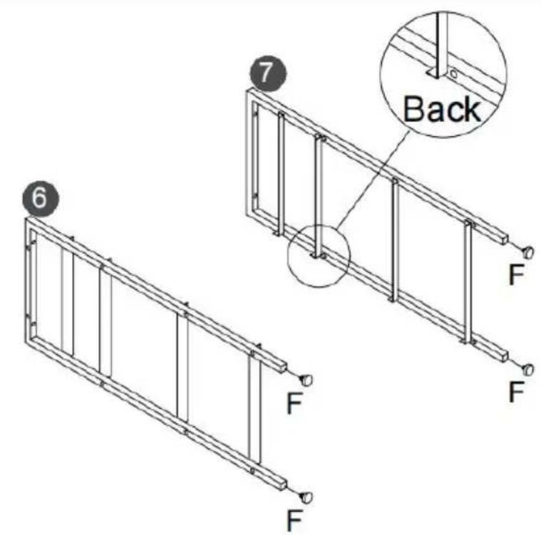
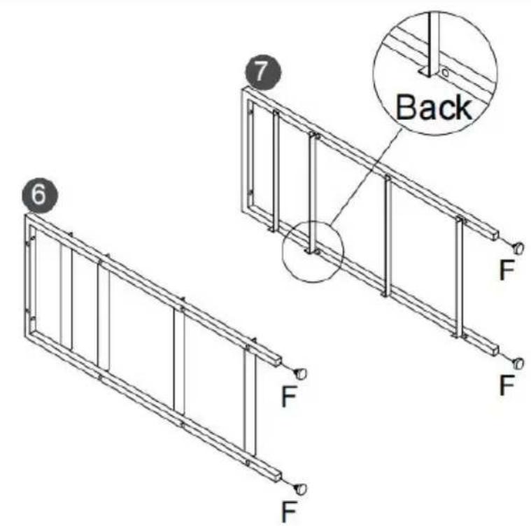
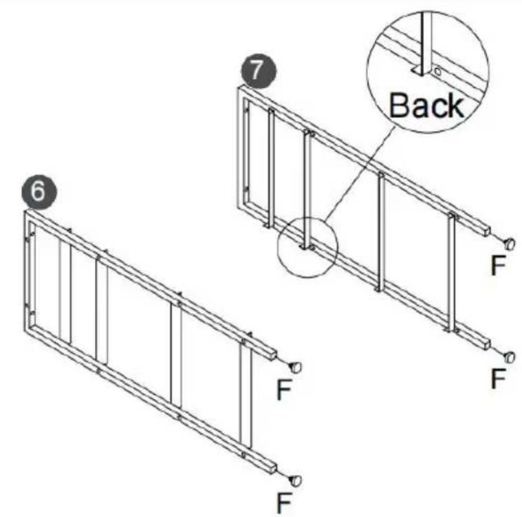
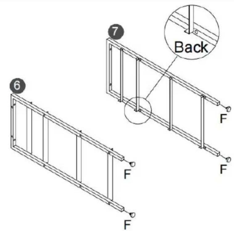
6 7 Back F F F F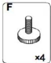
natural_image
Simple 3D-rendered mechanical part with a threaded shaft and circular base, labeled 'F' and 'x4' (no text or symbols on the object itself)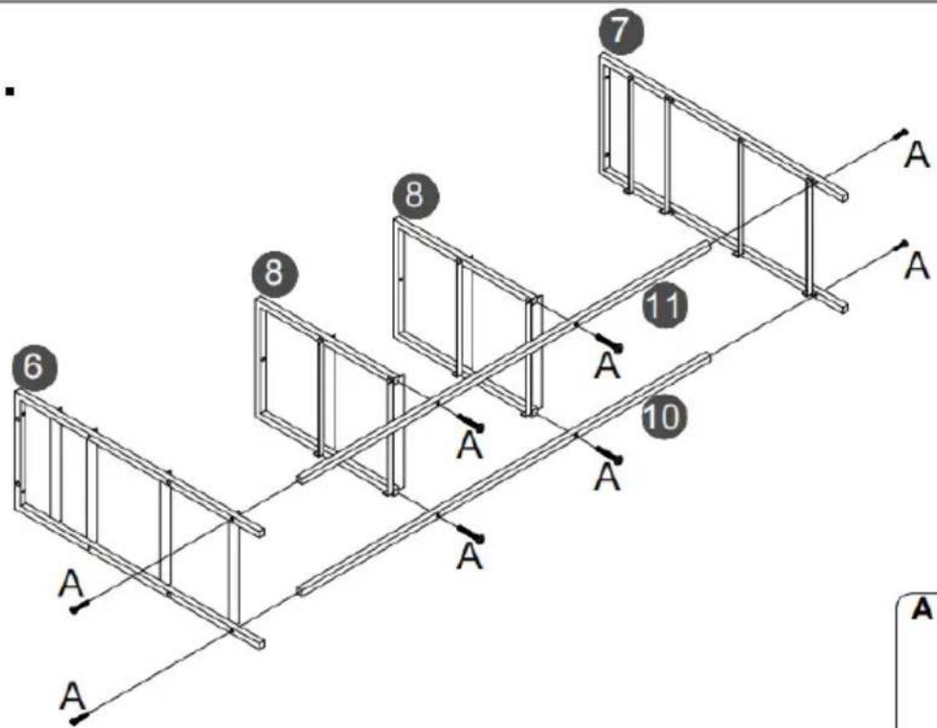
text_image
6 8 7 8 11 10 A A A A A A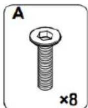
natural_image
Illustration of a screw with hexagonal head and bolt, labeled 'A' and '×8' (no text or symbols on the object itself)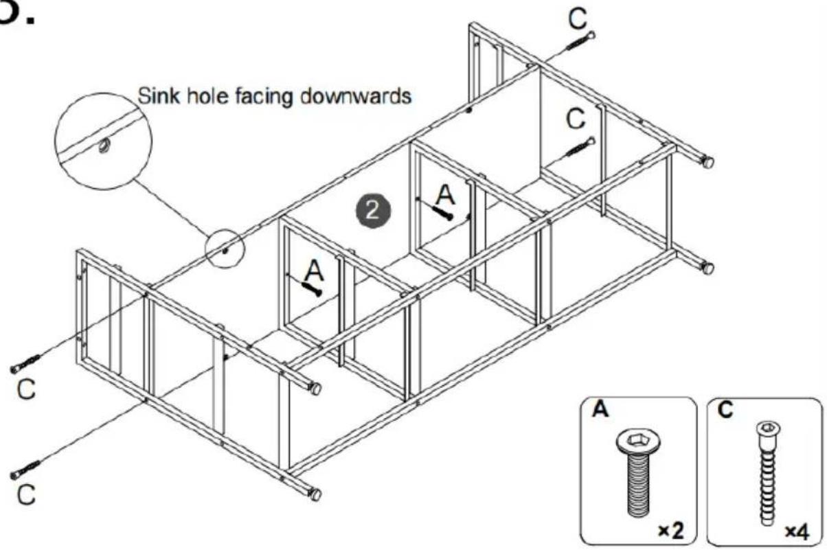
text_image
Sink hole facing downwards A C C 2 A C A ×2 C ×4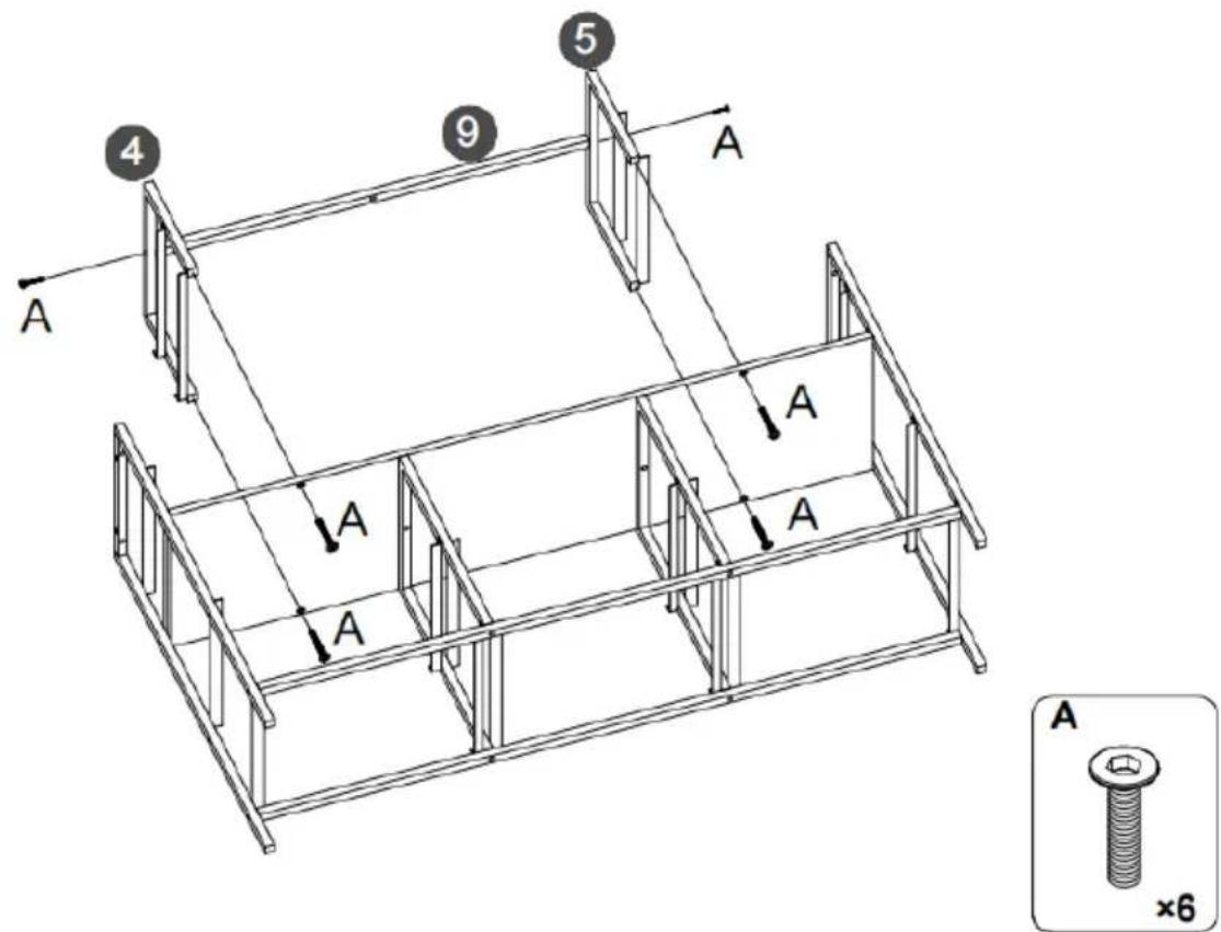
text_image
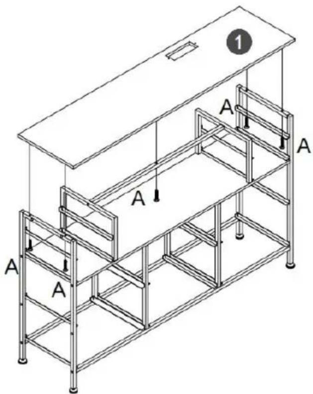
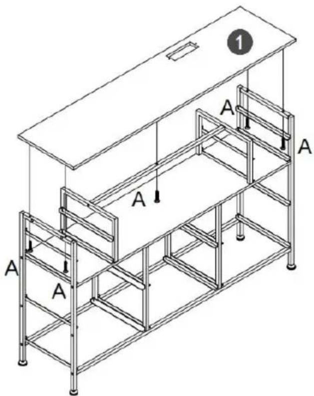
4 9 5 A A A A A A ×65.
text_image
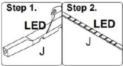
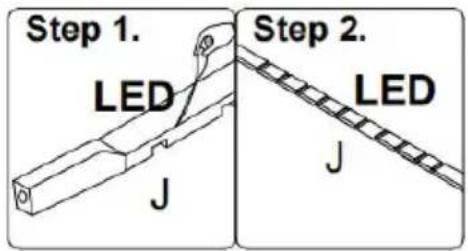
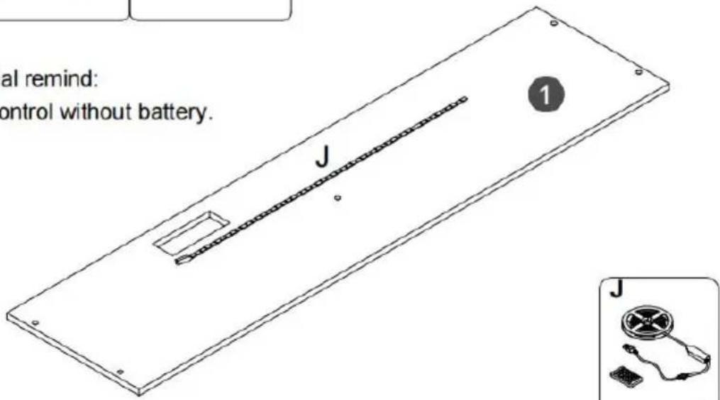
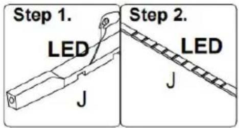
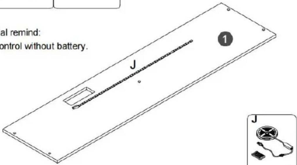
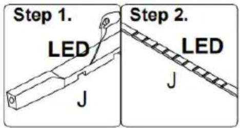
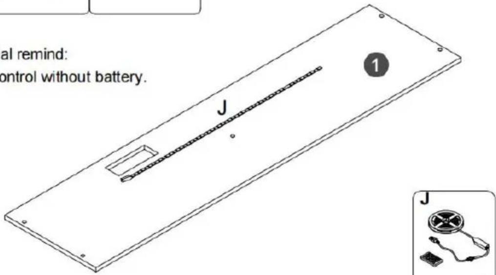
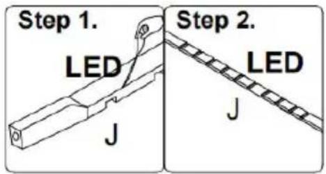
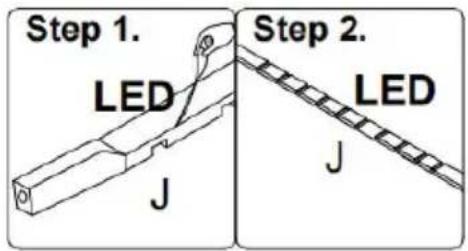
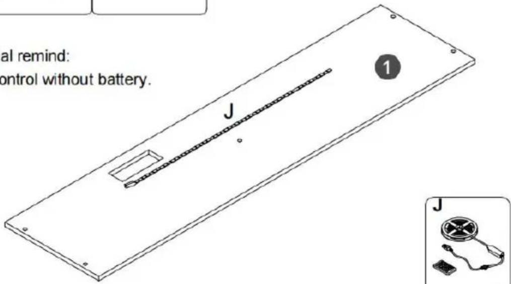
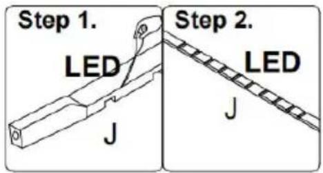
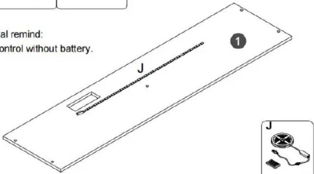
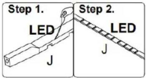
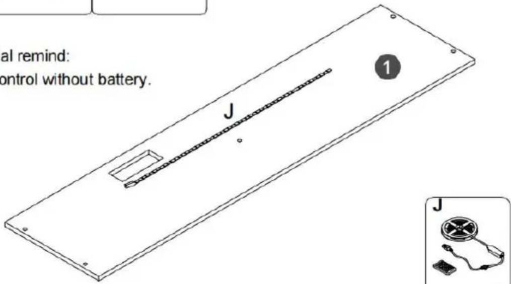
Step 1. LED J Step 2. LED JFirst, Tear off the back adhesive of the the light strip K, and then stick the light strip J to the back of the top plate 1.
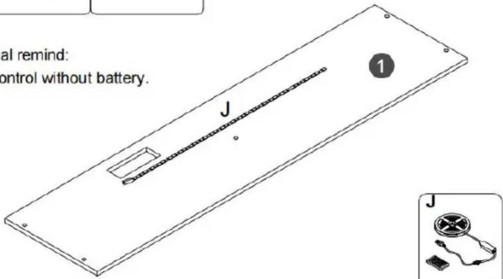
⚠️ Special remind: Remote control without battery.

text_image
al remind: control without battery. J 1 J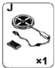
natural_image
Illustration of a handheld electronic device with a spool and connector (no text or symbols)6.

text_image
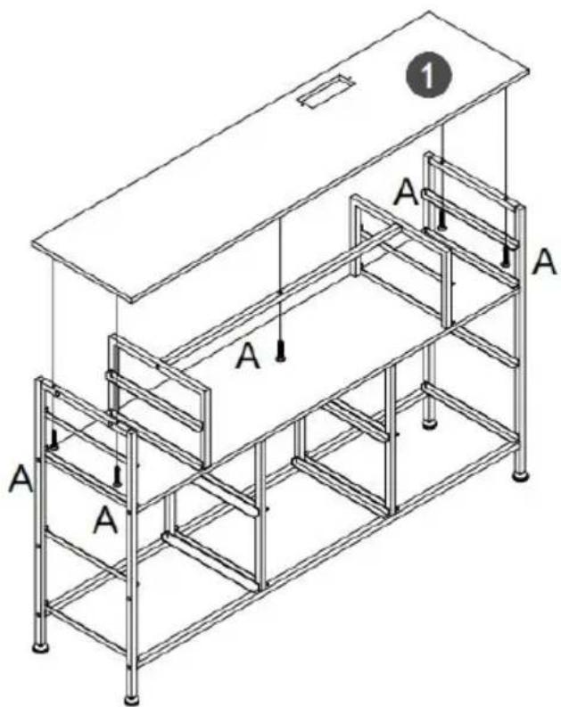
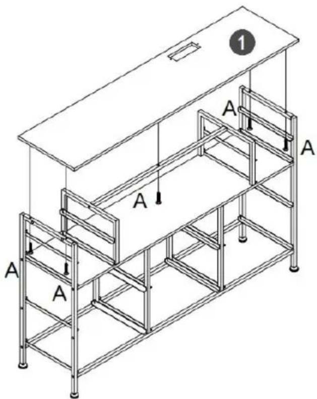
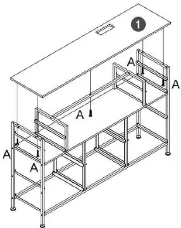
1 A A A A A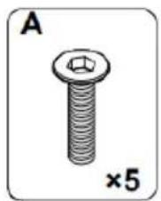
natural_image
Illustration of a bolt with hexagonal head and threaded shaft, labeled 'A' and '×5' (no text or symbols on the object itself)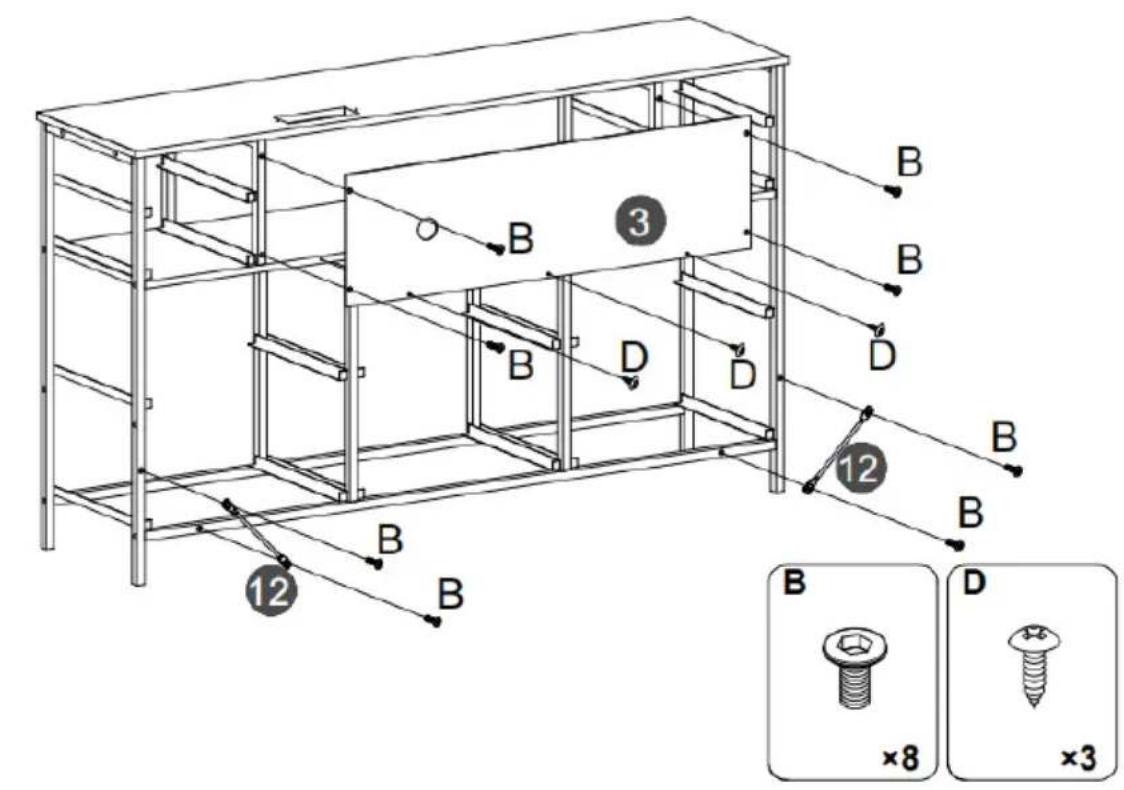
text_image
14 D G x6 14 13 D G x4 13 D ×20 G ×10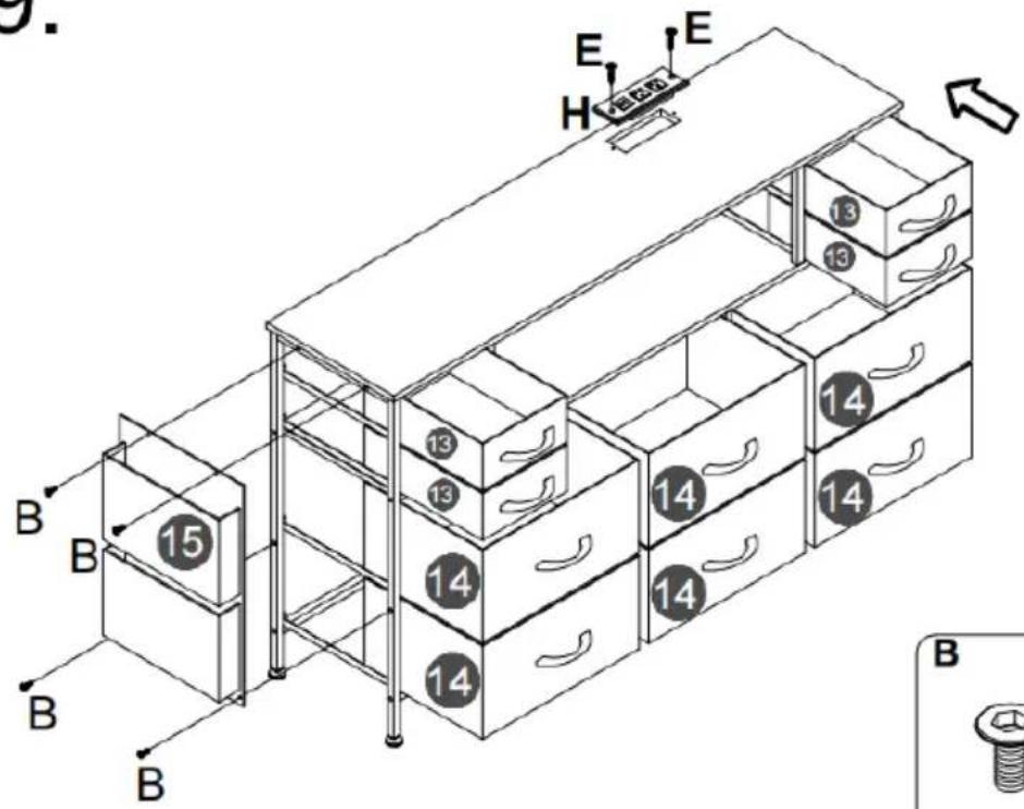
text_image
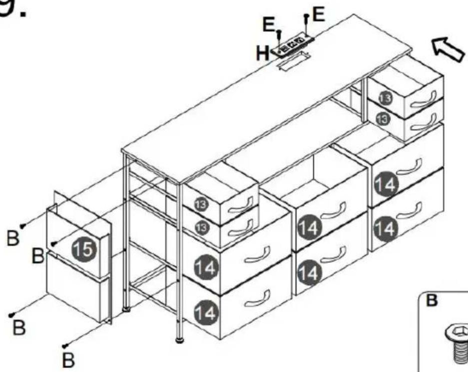
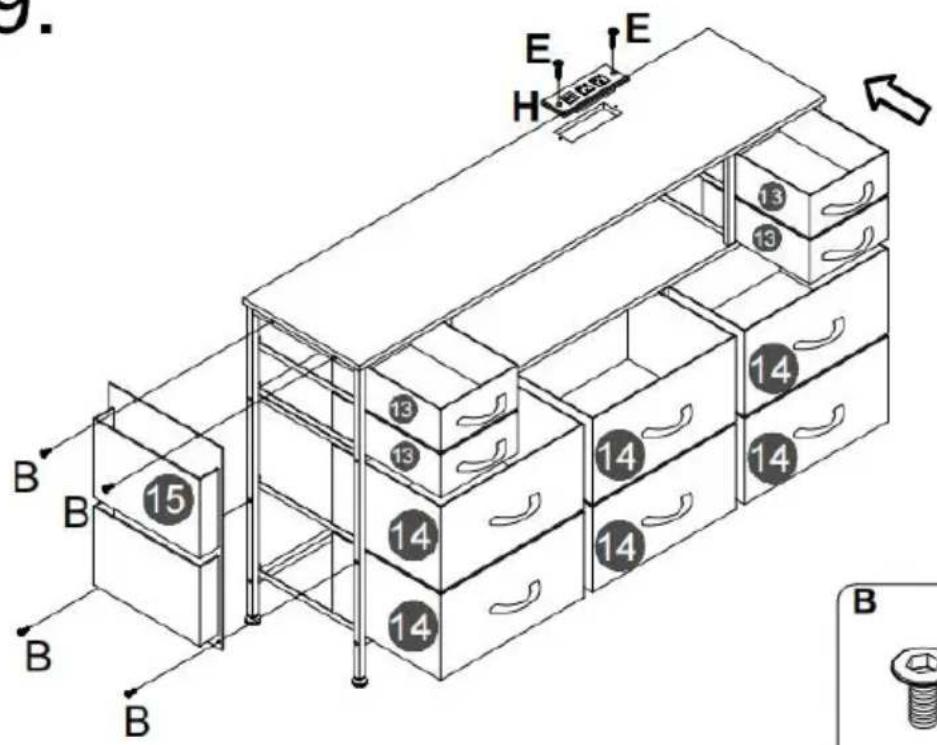
3. E H E 13 13 14 14 14 15 13 13 14 14 14 14 B B B B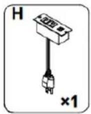
natural_image
Simple diagram of a plug with a connector, labeled 'H' and '×1' (no text or symbols on the diagram itself)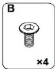
natural_image
Illustration of a hexagonal bolt with a threaded shaft, labeled 'B' and '×4' (no text or symbols on the bolt itself)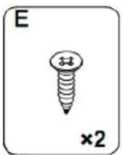
natural_image
Simple line drawing of a screw with a cross mark and '×2' label (no text or symbols on the screw itself)10.
Note:
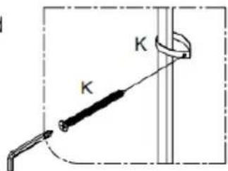
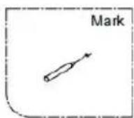
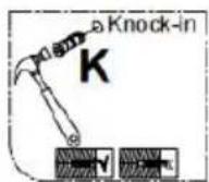
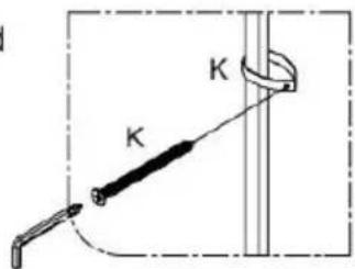
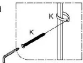
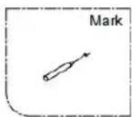
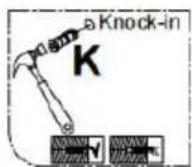
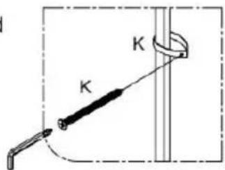
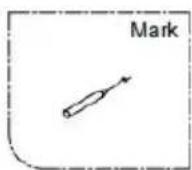
- Mark on the wall
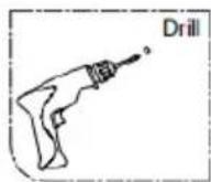
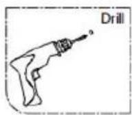
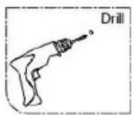
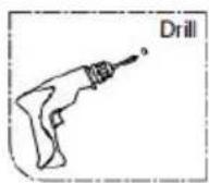
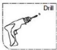
- Use an electric drill to drill deep holes in the wall
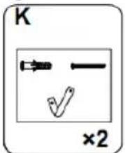
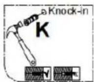
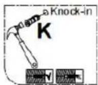
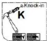
3.Tap part K into the hole

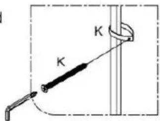
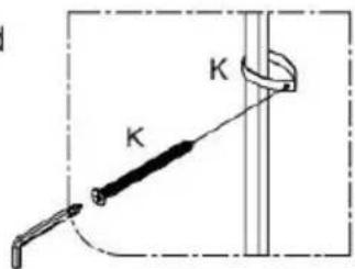
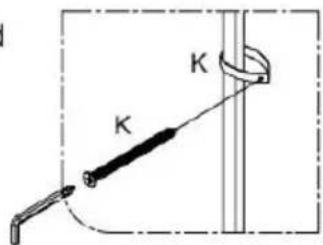
After the cabinet assembly, please install the wall xing device on the back of the cabinet to avoid accidents.

Install at a location based on your needs.

text_image
Diagram showing a mechanical setup with labeled components K and a rod, likely illustrating a motion or assembly process.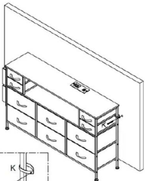
natural_image
Line drawing of a modular shelving unit with drawers and drawers, no text or symbols presentPlease install anti-tip device as following steps if you need
text_image
K ×2RGB LED REMOTE CONTROLLER
● 22 Dynamic Modes
● 20 Static Colors
- Very Smooth Effects
- Speed Adjustable
● Brightness Adjustable
- Card Type RF Remote
- Ultra Slim Design
● Dynamic Demo Mode Easy Remote Pairing - Direct Color Select
Functions:
text_image
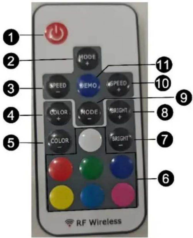
1 2 3 4 5 MODE + SPEED - DEMO - SPEED + COLOR + MODE - BRIGHT + COLOR - BRIGHT - RF Wireless 6 7 8 9 10 111. Turn On/Standby
Press this key to turn on unit or switch to standby mode. At power will automatically turn on and restore to previous status.
2/9. Dynamic Mode Adjust
Switch to dynamic mode from static color, or switch between dynamic modes.
3/10. Dynamic Speed Adjust
Adjust dynamic playing speed, Press 'SPEED+' to increase speed and press 'SPEED-' to decrease. Unit will switch to dynamic mode if press this key at static color mode.
4/5. Static Color Adjust
Switch to static color mode from dynamic mode, or switch between static colors.
6. Direct Color Select
Shortcut key to static colors. When press the specific color key, LED will play the same static color, The direct colors are included in 'COLOR+' and 'COLOR-' operation.
7/8. Brightness Adjust
Adjust static color brightness. Press 'BRIGHT+' to increase brightness and press 'BRIGHT-' to decrease. Unit will switch to static color mode if press this key at dynamic mode.
11. Demo Mode
Press this key will switch to Demo mode. At demo mode, it plays 17 dynamic modes in loop, each mode repeats 3 time.
Installing:
1. Power Supply
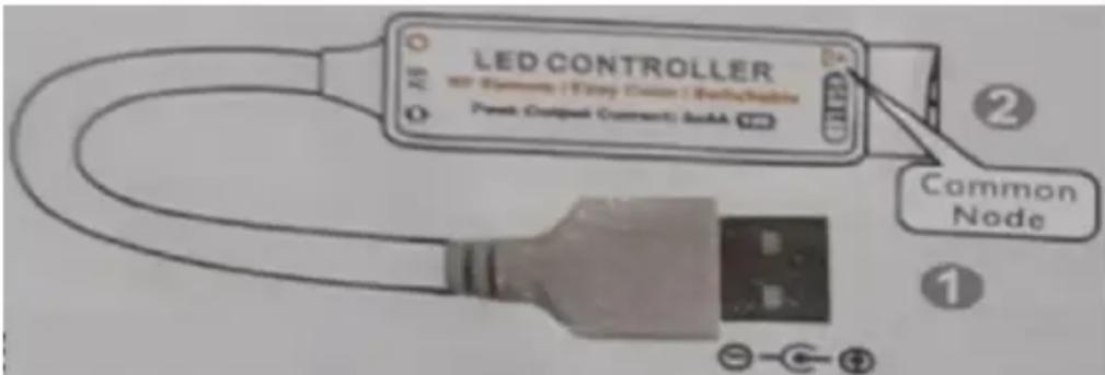
This unit accepts DC 5V to 24V power supply. The DC jack's inner pole (or red cable) is positive and sleeve (or black cable) is negative. Also please make sure the power supply voltage same as the LED load.
\*Note: Remote control without battery.
2.LED Output
This unit support common anode connection LED products. The mark 'A' indicates the common connection node. The peak output current is 4 amperes and maximum constant current is 2 amperes per channel. Please reduce load if main unit is overheating.
CAUTON! Do not short circuit or overload the LED outputs, this may lead to permanent damage!
text_image
LED CONTROLLER INT 500000 | Export Custom | Reputable Power Output (Current) AddA Common Node ① ②Operation:
1. Using Remote Controller
Please pull out the battery insulate tape before using. The RF wireless remote signal can pass through barrier, so it's not necessary to aim at the main unit when operate. For proper receiving remote signal, please do not install the main unit in closed metal parts.
2. Pairing New Remote
The remote and main unit is 1 to 1 paired as default, Furthermore, main unit can be paired to 3 remote controllers and each remote controller can be paired to any main unit Please do following steps to pair new remote controller.
1) Plug off the power of main unit and plug in after S seconds.
2) Press 'On/off' and 'BRIGHT-' key together in 5 seconds after power on. After this operation, the main unit will recognize the new remote controller.
3. Free Remote Pairing Mode
In some specific cases; the main unit may need to be paired to any remote controllers. Please do following steps for free remote pairing mode:
1) Plug off the power of main unit and plug in after 5 seconds.
2) Press 'ON/OFF' and 'MODE+' key together in 5 seconds after power on. After this operation, the main unit will recognize any remote controller. To pair the main unit back to specific remote, please repeat the 'Pairing New Remote' operation.
4. Switch Output Color Sequence
The controller's default output signal sequence is Common-Green-Red-Blue. If the LED application is in different cable sequence, the direct color keys will not match the LED color. In this case, user can adjust the output signal sequence with following steps:
1) Plug off the power of main unit and plug in after 5 seconds.
2) Press 'RED' and 'BLUE' color key together in 5 seconds after power on. With this operation, the output sequence will switch between 6 possible combinations. The sequence will be memorized and it won't change before
next same operation.
FCC INFORMATION
CAUTION: Changes or modifications not expressly approved by the party responsible for compliance could void the user's authority to operate the equipment!
This device complies with Part 15 of the FCC Rules. Operation is subject to the following two conditions:
1) This product may cause harmful interference.
2) This product must accept any interference received, including interference that may cause undesired operation.
WARNING: Changes or modifications not expressly approved by the party responsible for compliance could void the user's authority to operate the equipment.
NOTE: This equipment has been tested and found to comply with the limits for a Class B digital device, pursuant to Part 15 of the FCC Rules. These limits are designed to provide reasonable protection against harmful interference in a residential installation. This unit generates, uses, and can radiate radio frequency energy and if not installed and used in accordance with the instructions, may cause harmful interference to radio communications. However, there is no guarantee that interference will not occur in a particular installation. If this equipment does cause harmful interference to radio or television reception, which can be one or more of the following measures:
● Reorient or relocate the receiving antenna.
- Increase the separation between the equipment and receiver.
- Connect the equipment to an outlet on a circuit different from that to which the receiver is connected.
- Consult the dealer or an experienced radio/TV technician for help.
PRODUCT PARAMETER
| Model | ZWE-BC-SS-07ZWE-BC-SS-09 | ZWE-BC-SS-08ZWE-BC-SS-10 |
| Sockets | Model: JN02-03-22125VAC,12A, 60Hz1500W | Model: JN02-00-22220~250VAC,50/60HzMax.16A |
| USB Port | 5VDC, Max. 2A,Max. 10W | 5VDC, Max. 2.1A,Max. 10.5W |
| Colour | Black | |
| Safe Loading Weight | 5kg/Grid (Large) & 2.5kg/Grid (Small) | |
| Product Size | 1200*300*720mm | |
| LED Remote Controller | ||
| Dynamic mode | 22 modes | |
| Static Color | 20 colors | |
| PWM Grade | 256 levels | |
| Brightness Grade | 5 levels | |
| Speed Grade | 10 levels | |
| Demo mode | Yes | |
| Direct Color Select | Yes | |
| Output Color Switchable | Yes, 6 options | |
| Working Voltage | DC 5~24V | |
| Output Current | 3x4A peak, 3x2A constant | |
| Remote frequency | 433.92MHz | |
Manufacturer: Shanghaimuxinmuyeyouxiangongsi
Address: Shuangchenglu 803nong11hao1602A-1609shi, baoshanqu, shanghai 200000 CN.
Imported to AUS: SIHAO PTY LTD. 1 ROKEVA STREETEASTWOOD NSW 2122 Australia
Imported to USA: Sanven Technology Ltd. Suite 250, 9166 Anaheim Place, Rancho Cucamonga, CA 91730
| EC | REP |
E-CrossStu GmbH
Mainzer Landstr.69, 60329 Frankfurt am Main.
| UK | REP |
YH CONSULTING LIMITED.
C/O YH Consulting Limited Office 147, Centurion
House, London Road, Staines-upon-Thames, Surrey, TW18 4AX
VEVOR®
TOUGH TOOLS, HALF PRICE
Technical Support and E-Warranty Certificate
www.vevor.com/support
VEVOR®
TOUGH TOOLS, HALF PRICE
natural_image
Line drawing of a multi-level office drawer cabinet with drawers and handlebars (no text or symbols)POTRZEBUJESZ POMOCY? SKONTAKTUJ SIĘ Z NAMI!
www.vevor.com/support
- Because plates and screws are not common, please read the manual carefully before installation, and distinguish each plate and screws.
- Please do not tighten the screws too tightly before installation, and tighten all screws after installation.
text_image
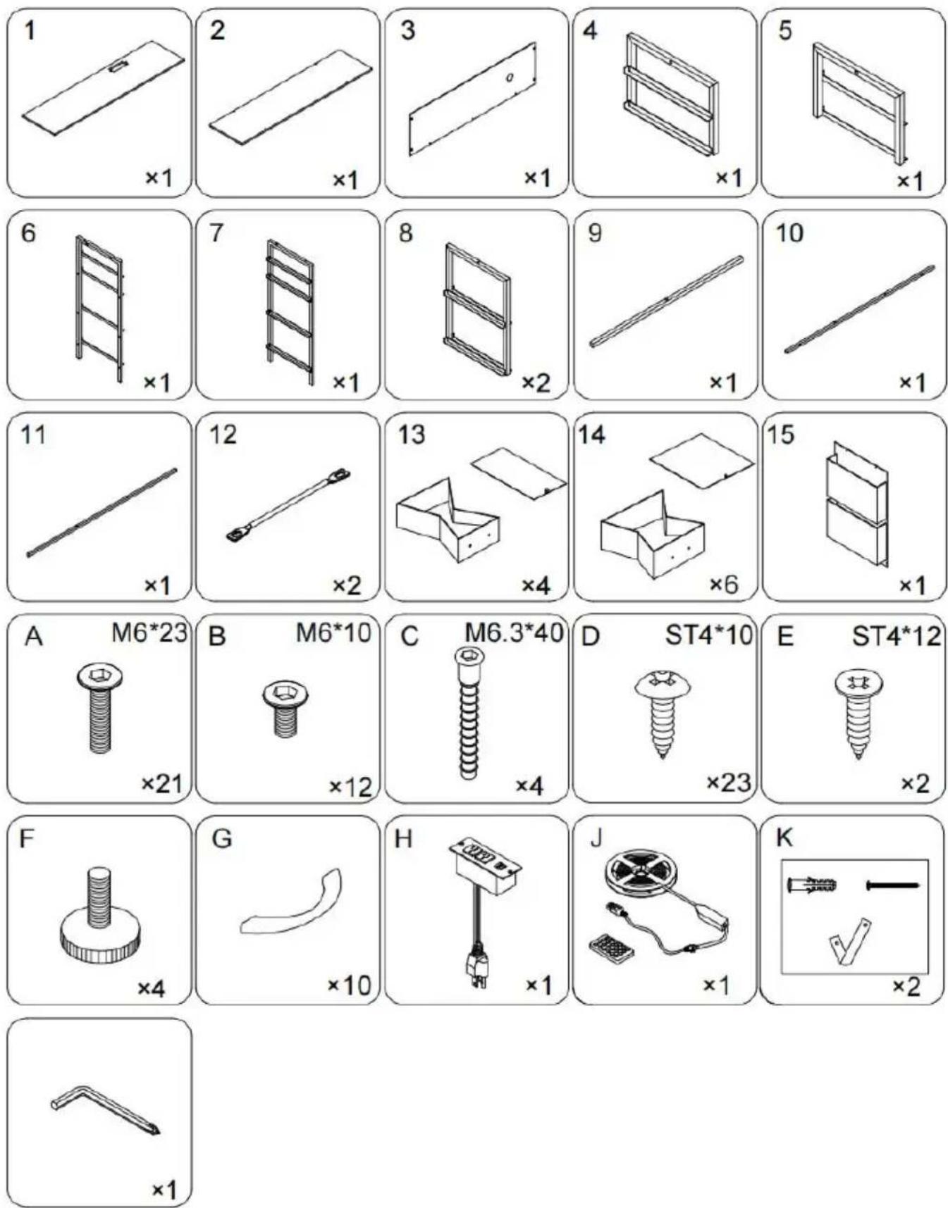
Technical diagram showing 12 labeled components of a folding or folding assembly, including horizontal and vertical metal frames.PARTS LIST
text_image
6 7 Back F F F F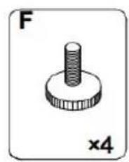
natural_image
Simple line drawing of a screw-like mechanical component (no text or symbols)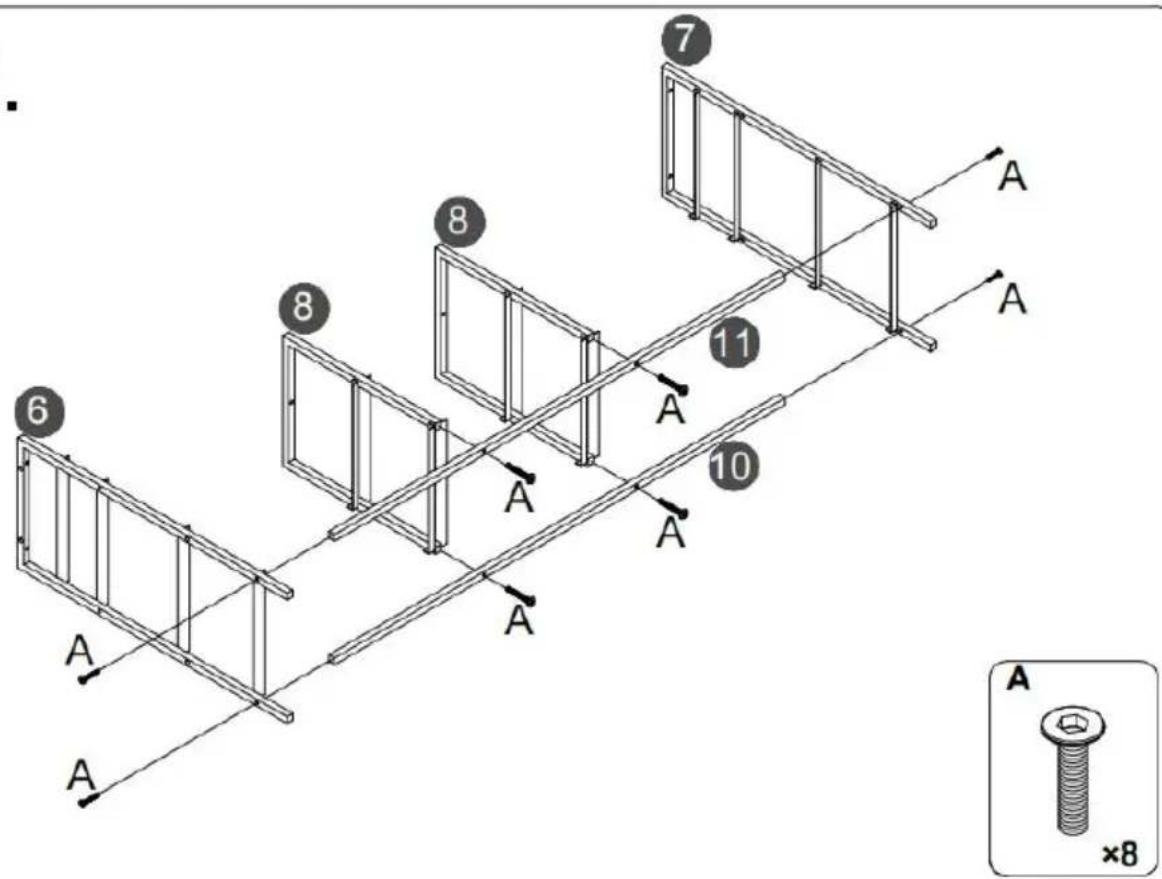
text_image
7 8 11 6 8 10 A A A A A A A A A ×8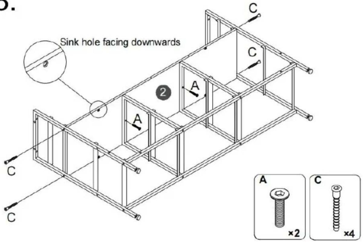
text_image
Sink hole facing downwards A C C 2 A C A ×2 ×4 C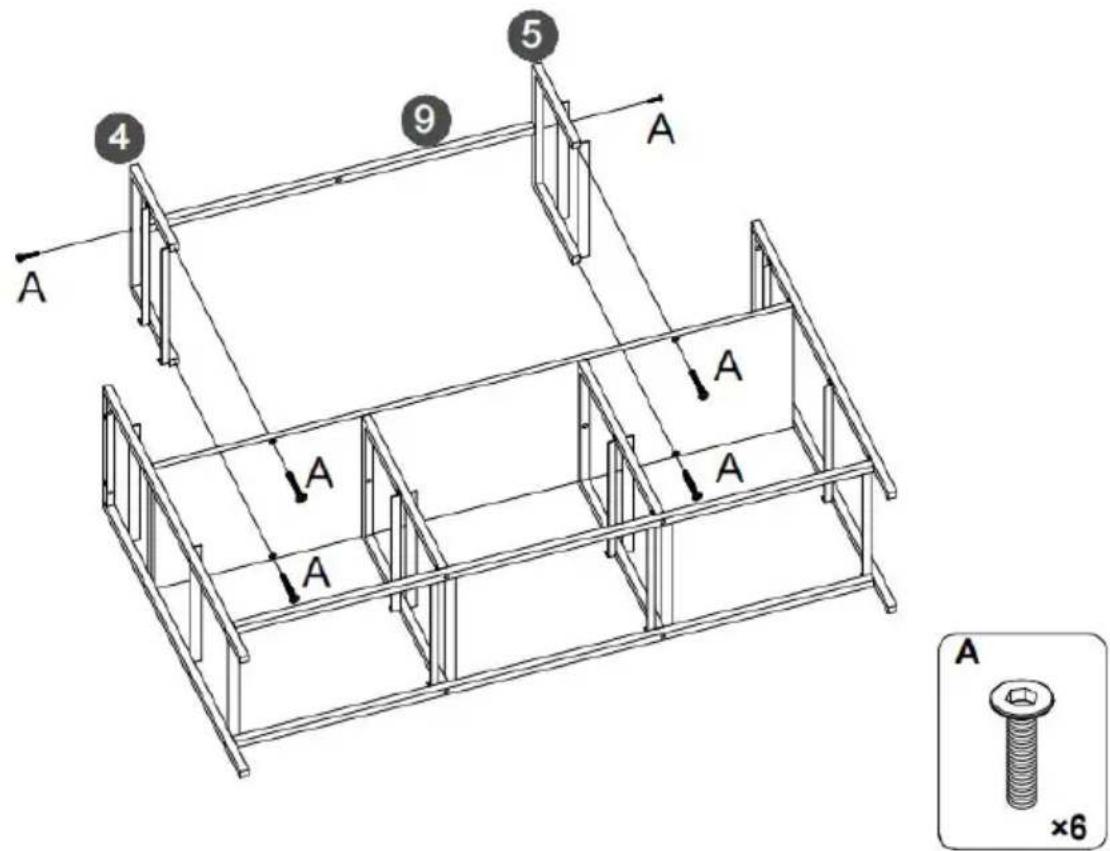
text_image
4 9 5 A A A A A A ×65.
text_image
Step 1. LED J Step 2. LED JFirst, Tear off the back adhesive of the the light strip K, and then stick the light strip J to the back of the top plate 1.
⚠️ Special remind: Remote control without battery.
text_image
al remind: control without battery. J 1 J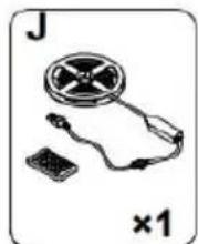
natural_image
Illustration of a handheld electronic device with a circular component and a small rectangular base, labeled 'J' and '×1' (no text or symbols on the device itself)6.
text_image
1 A A A A A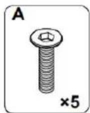
natural_image
Illustration of a bolt with a hexagonal nut, labeled 'A' and '×5' (no text or symbols on the bolt itself)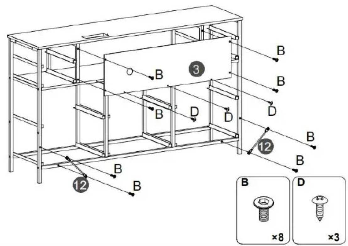
text_image
14 D G x6 14 13 D G x4 13 D ×20 G ×10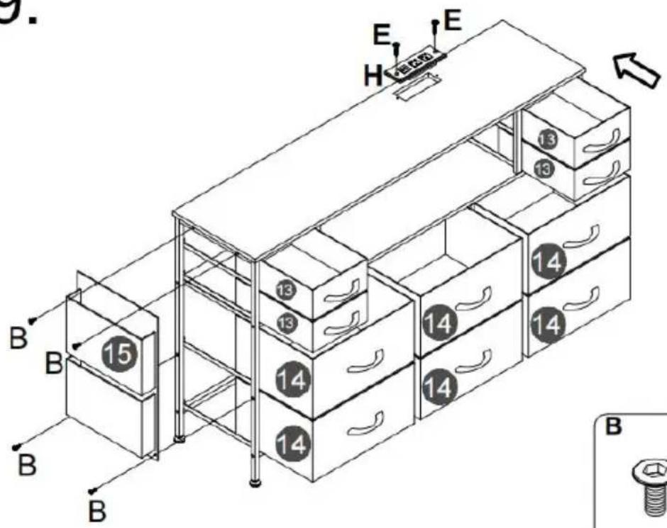
natural_image
Simple diagram of a device with a plug and connector, labeled 'H' and '×1' (no text or symbols on the diagram itself)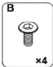
natural_image
Illustration of a bolt with hexagonal nut and cross symbol, labeled 'B' and '×4' (no text or symbols on the bolt itself)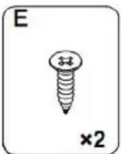
natural_image
Simple line drawing of a screw with a cross mark and '×2' label (no text or symbols on the screw itself)10.
Note:
- Mark on the wall
- Use an electric drill to drill deep holes in the wall
- Tap part K into the hole

After the cabinet assembly, please install the wall xing device on the back of the cabinet to avoid accidents.

Install at a location based on your needs.
text_image
Diagram showing a mechanical setup with labeled components K and a curved component, likely illustrating a motion or assembly.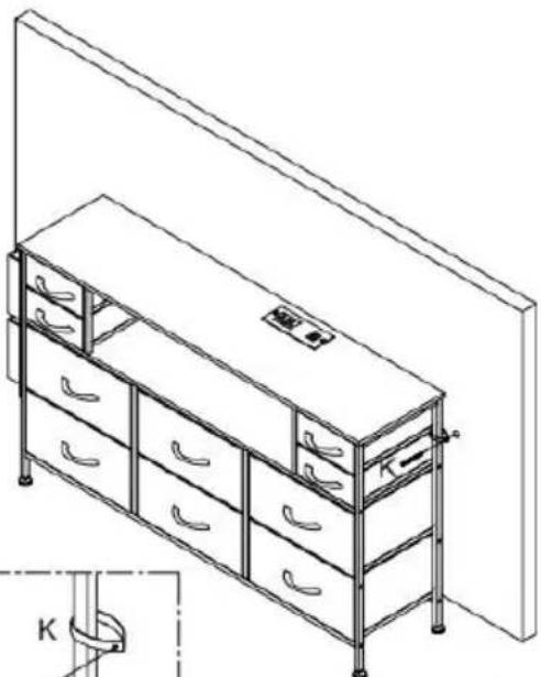
natural_image
Line drawing of a multi-level office cabinet with drawers and storage racks, no text or symbols present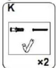
text_image
K ×2Please install anti-tip device as following steps if you need
RGB LED REMOTE CONTROLLER
STREETEASTWOOD NSW 2122 Australia
Importowane do USA: Sanven Technology Ltd. Suite 250, 9166 Anar Place, Rancho Cucamonga, CA 91730
| EC | REP |
E-CrossStu GmbH
Mainzer Landstr.69, 60329 Frankfurt am Main
| UK | REP |
YH CONSULTING LIMITED.
C/O YH Consulting Limited Office 147, Centurion House, London Road, Staines-upon-Thames, Surrey TW18 4AX
VEVOR®
TOUGH TOOLS, HALF PRICE
www.vevor.com/support
VEVOR®
TOUGH TOOLS, HALF PRICE
www.vevor.com/support
KOMMODE MIT STOFFSCHUBLADE
Benutzerhandbuch
MODELL: ZWE-BC-SS-0 7 / ZWE-BC-SS-08
ZWE-BC-SS-0 9/ ZWE-BC-SS-10
natural_image
Line drawing of a multi-level office drawer cabinet with drawers and handlebars (no text or symbols)www.vevor.com/support
- Because plates and screws are not common, please read the manual carefully before installation, and distinguish each plate and screws.
- Please do not tighten the screws too tightly before installation, and tighten all screws after installation.
text_image
Technical diagram showing 12 labeled components of a folding or folding assembly, including horizontal and vertical metal frames.PARTS LIST
text_image
6 7 Back F F F F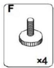
natural_image
Simple line drawing of a screw-like mechanical component (no text or symbols)
text_image
7 8 11 6 8 10 A A A A A A A A A ×8
text_image
Sink hole facing downwards A C C 2 A C A ×2 ×4 C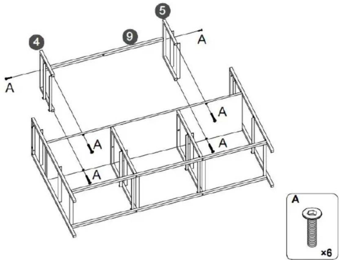
text_image
4 9 5 A A A A A A ×65.
text_image
Step 1. LED J Step 2. LED JFirst, Tear off the back adhesive of the the light strip K, and then stick the light strip J to the back of the top plate 1.
⚠️ Special remind: Remote control without battery.
text_image
al remind: control without battery. J 1 J
natural_image
Illustration of a handheld electronic device with a circular component and a small rectangular base, labeled 'J' and '×1' (no text or symbols on the device itself)6.
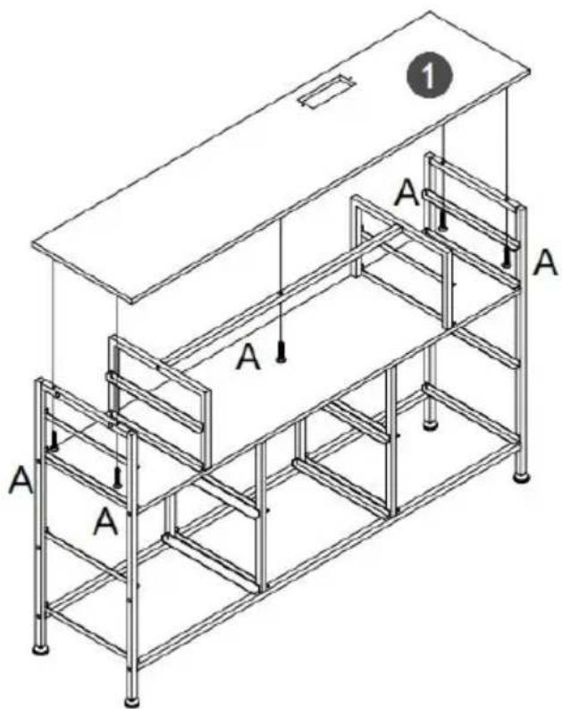
text_image
1 A A A A A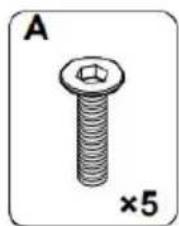
natural_image
Illustration of a bolt with a hexagonal nut, labeled 'A' and '×5' (no text or symbols on the bolt itself)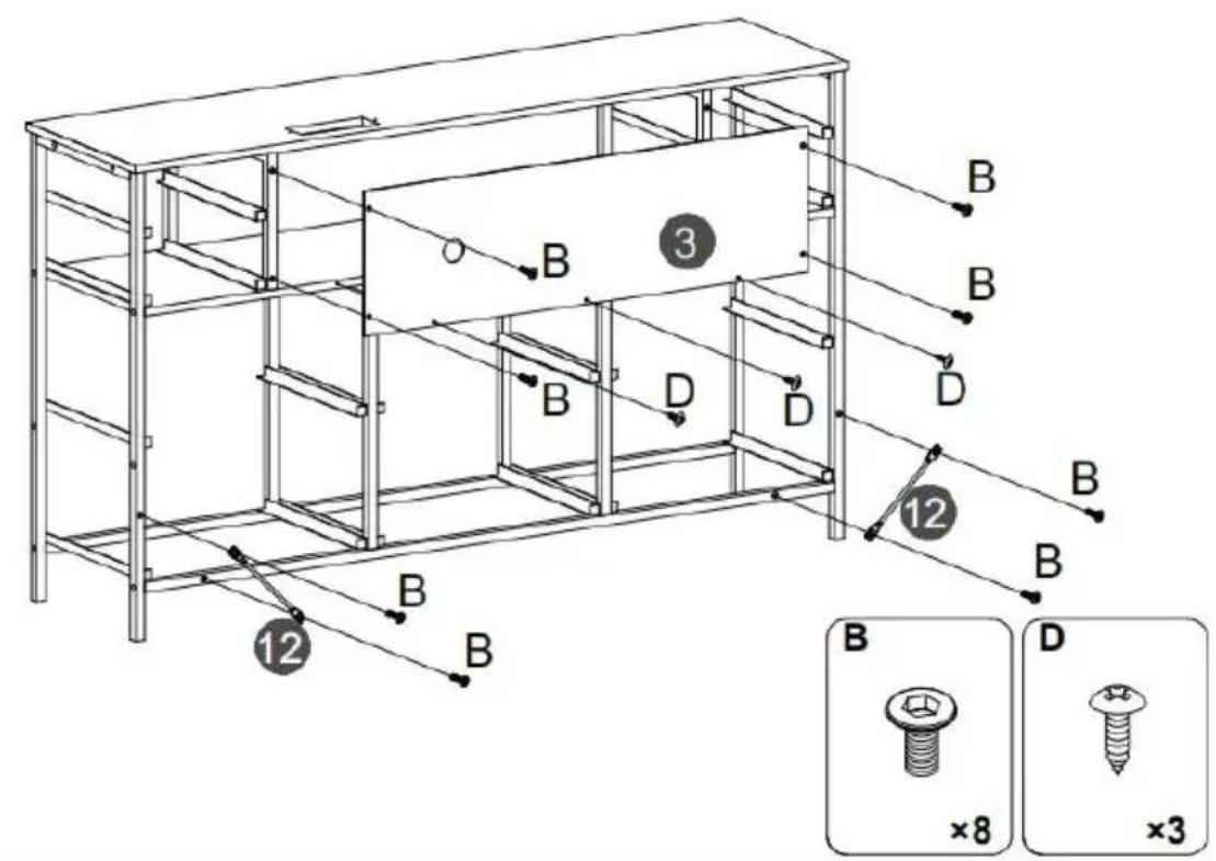
text_image
Technical diagram of a multi-level storage unit with labeled components and assembly details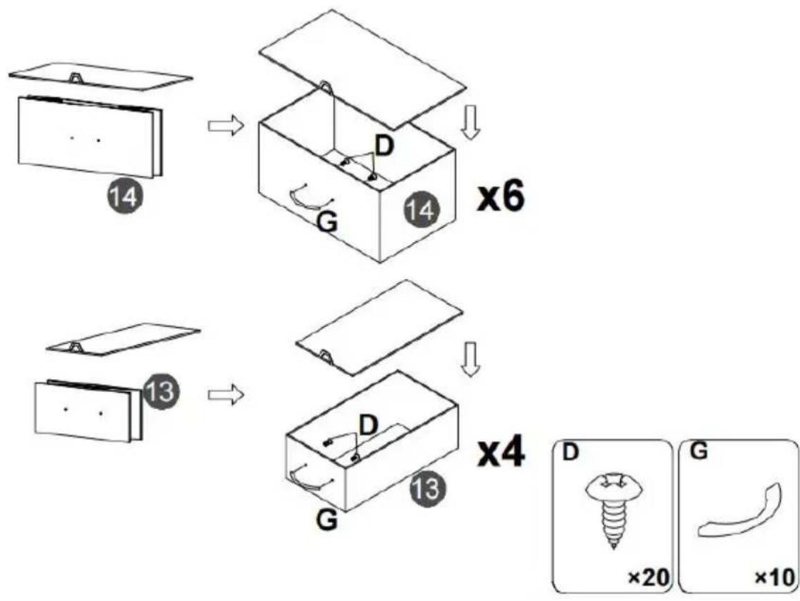
text_image
14 D G x6 14 13 D G x4 13 D ×20 G ×10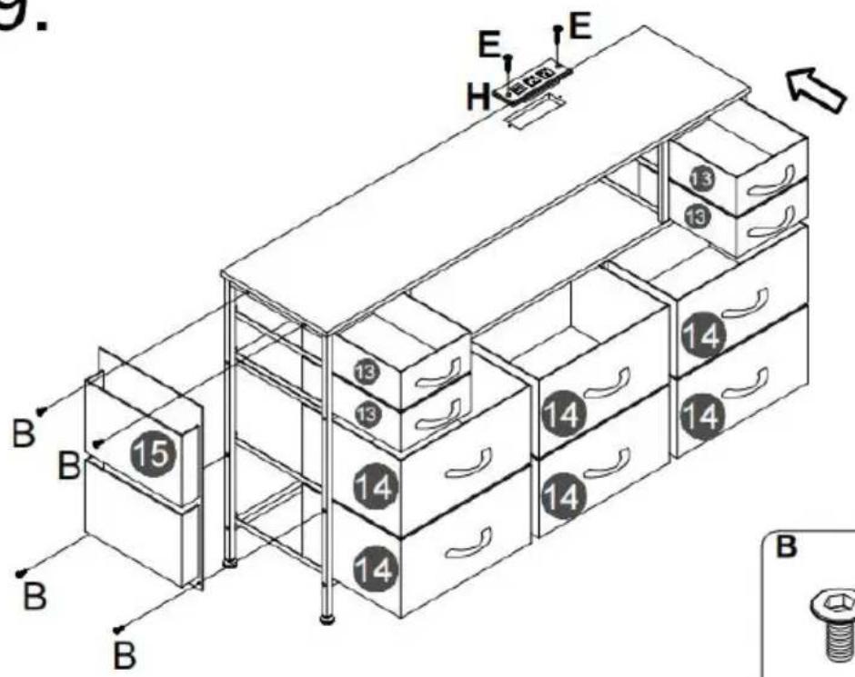
natural_image
Simple diagram of a device with a plug and connector, labeled 'H' and '×1' (no text or symbols on the diagram itself)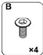
natural_image
Illustration of a bolt with hexagonal nut and cross symbol, labeled 'B' and '×4' (no text or symbols on the bolt itself)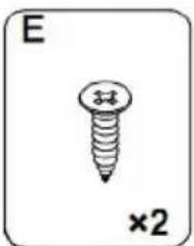
natural_image
Simple line drawing of a screw with a cross mark and '×2' label (no text or symbols on the screw itself)10.
Note:
- Mark on the wall
- Use an electric drill to drill deep holes in the wall
- Tap part K into the hole

After the cabinet assembly, please install the wall xing device on the back of the cabinet to avoid accidents.

Install at a location based on your needs.
text_image
Diagram showing a mechanical setup with labeled components K and a curved component, likely illustrating a motion or assembly.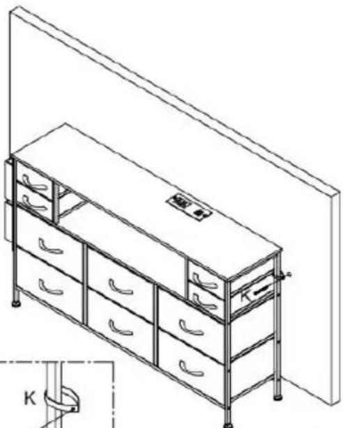
natural_image
Line drawing of a multi-level office cabinet with drawers and storage racks, no text or symbols present
text_image
K ×2Please install anti-tip device as following steps if you need
RGB LED REMOTE CONTROLLER
text_image
LED CONTROLLER INT Ethernet / Ethernet Connection / Normalization Power Output Current: 244A Common Node ① ②Bedienung :
C/O YH Consulting Limited Office 147, Centurion House, London Road, Staines-upon-Thames, Surrey TW18 4AX
VEVOR®
TOUGH TOOLS, HALF PRICE
www.vevor.com/support
VEVOR®
TOUGH TOOLS, HALF PRICE
natural_image
Line drawing of a multi-level office drawer cabinet with drawers and handlebars (no text or symbols)BESOIN D'AIDE? CONTACTEZ-NOUS!
- Because plates and screws are not common, please read the manual carefully before installation, and distinguish each plate and screws.
- Please do not tighten the screws too tightly before installation, and tighten all screws after installation.
text_image
Technical diagram showing 12 numbered components of a folding or folding assembly, including horizontal and vertical metal frames.PARTS LIST
text_image
6 7 Back F F F F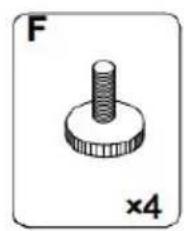
natural_image
Simple line drawing of a screw-like mechanical component (no text or symbols)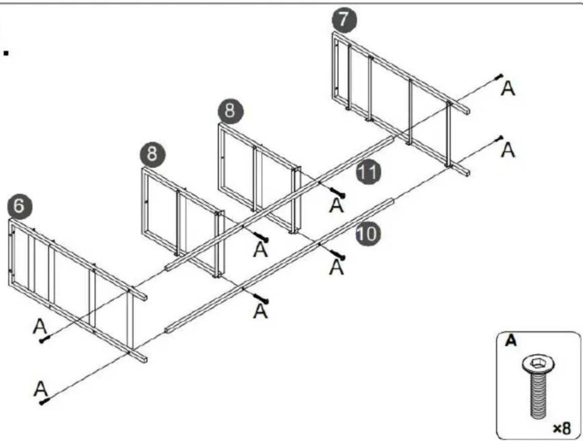
text_image
7 8 11 6 8 10 A A A A A A A A A ×8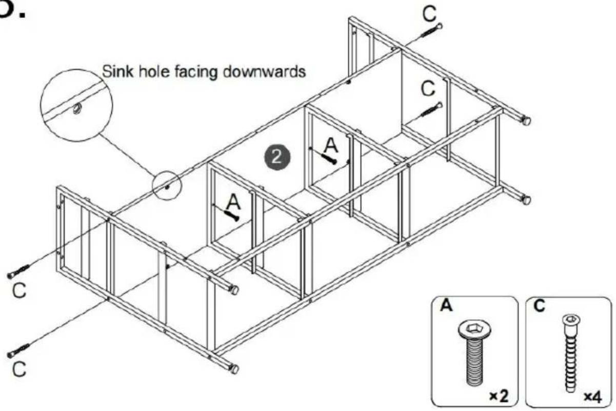
text_image
Sink hole facing downwards A C C 2 A C A ×2 ×4 C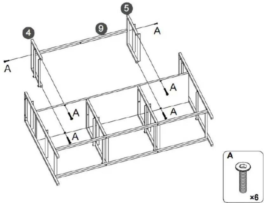
text_image
4 9 5 A A A A A A ×65.
text_image
Step 1. LED J Step 2. LED JFirst, Tear off the back adhesive of the the light strip K, and then stick the light strip J to the back of the top plate 1.
⚠️ Special remind: Remote control without battery.
text_image
al remind: control without battery. J 1 J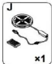
natural_image
Illustration of a handheld electronic device with a circular component and a small rectangular base, labeled 'J' and '×1' (no text or symbols on the device itself)6.
text_image
1 A A A A A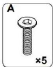
natural_image
Illustration of a bolt with a hexagonal head and threaded shaft, labeled 'A' and '×5' (no text or symbols on the object itself)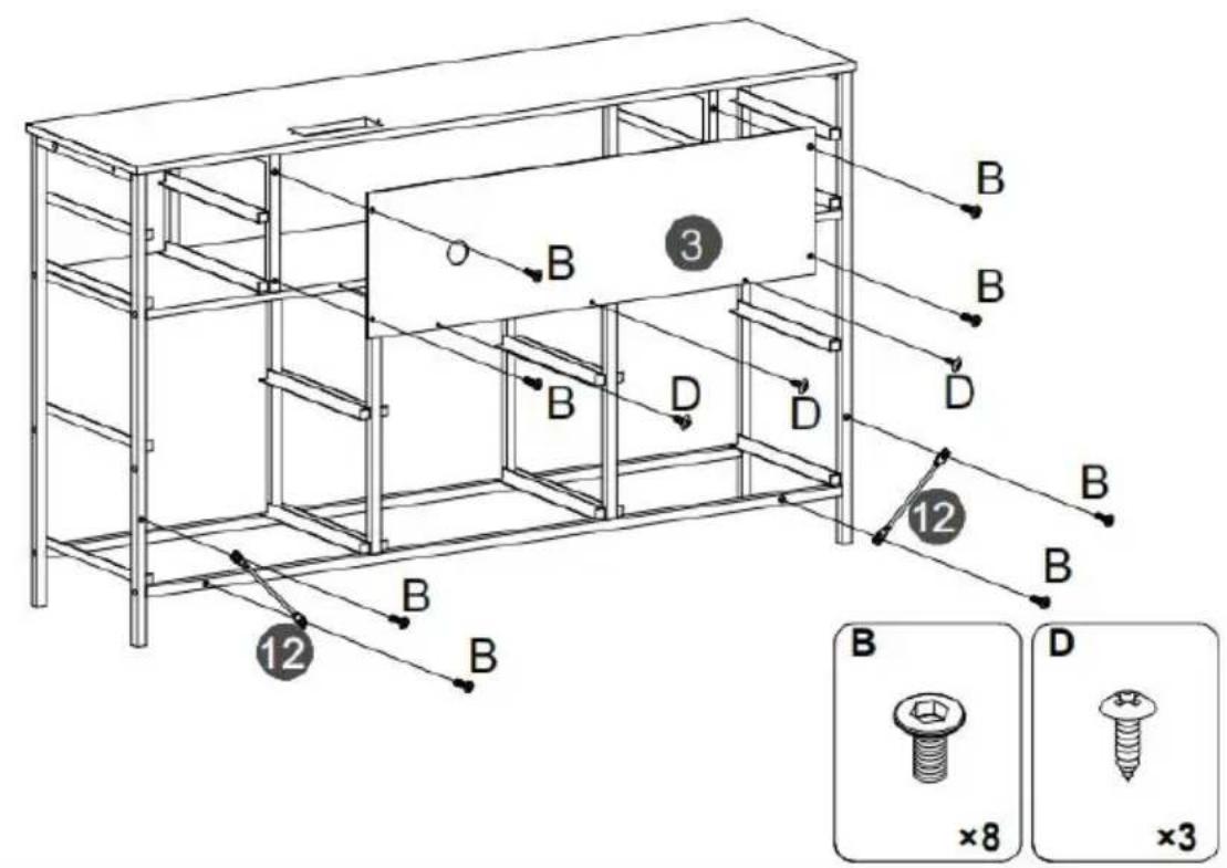
text_image
Technical diagram of a multi-level storage unit with labeled components and assembly details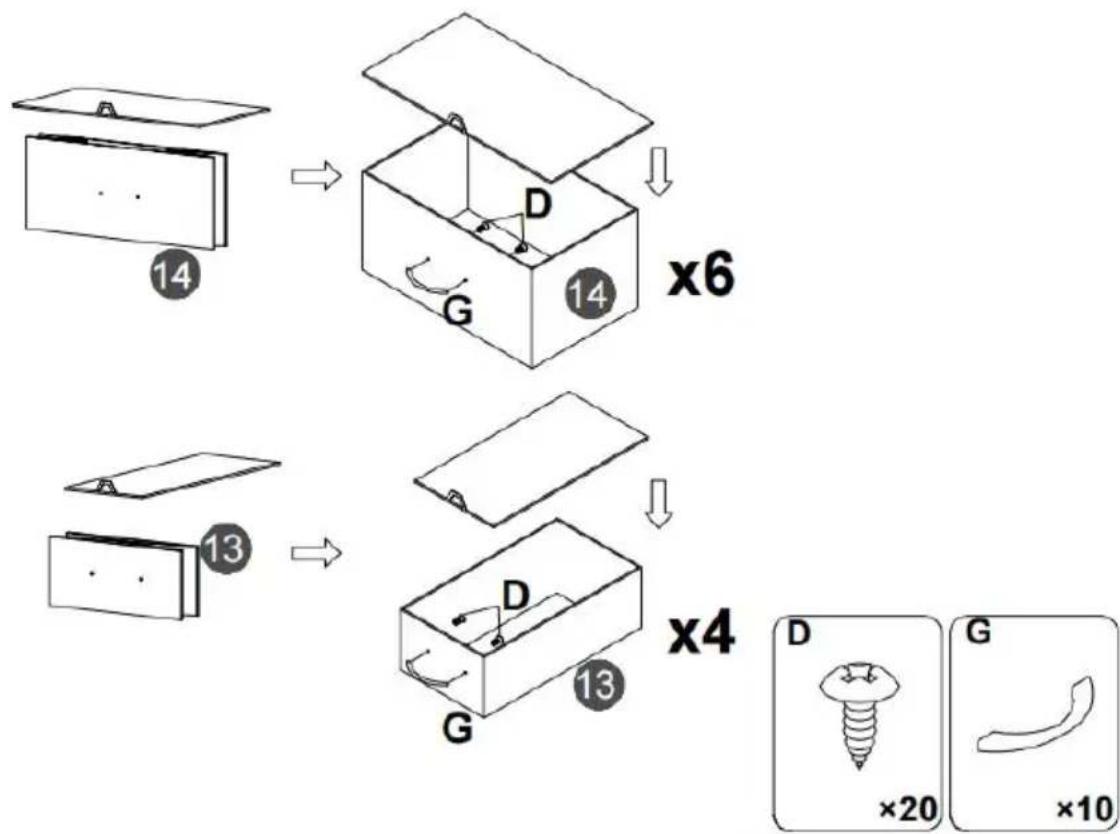
text_image
14 D G x6 14 13 D G x4 13 D ×20 G ×10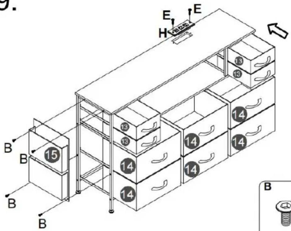
natural_image
Simple diagram of a device with a plug and connector, labeled 'H' and '×1' (no text or symbols on the diagram itself)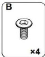
natural_image
Illustration of a bolt with hexagonal nut and cross symbol, labeled 'B' and '×4' (no text or symbols on the bolt itself)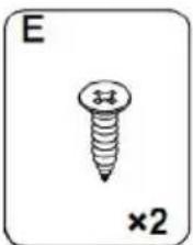
natural_image
Simple line drawing of a screw with a cross mark and '×2' label (no text or symbols on the screw itself)10.
Note:
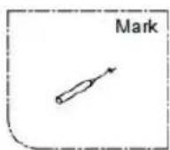
- Mark on the wall
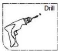
- Use an electric drill to drill deep holes in the wall
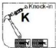
- Tap part K into the hole

After the cabinet assembly, please install the wall xing device on the back of the cabinet to avoid accidents.

Install at a location based on your needs.
text_image
Diagram showing a mechanical setup with labeled components K and a curved component, possibly illustrating a motion or assembly.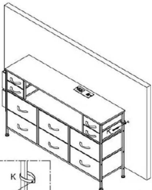
natural_image
Line drawing of a multi-level office cabinet with drawers and storage racks, no text or symbols present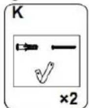
text_image
K ×2Please install anti-tip device as following steps if you need
RGB LED REMOTE CONTROLLER
Anaheim Place, Rancho Cucamonga, CA 91730
| EC | REP |
E-CrossStu GmbH
Mainzer Landstr.69, 60329 Frankfurt am Main
| UK | REP |
YH CONSULTING LIMITED.
C/O YH Consulting Limited Office 147, Centurion House, London Road, Staines-upon-Thames, Surrey TW18 4AX
VEVOR®
TOUGH TOOLS, HALF PRICE
www.vevor.com/support
VEVOR®
TOUGH TOOLS, HALF PRICE
Technisch Ondersteuning en E-garantiecertificaat www.vevor.com/support
LADEKAST VAN STOF
natural_image
Line drawing of a multi-level office drawer cabinet with drawers and handlebars (no text or symbols)HULP NODIG? NEEM CONTACT MET ONS OP!
www.vevor.com/support
- Because plates and screws are not common, please read the manual carefully before installation, and distinguish each plate and screws.
- Please do not tighten the screws too tightly before installation, and tighten all screws after installation.
text_image
Technical diagram showing 12 labeled components of a folding or folding assembly, including horizontal and vertical metal frames.PARTS LIST
text_image
6 7 Back F F F F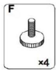
natural_image
Simple line drawing of a screw-like mechanical component (no text or symbols)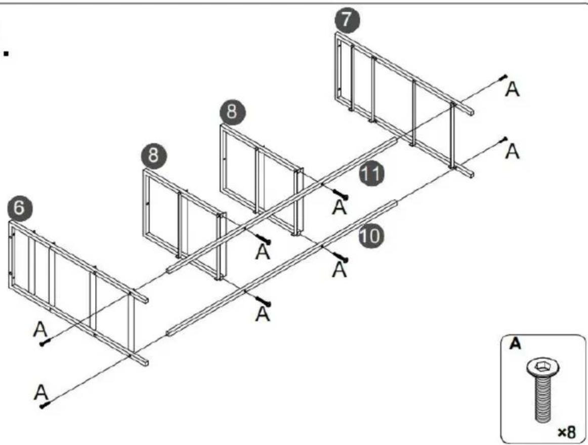
text_image
7 8 11 6 8 10 A A A A A A A A ×8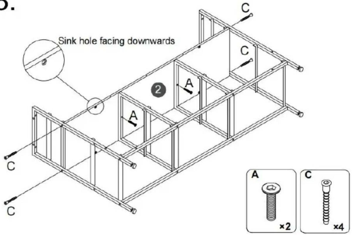
text_image
Sink hole facing downwards A C C 2 A C A ×2 ×4 C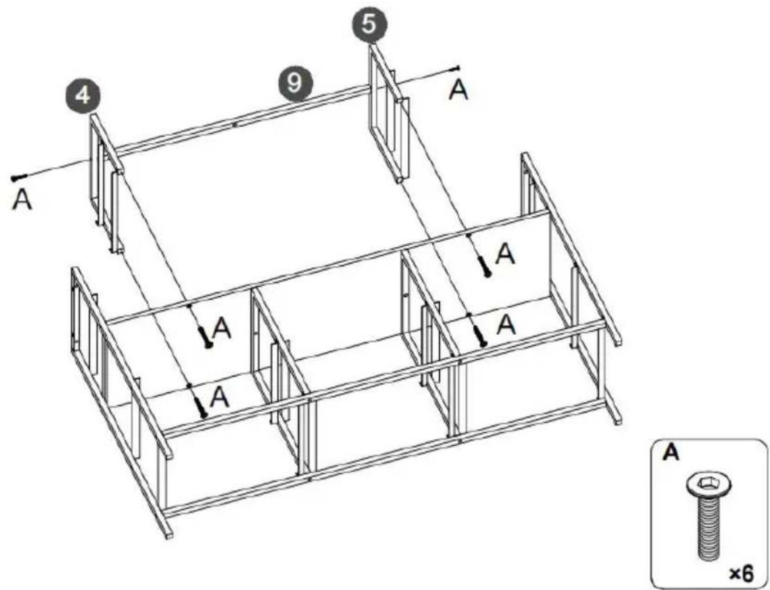
text_image
4 9 5 A A A A A A ×65.
text_image
Step 1. LED J Step 2. LED JFirst, Tear off the back adhesive of the the light strip K, and then stick the light strip J to the back of the top plate 1.
⚠️ Special remind: Remote control without battery.
text_image
al remind: control without battery. J 1 J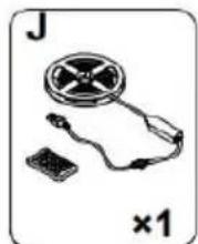
natural_image
Illustration of a handheld electronic device with a circular component and a small rectangular base, labeled 'J' and '×1' (no text or symbols on the device itself)6.
text_image
1 A A A A A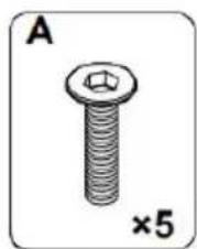
natural_image
Illustration of a bolt with a hexagonal nut, labeled 'A' and '×5' (no text or symbols on the bolt itself)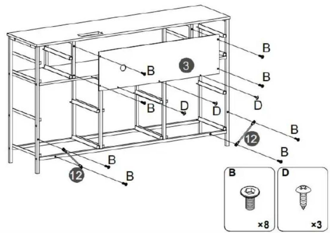
text_image
Technical diagram of a multi-level storage unit with labeled components and assembly details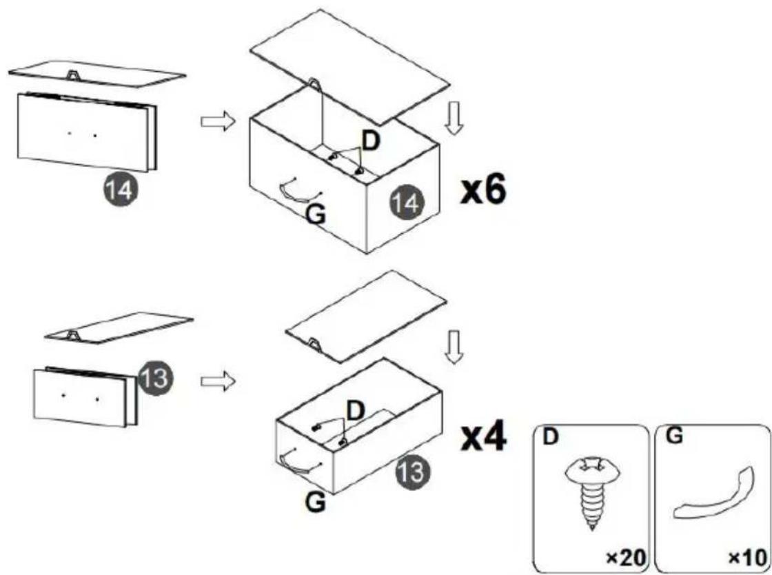
flowchart
graph TD
    A["14"] --> B["14"]
    B --> C["x6"]
    D["13"] --> E["13"]
    E --> F["x4"]
    G["D"] --> H["G"]
    H --> I["×20"]
    J["G"] --> K["×10"]
natural_image
Simple diagram of a plug with a terminal block and connector, labeled 'H' and '×1' (no text or symbols on the diagram itself)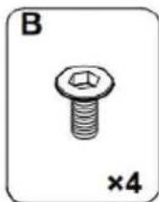
natural_image
Illustration of a hexagonal bolt with a nut, labeled 'B' and '×4' (no text or symbols on the bolt itself)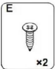
natural_image
Simple line drawing of a screw with a cross mark and '×2' label (no text or symbols on the screw itself)10.
Note:
- Mark on the wall
- Use an electric drill to drill deep holes in the wall
- Tap part K into the hole

After the cabinet assembly, please install the wall xing device on the back of the cabinet to avoid accidents.

Install at a location based on your needs.
text_image
Diagram showing a mechanical setup with labeled components K and a curved component, possibly illustrating a motion or assembly.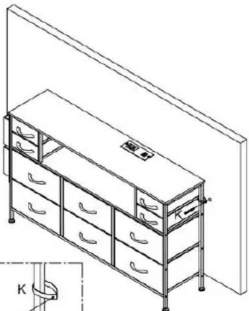
natural_image
Line drawing of a multi-level office cabinet with drawers and storage racks, no text or symbols present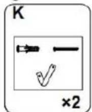
text_image
K ×2Please install anti-tip device as following steps if you need
RGB LED REMOTE CONTROLLER
Anaheim Place, Rancho Cucamonga, CA 91730
| EC | REP |
E-CrossStu GmbH
Mainzer Landstr.69, 60329 Frankfurt am Main
| UK | REP |
YH CONSULTING LIMITED.
C/O YH Consulting Limited Office 147, Centurion House, London Road, Staines-upon-Thames, Surrey TW18 4AX
VEVOR®
TOUGH TOOLS, HALF PRICE
www.vevor.com/support
VEVOR®
TOUGH TOOLS, HALF PRICE
natural_image
Line drawing of a multi-level office drawer cabinet with drawers and handlebars (no text or symbols)BEHÖVER HJÄLP? KONTAKTA OSS!
- Because plates and screws are not common, please read the manual carefully before installation, and distinguish each plate and screws.
- Please do not tighten the screws too tightly before installation, and tighten all screws after installation.

text_image
Technical diagram showing 12 labeled components of a folding or folding assembly, including horizontal and vertical metal frames.PARTS LIST
text_image
6 7 Back F F F F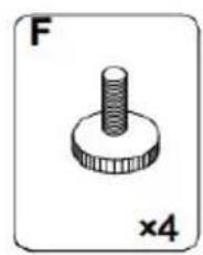
natural_image
Simple line drawing of a screw-like mechanical component (no text or symbols)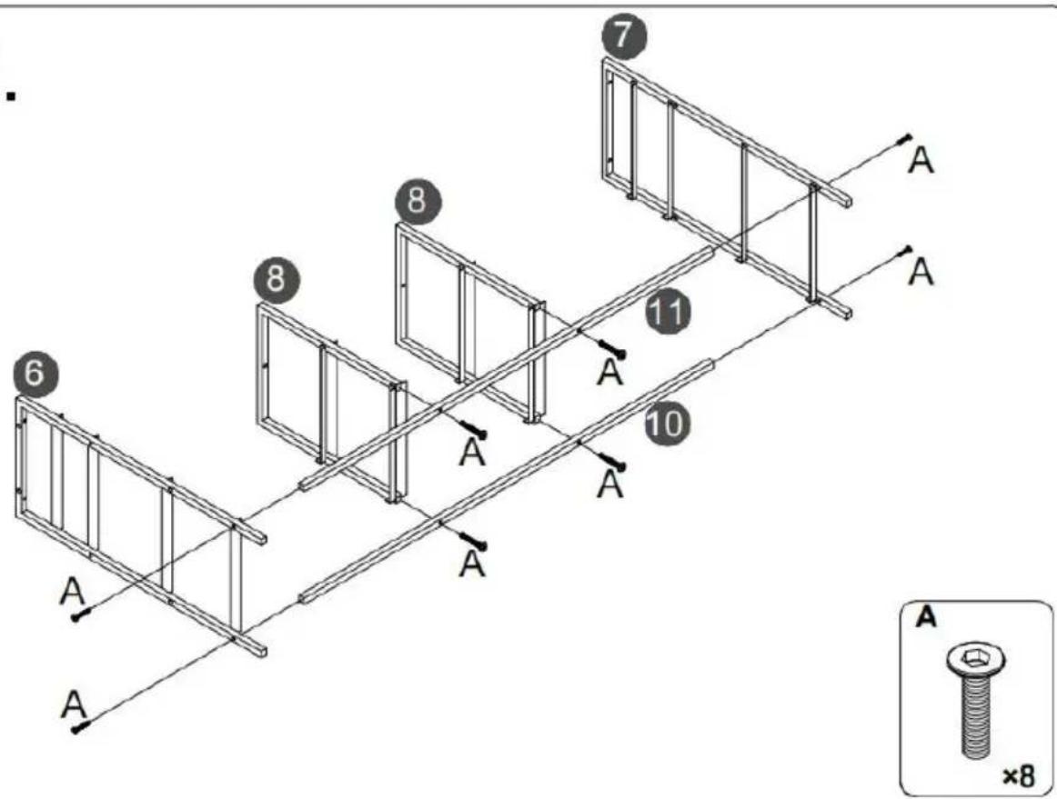
text_image
7 8 11 6 8 10 A A A A A A A A A ×8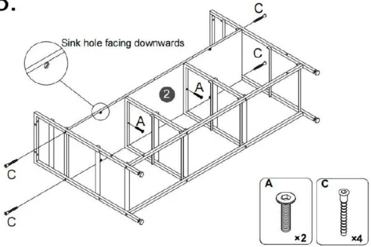
text_image
Sink hole facing downwards A C C 2 A C A ×2 ×4 C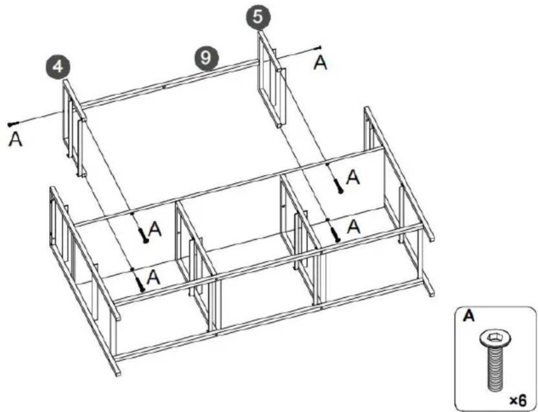
text_image
4 9 5 A A A A A A ×65.
text_image
Step 1. LED J Step 2. LED JFirst, Tear off the back adhesive of the the light strip K, and then stick the light strip J to the back of the top plate 1.
⚠️ Special remind: Remote control without battery.
text_image
al remind: control without battery. J 1 J
natural_image
Illustration of a handheld electronic device with a circular component and a small rectangular base, labeled 'J' and '×1' (no text or symbols on the device itself)6.
text_image
1 A A A A A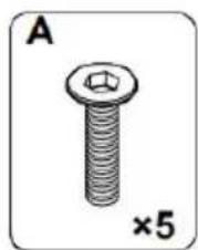
natural_image
Illustration of a bolt with a hexagonal nut, labeled 'A' and '×5' (no text or symbols on the bolt itself)
text_image
Technical diagram of a multi-level storage unit with labeled components and assembly details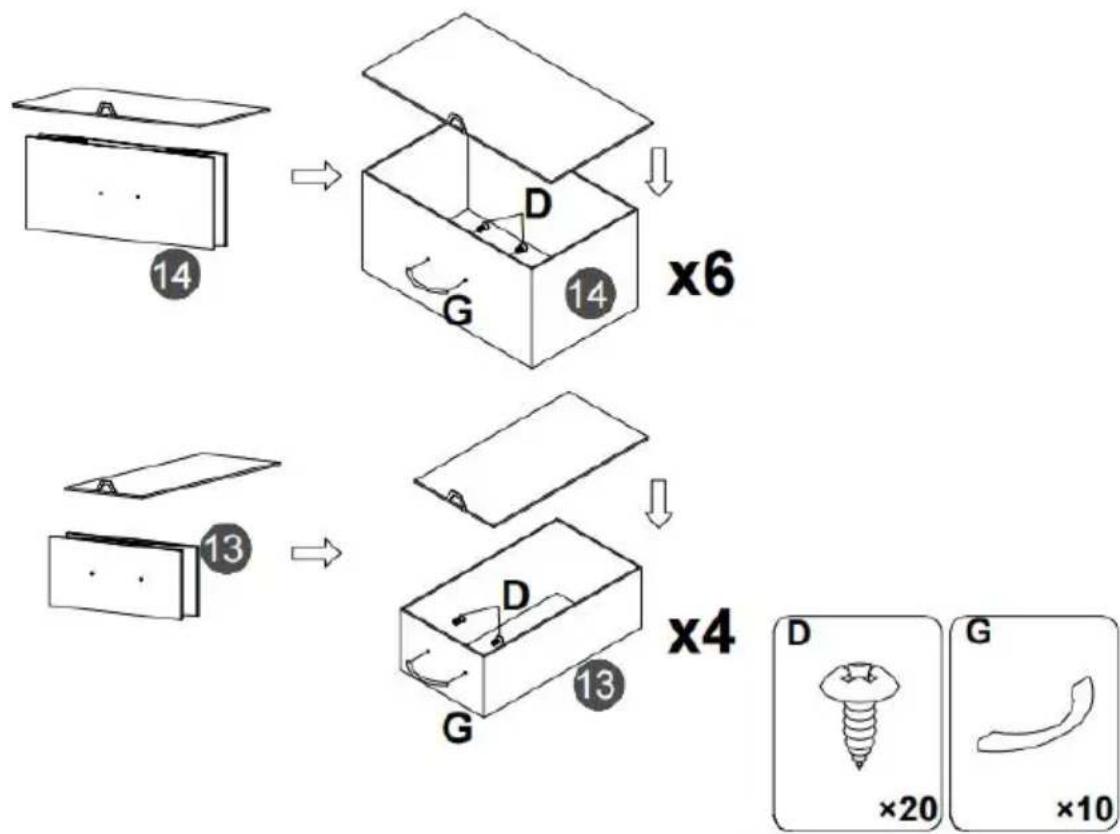
flowchart
graph TD
    A["14"] --> B["14"]
    B --> C["×6"]
    D["13"] --> E["13"]
    E --> F["×4"]
    G["D"] --> H["G"]
    I["D"] --> J["G"]
    K["D"] --> L["G"]
    M["×20"] --> N["×10"]
natural_image
Simple diagram of a plug with a terminal block and connector, labeled 'H' and '×1' (no text or symbols on the diagram itself)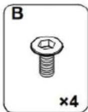
natural_image
Illustration of a hexagonal bolt with a nut, labeled 'B' and '×4' (no text or symbols on the bolt itself)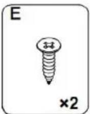
natural_image
Simple line drawing of a screw with a cross mark and '×2' label (no text or symbols on the screw itself)10.
Note:
- Mark on the wall
- Use an electric drill to drill deep holes in the wall
- Tap part K into the hole
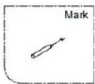

After the cabinet assembly, please install the wall xing device on the back of the cabinet to avoid accidents.
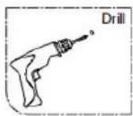

Install at a location based on your needs.
text_image
Diagram showing a mechanical setup with labeled components K and a curved component, likely illustrating a motion or assembly.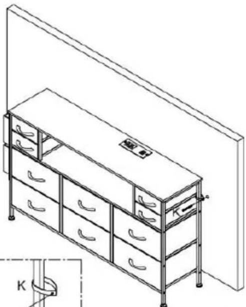
natural_image
Line drawing of a multi-level office cabinet with drawers and storage racks, no text or symbols present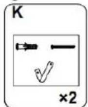
text_image
K ×2Please install anti-tip device as following steps if you need
RGB LED REMOTE CONTROLLER
text_image
1 2 3 4 5 MODE + SPEED - DEMO . SPEED + COLOR . M O D E B R I G T . B R I G T . COLOR . B R I G T . RF Wireless1. Slå på/standby
C/O YH Consulting Limited Office 147, Centurion House, London Road, Staines-upon-Thames, Surrey TW18 4AX
VEVOR®
TOUGH TOOLS, HALF PRICE
www.vevor.com/support
VEVOR®
TOUGH TOOLS, HALF PRICE
natural_image
Line drawing of a multi-level office drawer cabinet with drawers and handlebars (no text or symbols)- Because plates and screws are not common, please read the manual carefully before installation, and distinguish each plate and screws.
- Please do not tighten the screws too tightly before installation, and tighten all screws after installation.
text_image
Technical diagram showing 12 numbered components of a folding or folding assembly, including horizontal and vertical metal frames.PARTS LIST
text_image
6 7 Back F F F F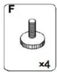
natural_image
Simple line drawing of a screw-like mechanical component (no text or symbols)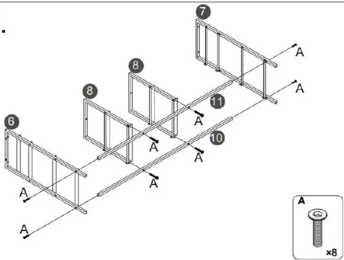
text_image
7 8 11 6 8 10 A A A A A A A A A ×8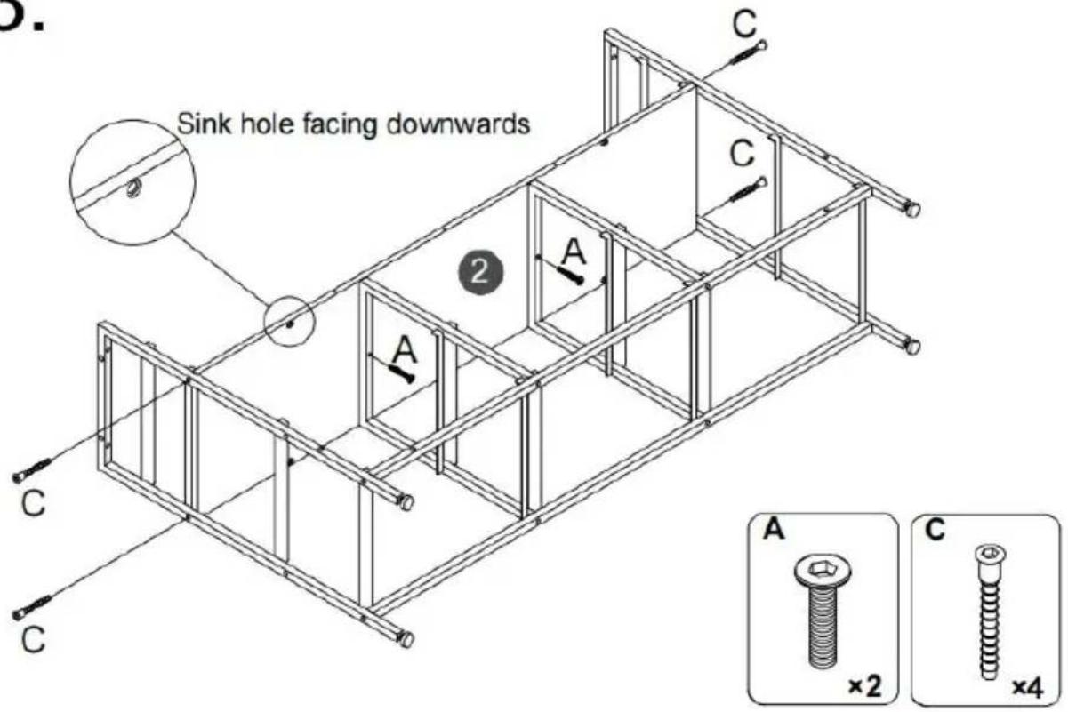
text_image
Sink hole facing downwards A C C 2 A C A ×2 ×4 C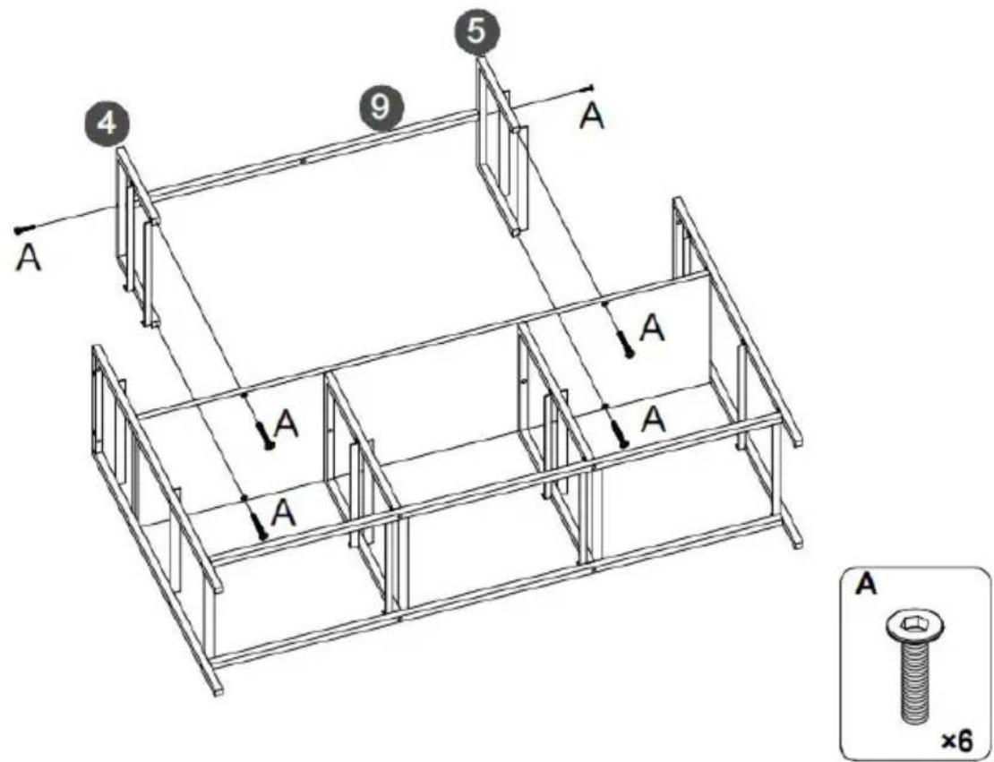
text_image
4 9 5 A A A A A A ×65.
text_image
Step 1. LED J Step 2. LED JFirst, Tear off the back adhesive of the the light strip K, and then stick the light strip J to the back of the top plate 1.
⚠️ Special remind: Remote control without battery.
text_image
al remind: control without battery. J 1 J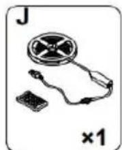
natural_image
Illustration of a handheld electronic device with a circular component and a small rectangular base, labeled 'J' and '×1' (no text or symbols on the device itself)6.
text_image
1 A A A A A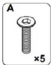
natural_image
Illustration of a bolt with a hexagonal nut, labeled 'A' and '×5' (no text or symbols on the bolt itself)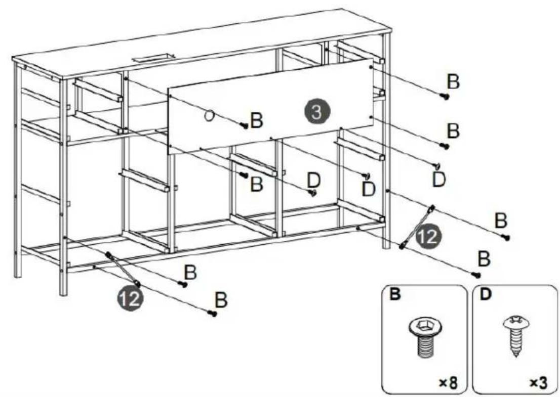
text_image
14 D G x6 14 13 D G x4 13 D ×20 G ×10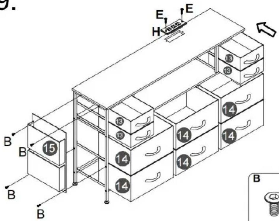
natural_image
Simple diagram of a device with a plug and connector, labeled 'H' and '×1' (no text or symbols on the diagram itself)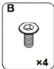
natural_image
Illustration of a bolt with hexagonal nut and cross symbol, labeled 'B' and '×4' (no text or symbols on the bolt itself)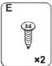
natural_image
Simple line drawing of a screw with a cross mark and '×2' label (no text or symbols on the screw itself)10.
Note:
- Mark on the wall
- Use an electric drill to drill deep holes in the wall
- Tap part K into the hole

After the cabinet assembly, please install the wall xing device on the back of the cabinet to avoid accidents.

Install at a location based on your needs.
text_image
Diagram showing a mechanical setup with labeled components K and a curved component, possibly illustrating a motion or assembly.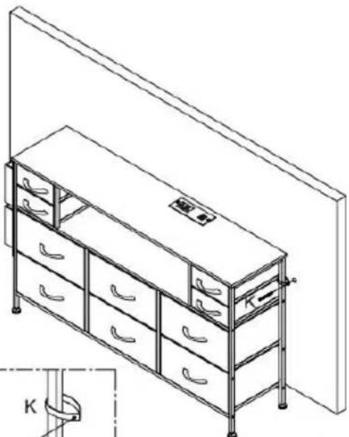
natural_image
Line drawing of a multi-level office cabinet with drawers and storage racks, no text or symbols present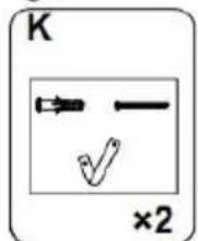
text_image
K ×2Please install anti-tip device as following steps if you need
RGB LED REMOTE CONTROLLER
C/O YH Consulting Limited Office 147, Centurion House, London Road, Staines-upon-Thames, Surrey TW18 4AX
VEVOR®
TOUGH TOOLS, HALF PRICE
natural_image
Line drawing of a multi-level office drawer cabinet with drawers and handlebars (no text or symbols)- Because plates and screws are not common, please read the manual carefully before installation, and distinguish each plate and screws.
- Please do not tighten the screws too tightly before installation, and tighten all screws after installation.
text_image
Technical diagram showing 12 numbered components of a folding or folding assembly, including horizontal and vertical metal frames.PARTS LIST
text_image
6 7 Back F F F F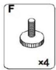
natural_image
Simple line drawing of a screw-like mechanical component (no text or symbols)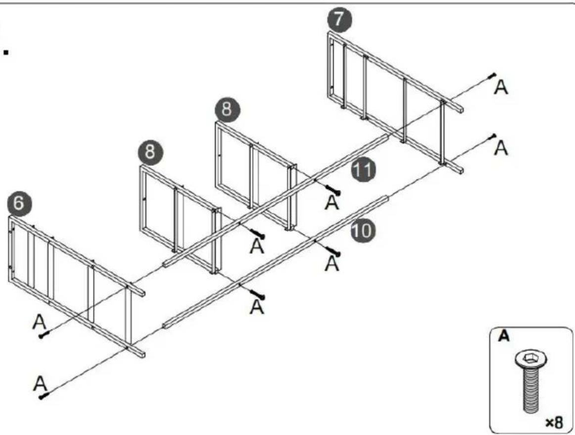
text_image
7 8 11 6 8 10 A A A A A A A A A ×8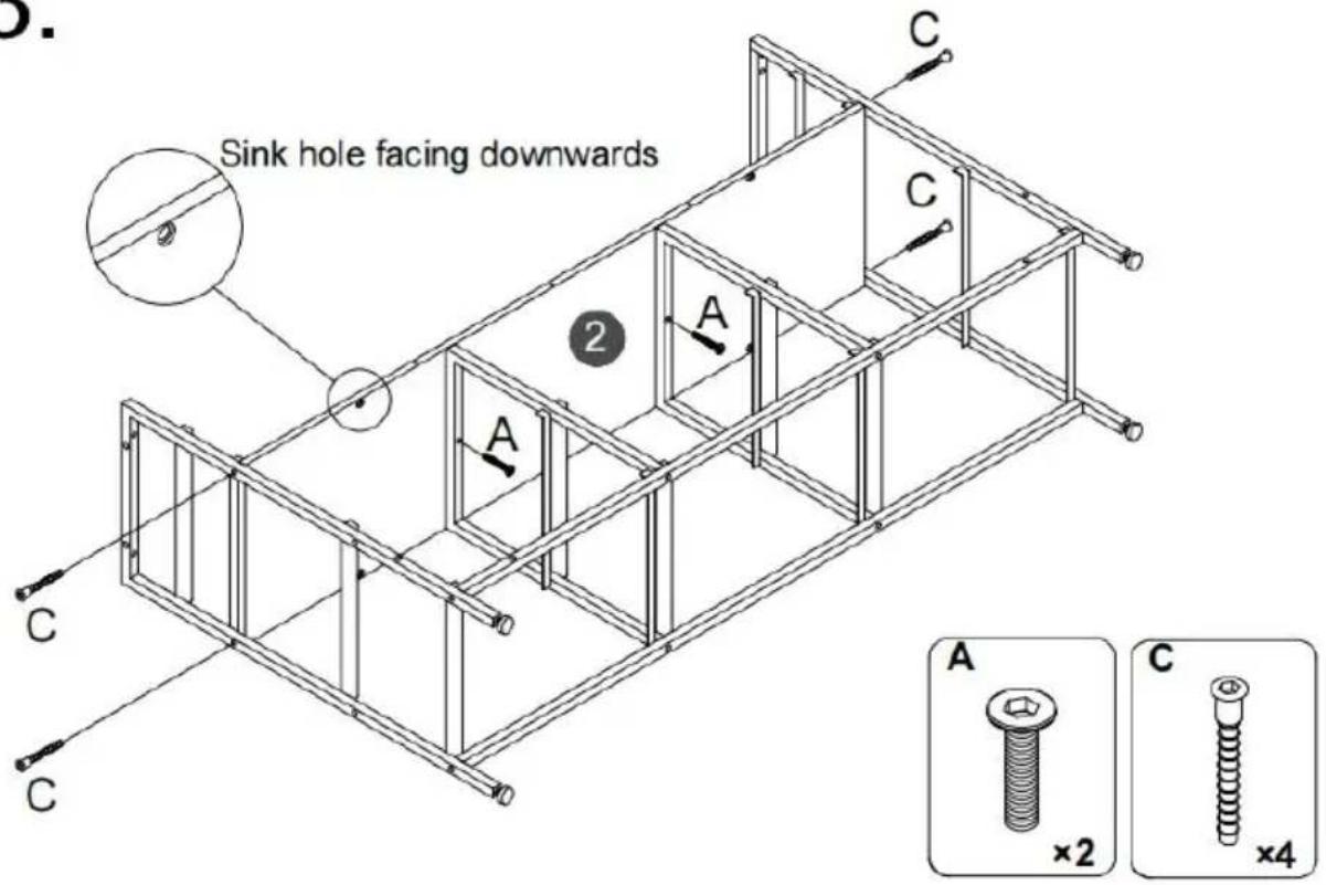
text_image
Sink hole facing downwards A C C 2 A C A ×2 ×4 C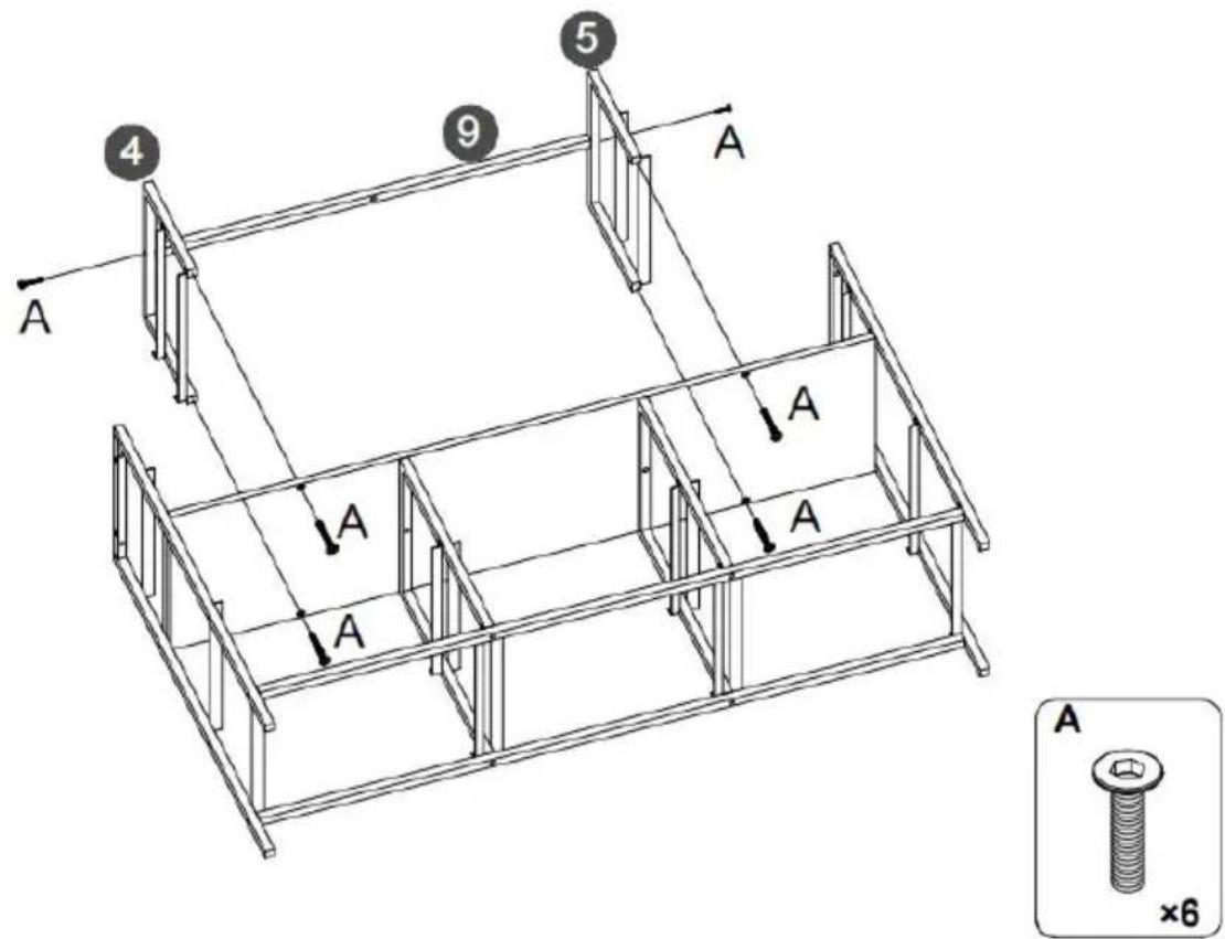
text_image
4 9 5 A A A A A A ×65.
text_image
Step 1. LED J Step 2. LED JFirst, Tear off the back adhesive of the the light strip K, and then stick the light strip J to the back of the top plate 1.
⚠️ Special remind: Remote control without battery.
text_image
al remind: control without battery. J 1 J
natural_image
Illustration of a handheld electronic device with a circular component and a small rectangular base, labeled 'J' and '×1' (no text or symbols on the device itself)6.
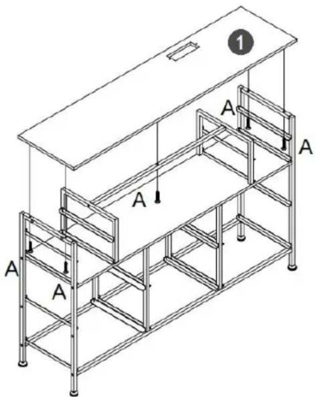
text_image
1 A A A A A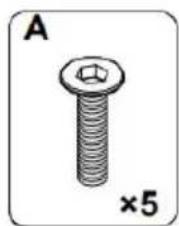
natural_image
Illustration of a bolt with a hexagonal head and threaded shaft, labeled 'A' and '×5' (no text or symbols on the object itself)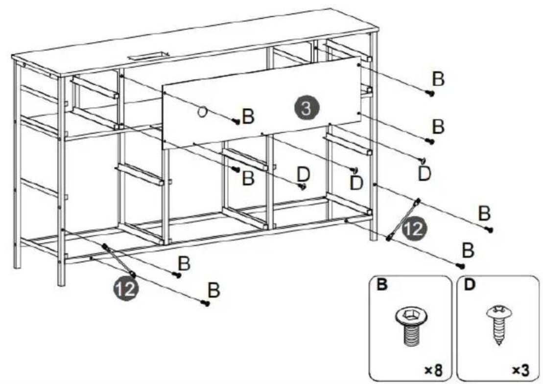
text_image
Technical diagram of a multi-level storage unit with labeled components and assembly details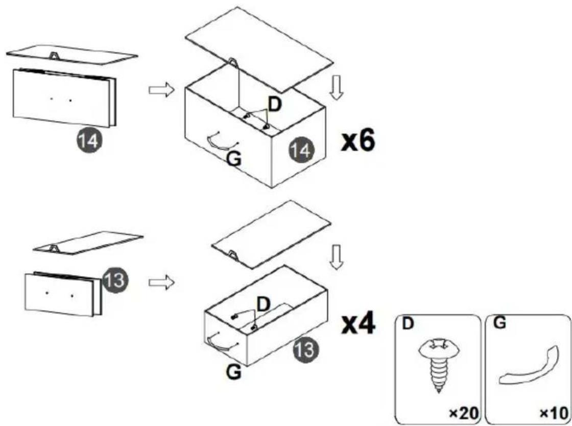
flowchart
graph TD
    A["14"] --> B["14"]
    B --> C["x6"]
    D["13"] --> E["13"]
    E --> F["x4"]
    G["D"] --> H["G"]
    H --> I["×20"]
    J["G"] --> K["×10"]
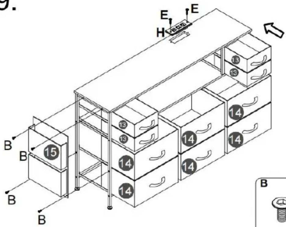
text_image
9. E H E 13 13 14 14 14 15 13 13 14 14 14 B B B B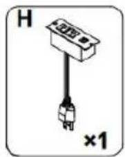
natural_image
Simple diagram of a plug with a terminal block and connector, labeled 'H' and '×1' (no text or symbols on the diagram itself)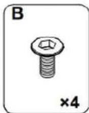
natural_image
Illustration of a hexagonal bolt with a nut, labeled 'B' and '×4' (no text or symbols on the bolt itself)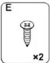
natural_image
Simple line drawing of a screw with a cross mark and '×2' label (no text or symbols on the screw itself)10.
Note:
- Mark on the wall
- Use an electric drill to drill deep holes in the wall
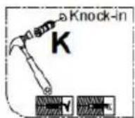
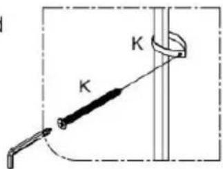
- Tap part K into the hole
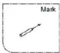

After the cabinet assembly, please install the wall xing device on the back of the cabinet to avoid accidents.
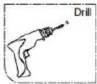

Install at a location based on your needs.
text_image
Diagram showing a mechanical setup with labeled components K and a curved component, likely illustrating a motion or assembly.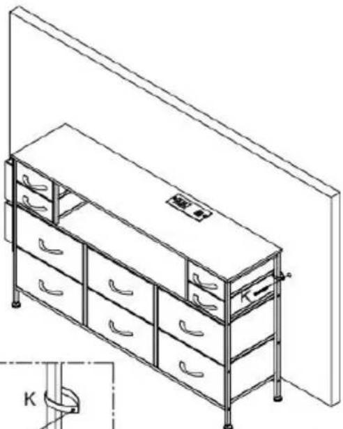
natural_image
Line drawing of a multi-level office cabinet with drawers and storage racks, no text or symbols present
text_image
K ×2Please install anti-tip device as following steps if you need
RGB LED REMOTE CONTROLLER
Importato in AUS: SIHAO PTY LTD. 1 ROKEVA STREETEASTWOOD NSW 2122 Australia
Importato negli USA: Sanven Technology Ltd. Suite 250, 9166 Anaheim Place, Rancho Cucamonga, CA 91730
| EC | REP |
E-CrossStu GmbH
Mainzer Landstr.69, 60329 Frankfurt am Main
| UK | REP |
YH CONSULTING LIMITED.
C/O YH Consulting Limited Office 147, Centurion House, London Road, Staines-upon-Thames, Surrey TW18 4AX
VEVOR®
TOUGH TOOLS, HALF PRICE