J10030-68-FB - Wardrobe Vevor - Free user manual and instructions
Find the device manual for free J10030-68-FB Vevor in PDF.

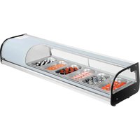
| Product type | Triangular corner cabinet |
| Brand | Vevor |
| Model | J10030-68-FB |
| Dimensions (W x D x H) | 685 x 360 x 1710 mm |
| Net weight | Approximately 33 kg |
| Material | Steel |
| Color | Black |
| Main functions | Storage, use in corners |
| Number of shelves | 4 |
| Load capacity per shelf | 20 kg |
| Assembly required | Yes, follow the instructions provided |
| Safety precautions | Do not let children play nearby, use on a flat and hard surface, do not exceed weight capacity, inspect before each use |
| Maintenance and cleaning | Clean with a damp cloth and a mild detergent. Avoid abrasive products. |
| Spare parts and repairability | Contact support via www.vevor.com/support |
| Warranty | Electronic warranty certificate available at www.vevor.com/support |
| General information | User manual available in PDF format. Multiple languages. |
Frequently Asked Questions - J10030-68-FB Vevor
User questions about J10030-68-FB Vevor
0 question about this device. Answer the ones you know or ask your own.
Ask a new question about this device
Download the instructions for your Wardrobe in PDF format for free! Find your manual J10030-68-FB - Vevor and take your electronic device back in hand. On this page are published all the documents necessary for the use of your device. J10030-68-FB by Vevor.
USER MANUAL J10030-68-FB Vevor
Technical Support and E-Warranty Certificate www.vevor.com/support
TRIANGLE CORNER CABINET USER MANUAL
MODEL NO.: J10030-68-FB
We continue to be committed to provide you tools with competitive price. "Save Half", "Half Price" or any other similar expressions used by us only represents an estimate of savings you might benefit from buying certain tools with us compared to the major top brands and does not necessarily mean to co all categories of tools offered by us. You are kindly reminded to verify carefully when you are placing an order with us if you are actually Saving Half in comparison with the top major brands.
VEVOR®
TOUGH TOOLS, HALF PRICE
Triangle Corner Cabinet
MODEL NO.: J10030-68-FB

natural_image
Line drawing of a multi-tiered cabinet or enclosure structure with no text or symbolsNEED HELP? CONTACT US!
Have product questions? Need technical support? Please feel free to contact us:
Technical Support and E-Warranty Certificate www.vevor.com/support
This is the original instruction, please read all manual instructions carefully before operating. VEVOR reserves a clear interpretation of o user manual. The appearance of the product shall be subject to the product you received. Please forgive us that we won't inform you ag there are any technology or software updates on our product.

WARNING:
Please read this manual carefully before using the product. Failure do so may result in serious injury.

Please read and observe carefully all the assembly instructions before beginning assembly.

Unit should be assembled by two or more people.

Please do not let your child climb on the product. If y kids or animals who like to climb, we highly recommend using the wall anchors and brackets/straps that come the package.
ASSEMBLY PRECAUTIONS
-
Assemble only according to these instructions. Improper assembly c create hazards.
-
Wear ANSI-approved safety goggles and heavy-duty work gloves during assembly.
-
Keep the assembly area clean and well-lit.
-
Keep bystanders out of the area during assembly.
-
Do not assemble when tired or when under the influence of alcohol drugs or medication.
-
The product capabilities apply to properly and completely assembled products only.
-
Assemble on a flat, level, hard and smooth surface capable of sa supporting the Triangle Corner Cabinet.
- For additional information regarding the parts listed in the following pages, please refer to the Assembly Diagram of this manual. Unwrap separate all parts in a clean work area.
SAVE THESE INSTRUCTIONS
USE PRECAUTIONS
TO PREVENT SERIOUS INJURY AND DEATH FROM TIPPING:
- This product is not a toy Do not allow children to play with or r item.
- Do not exceed weight capacities, before moving.
- Use only on a flat, hard and smooth surface capable of safely supporting a fully loaded Triangle Corner Cabinet.
- Use as intended only.
Inspect before every use; do not use if parts are loose or damaged.
TECHNICAL SPECIFICATIONS
| Model | J10030-68-FB |
| Product Dimensions (LxWxH)(mm) | 685*360*1710 |
| Net Weight(kg) | About 33 |
*Products such as specifications, appearance, and design are subject to modification without prior notice.
A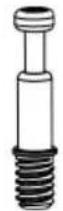 41X+4X 41X+4X | B∅15*12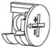 41X+4X 41X+4X | C∅8x30mm 46X+4X 46X+4X | D∅6.3*50mm 12X+1X 12X+1X |
E 4X 4X | F 2X 2X | G 4X 4X | H 4X 4X |
I 41X+4X 41X+4X | J 8X 8X | K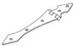 8X 8X | L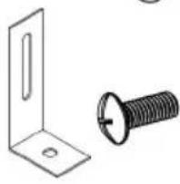 2X 2X |
M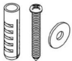 2X 2X | N∅3.5*15mm 28X+2X 28X+2X | O∅5/32"×20mm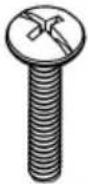 8X 8X | P∅3.5*15mm[8TT]40X+4X |
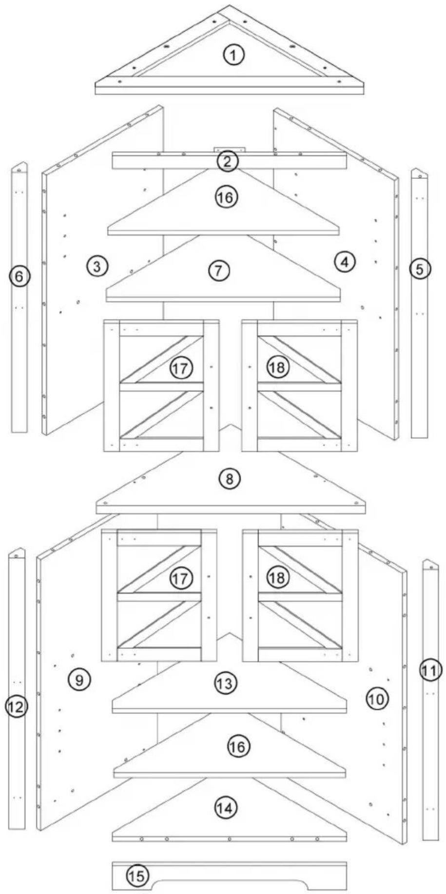
ASSEMBLY STEPS
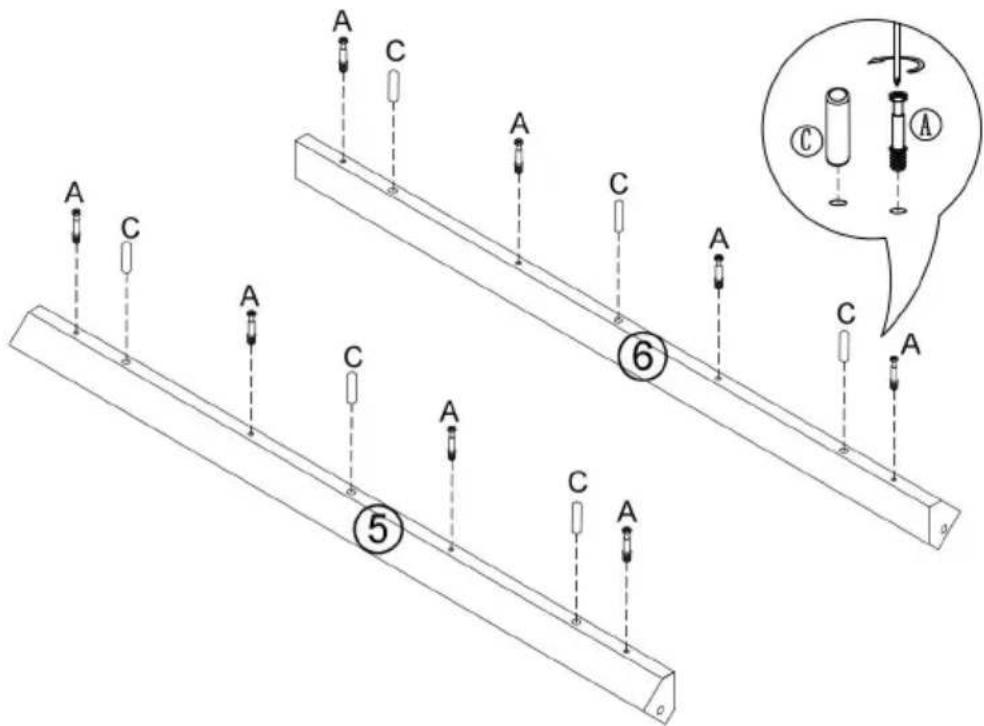
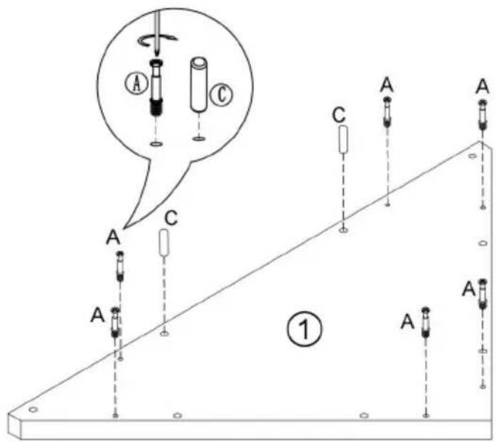
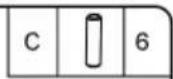
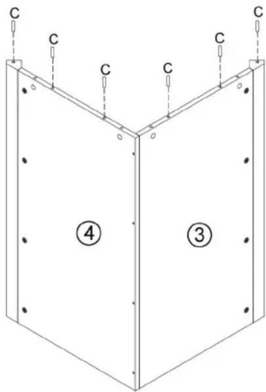
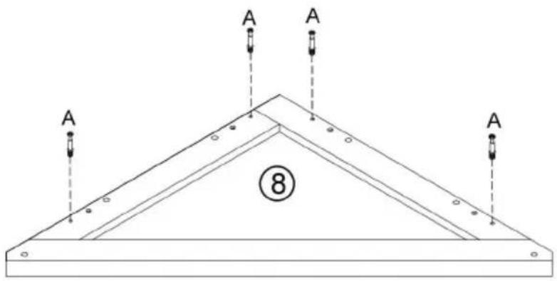
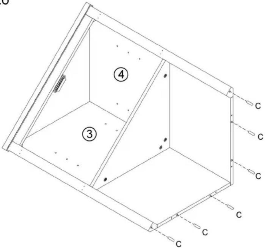
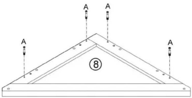
Step 1
| A | 8 | |
| C | 6 |

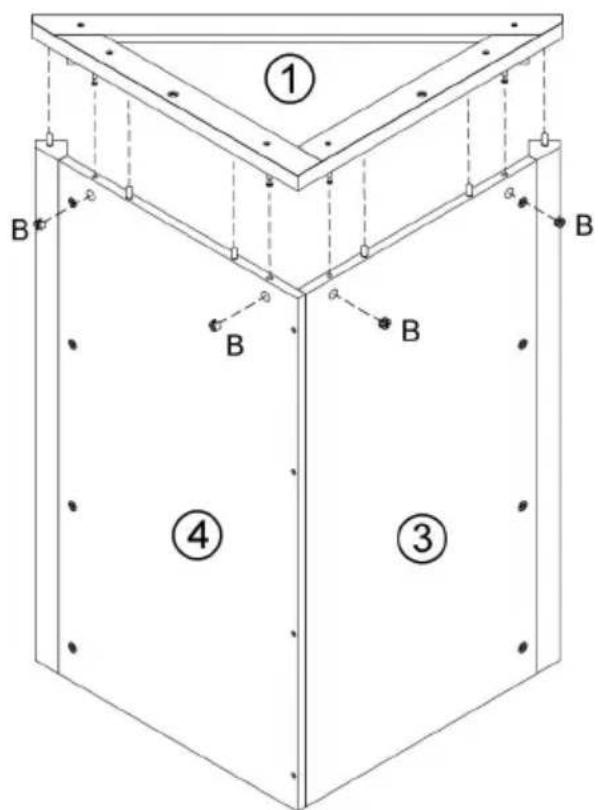
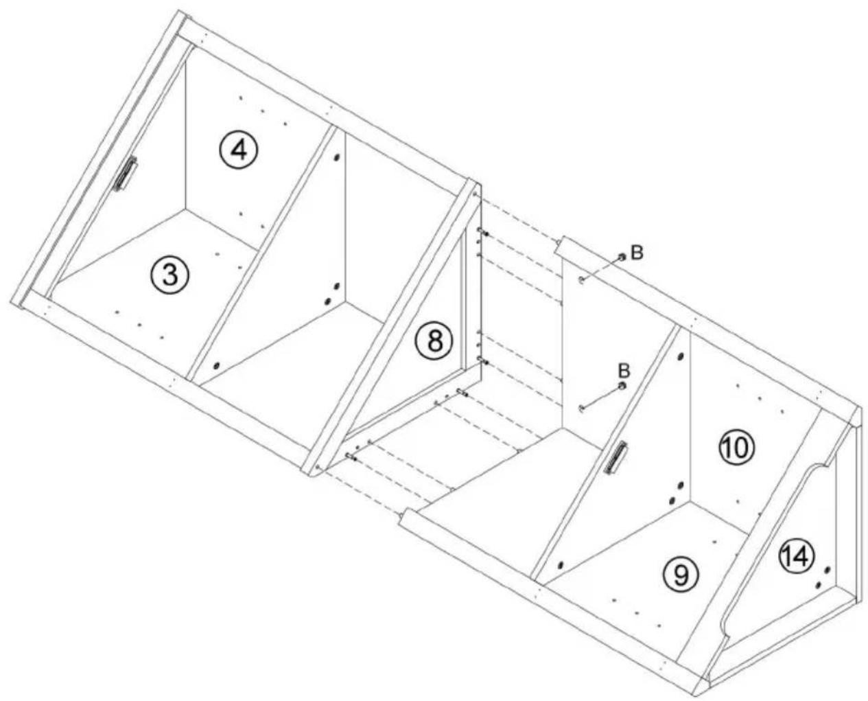
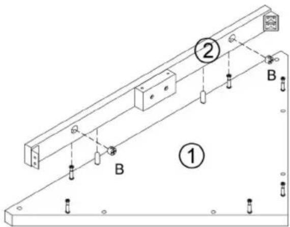
Step 2
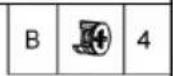
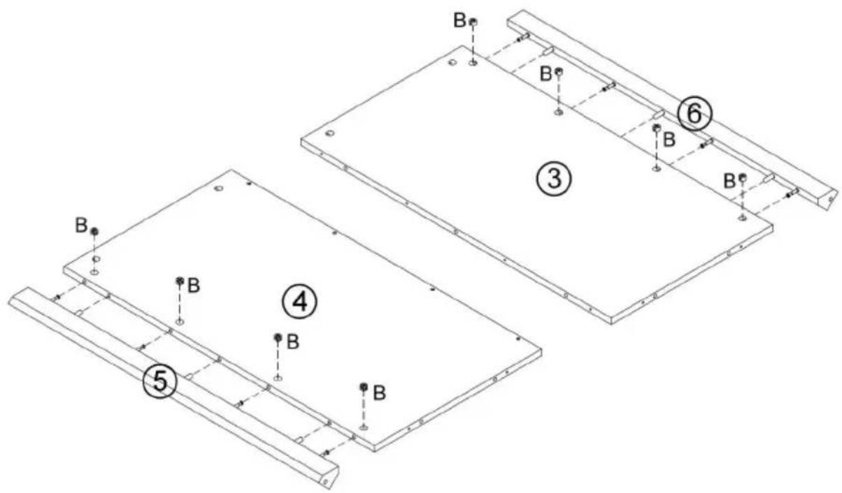
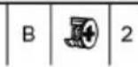
| B | 8 |
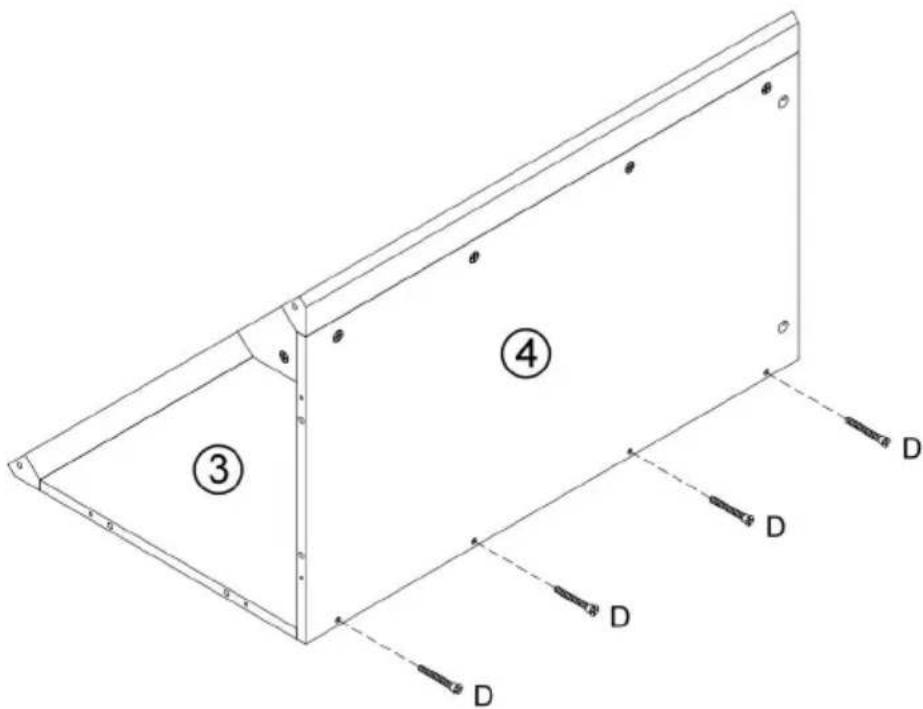
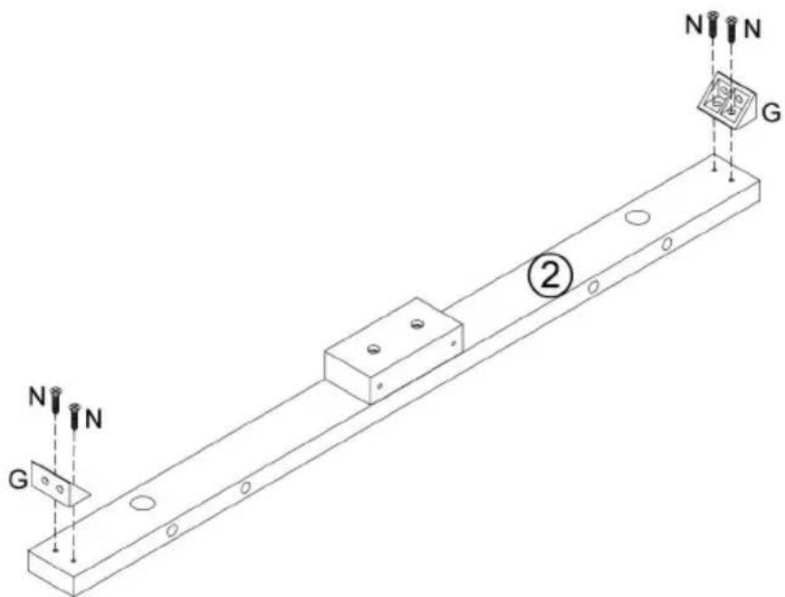
Step 4
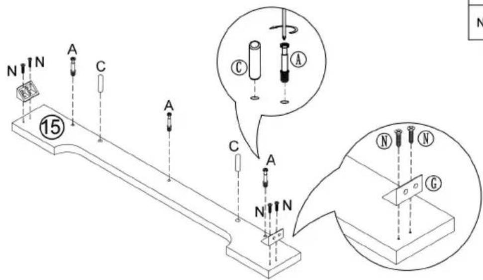
| A | 3 | |
| C | 2 | |
| G | 2 | |
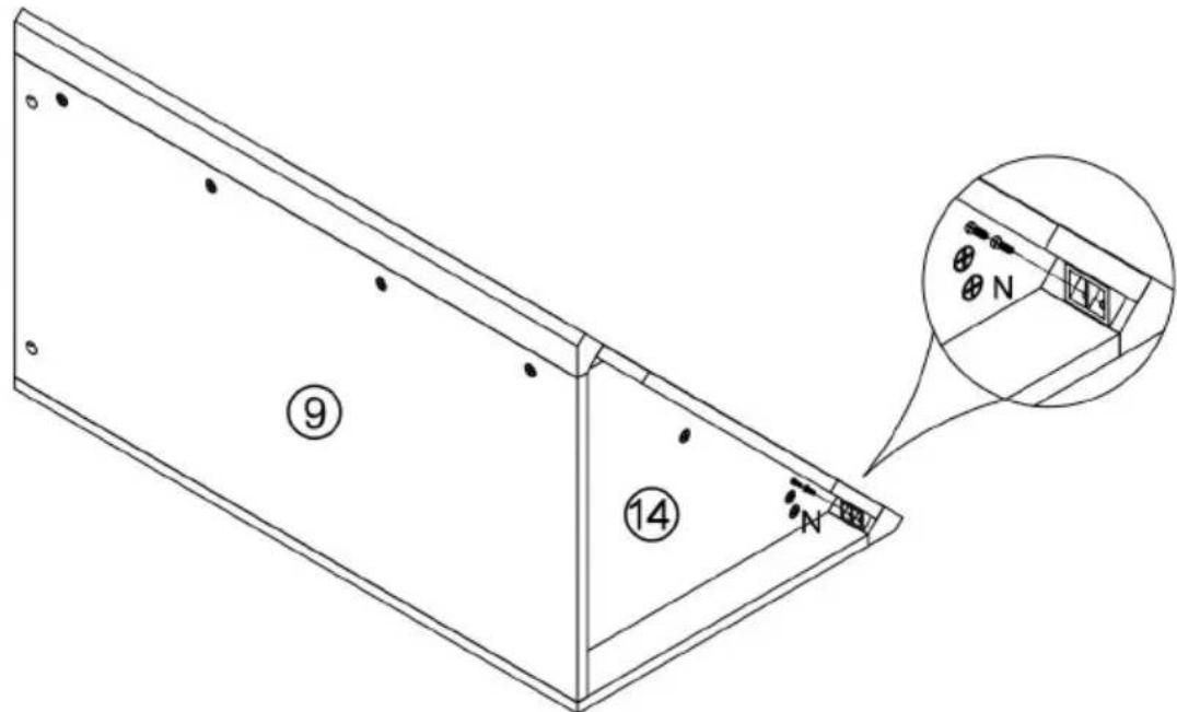
| N | 4 |

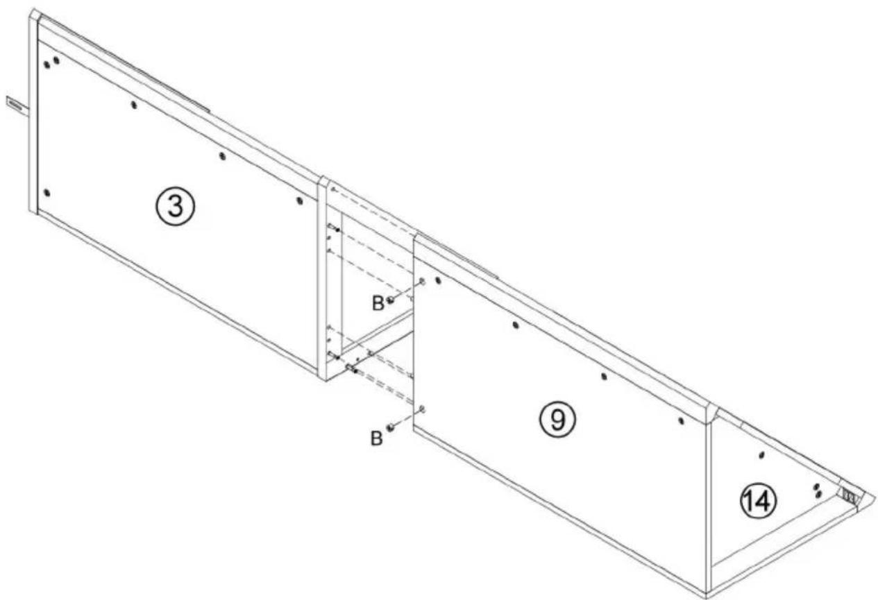
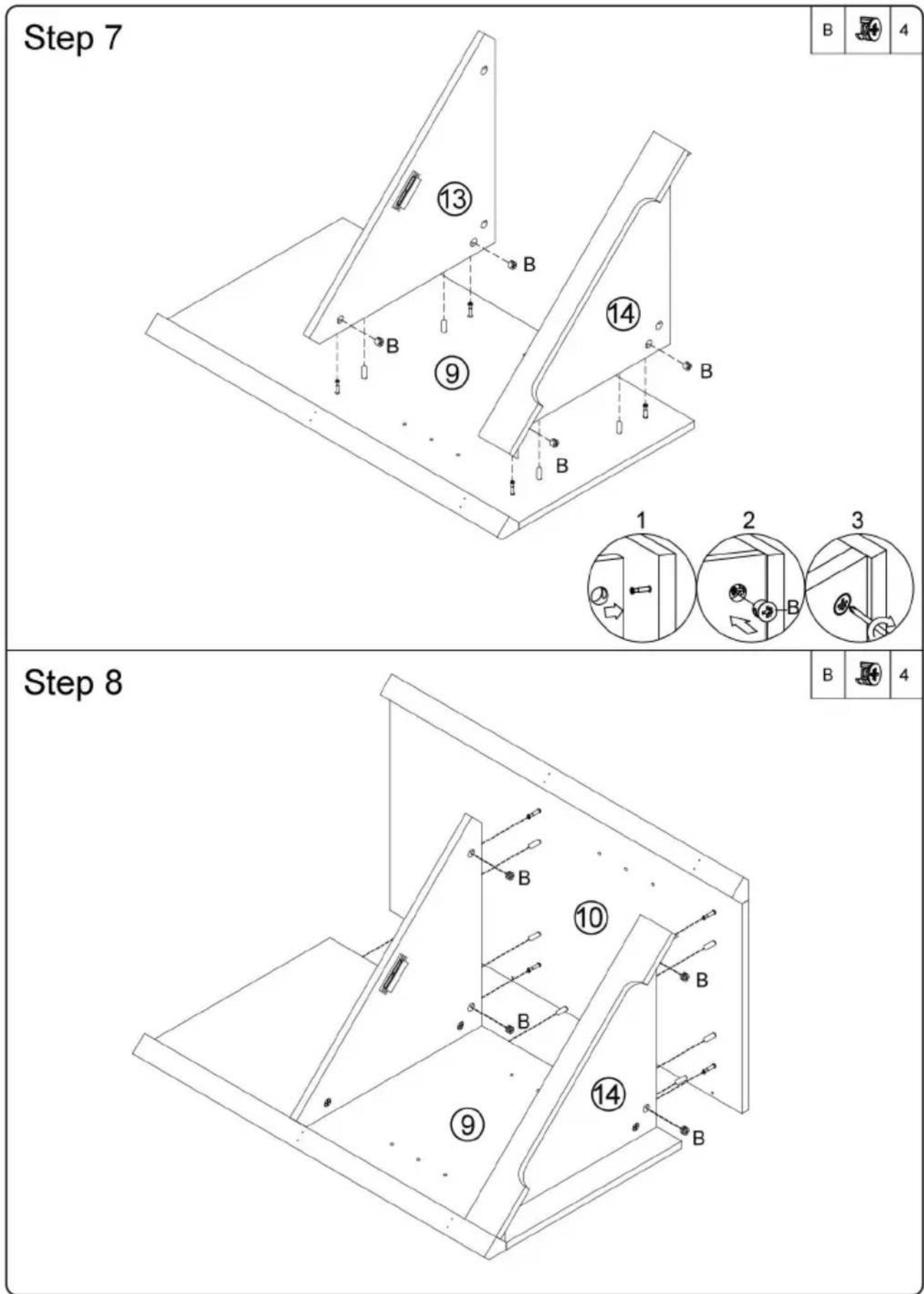
Step 5
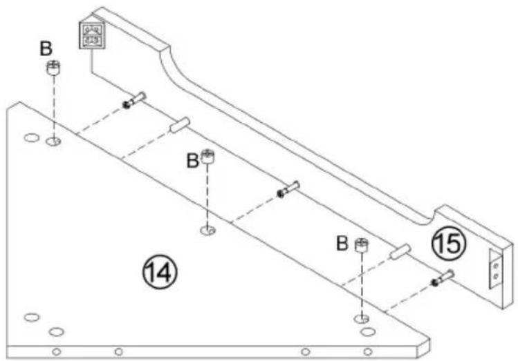
| B | 3 |


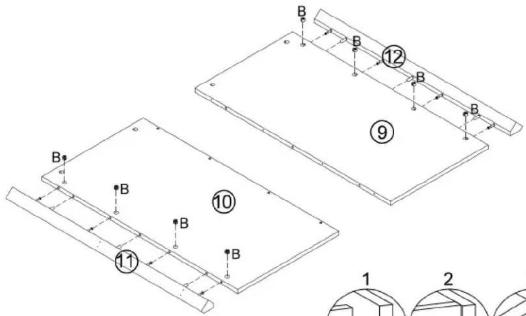
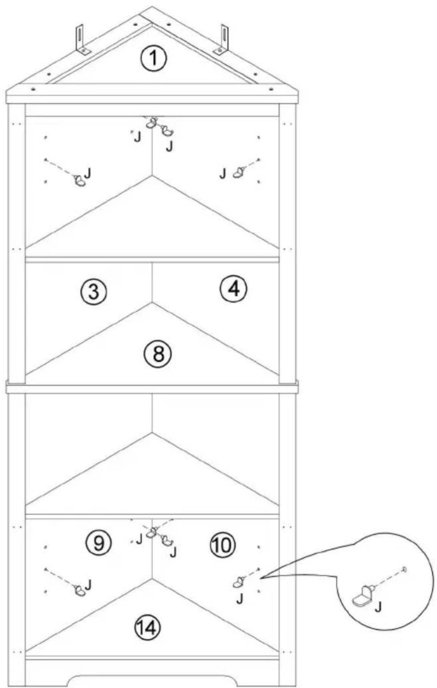
Step 10
| N | 2 |

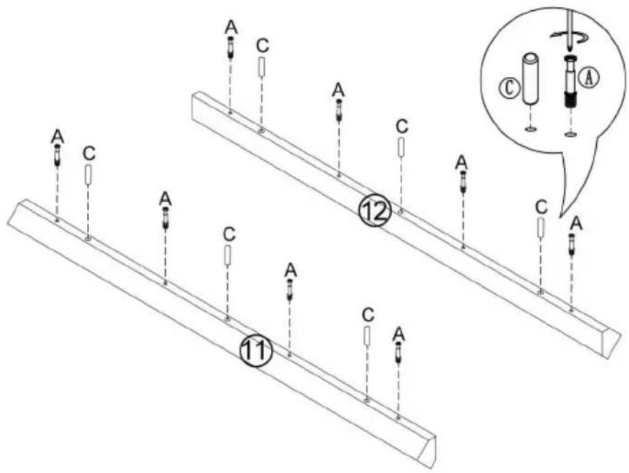
Step 11
| A | 8 | |
| C | 6 |
Step 12
| B | 8 |

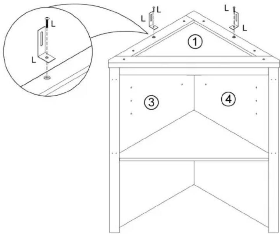
Step 15


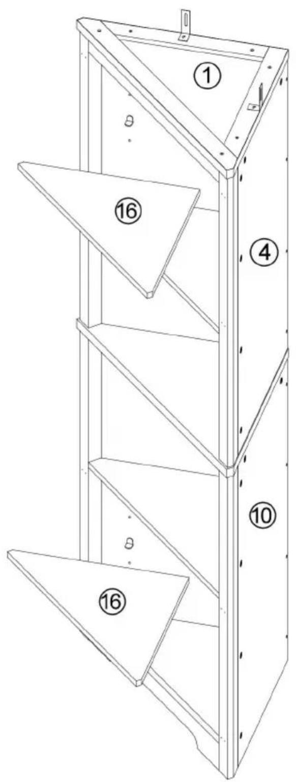
Step 16

Step 17
| G | 2 | |
| N | 4 |

Step 18
| A | 6 | |
| C | 2 |

Step 19
| B | 2 |

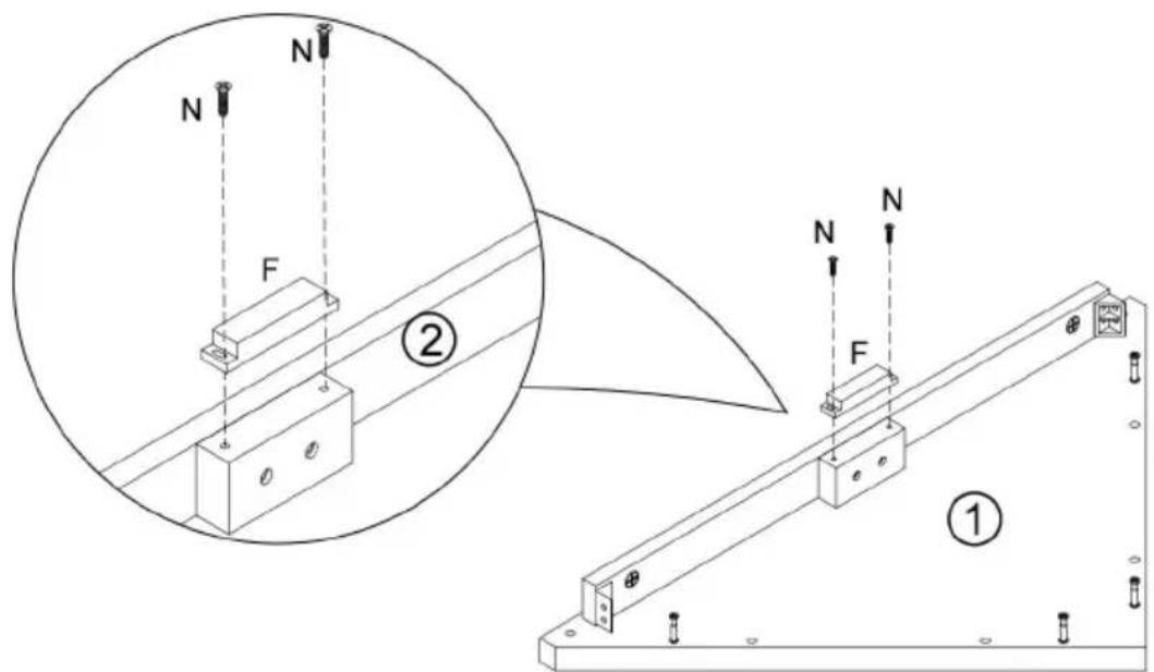
Step 20
| F | 1 | |
| N | 2 |

Step 21


Step 22

Step 24


Step 25
| A | 4 |

Step 26
| C | 6 |

Step 27
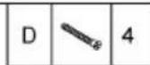
| D | 4 |
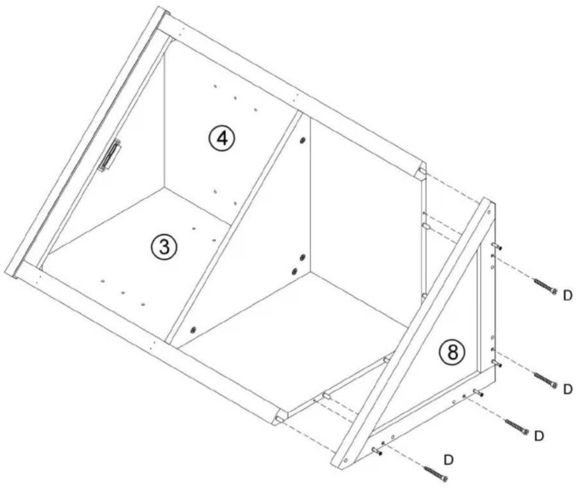
Step 28


Step 29


Step 30


Step 31

Step 32
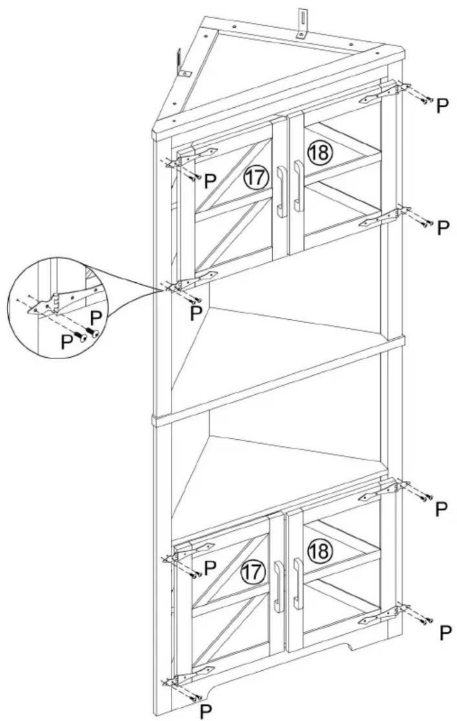
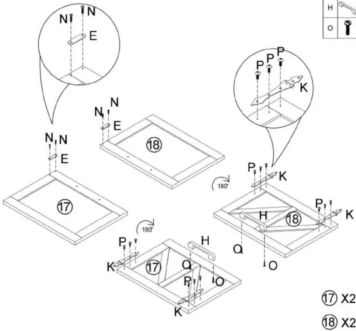
| E | 4 | |
| N | 8 | |
| P | 24 | |
| K | 8 | |
| H | 4 | |
| O | 8 |

Step 33
| P | 16 |

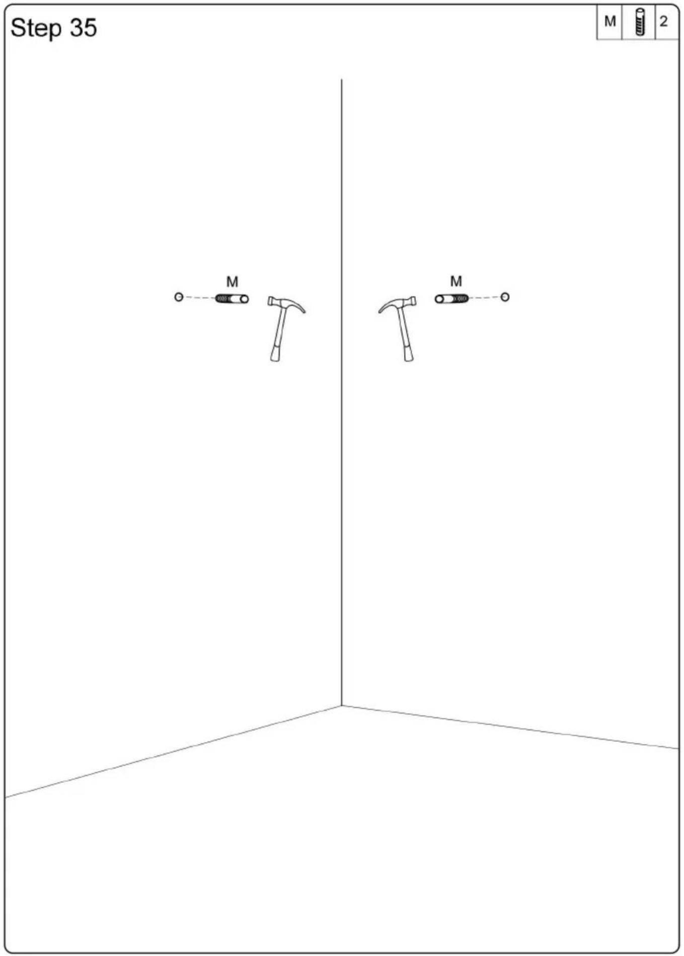
Step 34


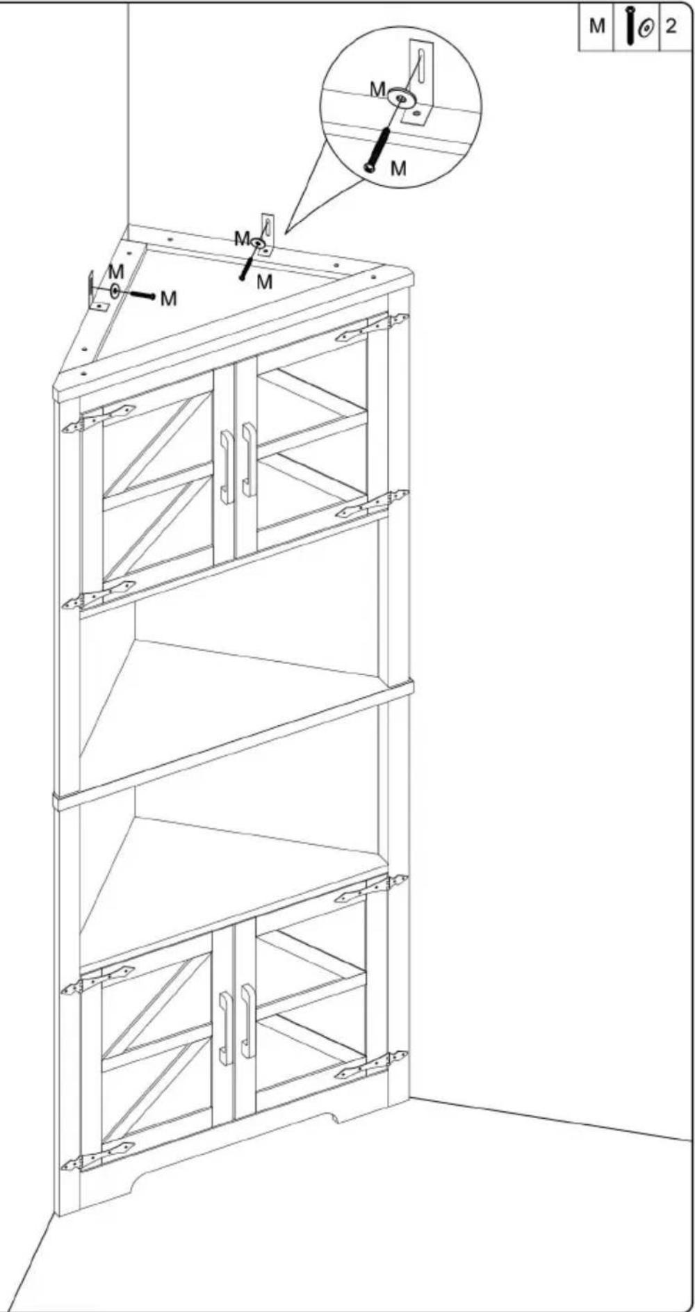
Step 36


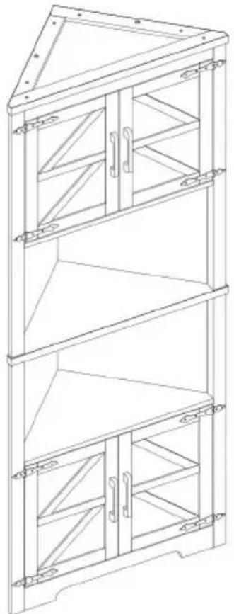
COMPLETION

natural_image
Line drawing of a three-tiered cabinet or shelf unit with triangular top and three lower panels, no text or symbols present.Manufacturer: Shanghaimuxinmuyeyouxiangongsi
Address: Shuangchenglu 803nong11hao1602A-1609shi, baoshanqu, shanghai 200000 CN.
Imported to AUS: SIHAO PTY LTD. 1 ROKEVA STREETEASTWOOD NSW 2122 Australia
Imported to USA: Sanven Technology Ltd. Suite 250, 9166 Anaheim Place, Rancho Cucamonga, CA 91730
| EC | REP |
E-CrossStu GmbH
Mainzer Landstr.69, 60329 Frankfurt am Main
| UK | REP |
YH CONSULTING LIMITED.
C/O YH Consulting Limited Office 147, Centurion House, London Road, Staines-upon-Thames, Surrey TW18 4AX
VEVOR®
TOUGH TOOLS, HALF PRICE
Technical Support and E-Warranty Certificate
www.vevor.com/support
VEVOR®
TOUGH TOOLS, HALF PRICE
Triangle Corner Cabinet
natural_image
Line drawing of a multi-tiered cabinet or enclosure structure with no text or symbolsBESOIN D'AIDE? CONTACTEZ-NOUS!
Please read and observe carefully all the assembly instructions before beginning assembly.
Unit should be assembled by two or more people.

DO NOT CLIMB
Please do not let your child climb on the product. If y kids or animals who like to climb, we highly recomme using the wall anchors and brackets/straps that come the package.
| 41X+4X | [B∅15*1241X+4X | [C∅8x30mm46X+4X | [D∅6.3*50mm12X+1X |
| [E4X] | [F2X] | [G4X] | [H4X] |
| [I41X+4X] | [J8X] | [K8X] | [L2X] |
| [M2X] | [N∅3.5*15mm28X+2X] | [O∅5/32"×20mm8X] | [P∅3.5*15mm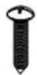 40X+4X] 40X+4X] |
ASSEMBLY STEPS
Step 1
| A | 8 | |
| C | 6 |

Step 2
| B | 8 |

Step 4
| A | 3 | |
| C | 2 | |
| G | 2 | |
| N | 4 |

Step 5
| B | 3 |


Step 10
| N | 2 |

Step 11
| A | 8 | |
| C | 6 |

Step 12
| B | 8 |

Step 15

Step 16


Step 17
| G | 2 | |
| N | 4 |

Step 18
| A | 6 | |
| C | 2 |
Step 19
| B | 2 |

Step 20
| F | 1 | |
| N | 2 |
Step 21


Step 22


Step 25
| A | 4 |

Step 26
| C | 6 |

Step 27
| D | 4 |

Step 28

Step 29

Step 30


Step 31

Step 32
| E | 4 | |
| N | 8 | |
| P | 24 | |
| K | 8 | |
| H | 4 | |
| O | 8 |

Step 33
| P | 16 |
Step 34


Step 36


COMPLETION

natural_image
Line drawing of a three-tiered cabinet or shelf structure with triangular top and horizontal shelves (no text or symbols)Fabricant : Shanghaimuxinmuyeyouxiangongsi
Adresse : Shuangchenglu 803nong11hao1602A-1609shi, baoshanqu, Shanghai 200000 CN.
Importé en Australie : SIHAO PTY LTD. 1 ROKEVA
STREETEASTWOOD NSW 2122 Australie
Anaheim Place, Rancho Cucamonga, CA 91730
| EC | REP |
| UK | REP |
E-CrossStu GmbH
Mainzer Landstr.69, 60329 Frankfurt am Main
YH CONSULTING LIMITED.
C/O YH Consulting Limited Office 147, Centurion House, London Road, Staines-upon-Thames, Surrey TW18 4AX
VEVOR®
TOUGH TOOLS, HALF PRICE
Triangle Corner Cabinet
MODELL NR.: J10030-68-FB

natural_image
Line drawing of a multi-tiered cabinet or enclosure structure with no text or symbolswww.vevor.com/support
Please read and observe carefully all the assembly instructions before beginning assembly.
Unit should be assembled by two or more people.

Please do not let your child climb on the product. If y kids or animals who like to climb, we highly recomme using the wall anchors and brackets/straps that come the package.
| A41X+4X | B∅15*1241X+4X | C∅8x30mm[GYS6]46X+4X | D∅6.3*50mm12X+1X |
| E4X | F2X | G4X | H4X |
| I41X+4X | J8X | K8X | L2X |
| M2X | N∅3.5*15mm28X+2X | O∅5/32"×20mm[2A6S]8X | P∅3.5*15mm[23KW]40X+4X |
ASSEMBLY STEPS
Step 1
| A | 8 | |
| C | 6 |

Step 2
| B | 8 |

Step 4
| A | 3 | |
| C | 2 | |
| G | 2 | |
| N | 4 |

Step 5
| B | 3 |


Step 10
| N | 2 |

Step 11
| A | 8 | |
| C | 6 |

Step 12
| B | 8 |

Step 15


Step 16

Step 17
| G | 2 | |
| N | 4 |

Step 18
| A | 6 | |
| C | 2 |

Step 19
| B | 2 |

Step 20
| F | 1 | |
| N | 2 |

Step 21


Step 22


Step 25
| A | 4 |

Step 26
| C | 6 |

Step 27
| D | 4 |

Step 28


Step 29


Step 30


Step 31

Step 32
| E | 4 | |
| N | 8 | |
| P | 24 | |
| K | 8 | |
| H | 4 | |
| O | 8 |

Step 33
| P | 16 |

Step 34


Step 36


COMPLETION

natural_image
Line drawing of a three-tiered cabinet or shelf structure with triangular top and horizontal panels (no text or symbols)Hersteller: Shanghaimuxinmuyeyouxiangongsi
Adresse: Shuangchenglu 803nong11hao1602A-1609shi, baoshanqu, Shanghai 200000 CN.
C/O YH Consulting Limited Office 147, Centurion House, London Road, Staines-upon-Thames, Surrey TW18 4AX
VEVOR®
TOUGH TOOLS, HALF PRICE
www.vevor.com/support
VEVOR®
TOUGH TOOLS, HALF PRICE
Triangle Corner Cabinet
MODELLO NUMERO: J10030-68-FB

natural_image
Line drawing of a three-tiered cabinet or shelf structure with no text or symbolsPlease read and observe carefully all the assembly instructions before beginning assembly.

Unit should be assembled by two or more people.

Please do not let your child climb on the product. If y kids or animals who like to climb, we highly recomme using the wall anchors and brackets/straps that come the package.
| 41X+4X | A∅15*1241X+4X | B∅8x30mm46X+4X | C∅6.3*50mm12X+1X |
[E] 4X 4X | F2X | G4X | H 4X 4X |
| I41X+4X | J8X | K8X | L2X |
| M2X | N∅3.5*15mm28X+2X | O∅5/32"×20mm8X | P∅3.5*15mm40X+4X |
ASSEMBLY STEPS
Step 1
| A | 8 | |
| C | 6 |

Step 2
| B | 8 |

Step 4
| A | 3 | |
| C | 2 | |
| G | 2 | |
| N | 4 |

Step 5
| B | 3 |

Step 10
| N | 2 |

Step 11
| A | 8 | |
| C | 6 |

Step 12
| B | 8 |

Step 15


Step 16


Step 17
| G | 2 | |
| N | 4 |
Step 18
| A | 6 | |
| C | 2 |

Step 19
| B | 2 |
Step 20
| F | 1 | |
| N | 2 |

Step 21
Step 22


Step 25
| A | 4 |
Step 26
| C | 6 |
Step 27
| D | 4 |

Step 28


Step 29


Step 30


Step 31
Step 32
| E | 4 | |
| N | 8 | |
| P | 24 | |
| K | 8 | |
| H | 4 | |
| O | 8 |

Step 33
| P | 16 |

Step 34


Step 36


COMPLETION

natural_image
Line drawing of a three-tiered cabinet or shelf structure with triangular top and horizontal panels (no text or symbols)Importato in AUS: SIHAO PTY LTD. 1 ROKEVA STREETEASTWOOD NSW 2122 Australia
Importato negli USA: Sanven Technology Ltd. Suite 250, 9166 Anaheim Place, Rancho Cucamonga, CA 91730
| EC | REP |
E-CrossStu GmbH
Mainzer Landstr.69, 60329 Frankfurt am Main
| UK | REP |
YH CONSULTING LIMITED.
C/O YH Consulting Limited Office 147, Centurion House, London Road, Staines-upon-Thames, Surrey TW18 4AX
VEVOR®
TOUGH TOOLS, HALF PRICE
Triangle Corner Cabinet
NÚMERO DE MODELO: J10030-68-FB
natural_image
Line drawing of a three-tiered cabinet or shelf structure with no text or symbolsPlease read and observe carefully all the assembly instructions before beginning assembly.

Unit should be assembled by two or more people.

DO NOT CLIMB
Please do not let your child climb on the product. If y kids or animals who like to climb, we highly recomme using the wall anchors and brackets/straps that come the package.
PRECAUCIONES DE MONTAJE
| A41X+4X | B∅15*1241X+4X | C∅8x30mm46X+4X | D∅6.3*50mm12X+1X |
| E4X | F2X | G4X | H4X |
| I41X+4X | J8X | K8X | L2X |
| M2X | N∅3.5*15mm[zzca]28X+2X | O∅5/32"×20mm8X | P∅3.5*15mm[xywz]40X+4X |
ASSEMBLY STEPS
Step 1
| A | 8 | |
| C | 6 |
Step 2
| B | 8 |

Step 4
| A | 3 | |
| C | 2 | |
| G | 2 | |
| N | 4 |

Step 5
| B | 3 |


Step 10
| N | 2 |

Step 11
| A | 8 | |
| C | 6 |

Step 12
| B | 8 |

Step 15


Step 16


Step 17
| G | 2 | |
| N | 4 |

Step 18
| A | 6 | |
| C | 2 |

Step 19
| B | 2 |

Step 20
| F | 1 | |
| N | 2 |

Step 21


Step 22

Step 24

Step 25
| A | 4 |
Step 26
| C | 6 |

Step 27
| D | 4 |

Step 28


Step 29


Step 30


Step 31

Step 32
| E | 4 | |
| N | 8 | |
| P | 24 | |
| K | 8 | |
| H | 4 | |
| O | 8 |

Step 33
| P | 16 |

Step 34

Step 36

COMPLETION

natural_image
Line drawing of a three-tiered cabinet or shelf structure with triangular roof and vertical panels (no text or symbols)Fabricante: Shanghaimuxinmuyeyouxiangongsi
Dirección: Shuangchenglu 803nong11hao1602A-1609shi, baoshanqu, shanghai 200000 CN.
Importado a AUS: SIHAO PTY LTD. 1 ROKEVA STREETEASTWOOD NSW 2122 Australia
Importado a EE. UU.: Sanven Technology Ltd. Suite 250, 9166 Anah Place, Rancho Cucamonga, CA 91730
| EC | REP |
E-CrossStu GmbH
Mainzer Landstr.69, 60329 Frankfurt am Main
| UK | REP |
YH CONSULTING LIMITED.
C/O YH Consulting Limited Office 147, Centurion House, London Road, Staines-upon-Thames, Surrey TW18 4AX
VEVOR®
TOUGH TOOLS, HALF PRICE
Triangle Corner Cabinet
NR MODELU: J10030-68-FB

natural_image
Line drawing of a multi-tiered cabinet or enclosure structure with no text or symbolsPOTRZEBUJESZ POMOCY? SKONTAKTUJ SIE Z NAMI!
Please read and observe carefully all the assembly instructions before beginning assembly.

Unit should be assembled by two or more people.

DO NOT CLIMB
Please do not let your child climb on the product. If y kids or animals who like to climb, we highly recomme using the wall anchors and brackets/straps that come the package.
ŚRODKI OSTROŻNOŚCI PODCZAS MONTAŻU
| A[YG2]41X+4X | B∅15*1241X+4X | C∅8x30mm46X+4X | D∅6.3*50mm12X+1X |
| E4X | F2X | G4X | H4X |
| I41X+4X | J8X | K8X | L2X |
| M2X | N∅3.5*15mm28X+2X | O∅5/32"×20mm8X | P∅3.5*15mm40X+4X |
ASSEMBLY STEPS
Step 1
| A | 8 | |
| C | 6 |

Step 2
| B | 8 |

Step 4
| A | 3 | |
| C | 2 | |
| G | 2 | |
| N | 4 |

Step 5
| B | 3 |


Step 10
| N | 2 |

Step 11
| A | 8 | |
| C | 6 |

Step 12
| B | 8 |

Step 15

Step 16


Step 17
| G | 2 | |
| N | 4 |

Step 18
| A | 6 | |
| C | 2 |

Step 19
| B | 2 |

Step 20
| F | 1 | |
| N | 2 |

Step 21
| C | 6 |

Step 22
| B | 4 |

Step 25
Step 26

Step 27
| D | 4 |

Step 28


Step 29

Step 30
Step 31

Step 32
| E | 4 | |
| N | 8 | |
| P | 24 | |
| K | 8 | |
| H | 4 | |
| O | 8 |
Step 33
| P | 16 |

Step 34


Step 36

COMPLETION
natural_image
Line drawing of a three-tiered cabinet or shelf unit with triangular top and three lower panels, no text or symbols present.Producent: Shanghaimuxinmuyeyouxiangongsi
Adres: Shuangchenglu 803nong11hao1602A-1609shi, baoshanqu, szanghaj 200000 CN.
Importowane do AUS: SIHAO PTY LTD. 1 ROKEVA
STREETEASTWOOD NSW 2122 Australia
Importowane do USA: Sanven Technology Ltd. Suite 250, 9166 Anar Place, Rancho Cucamonga, CA 91730
| EC | REP |
E-CrossStu GmbH
Mainzer Landstr.69, 60329 Frankfurt am Main
| UK | REP |
YH CONSULTING LIMITED.
C/O YH Consulting Limited Office 147, Centurion House, London Road, Staines-upon-Thames, Surrey TW18 4AX
VEVOR®
TOUGH TOOLS, HALF PRICE
www.vevor.com/support
VEVOR®
TOUGH TOOLS, HALF PRICE
Technisch Ondersteuning en E-garantiecertificaat www.vevor.com/support
DRIEHOEK HOEKKAST
GEBRUIKSAANWIJZING
MODELNUMMER: J10030-68-FB
Triangle Corner Cabinet
MODELNUMMER: J10030-68-FB

natural_image
Line drawing of a multi-tiered cabinet or shelf structure with triangular top panel and horizontal shelves (no text or symbols)HULP NODIG? NEEM CONTACT MET ONS OP!
Please read and observe carefully all the assembly instructions before beginning assembly.

Unit should be assembled by two or more people.

DO NOT CLIMB
Please do not let your child climb on the product. If y kids or animals who like to climb, we highly recomme using the wall anchors and brackets/straps that come the package.
MONTAGEVOORZORGSMAATREGELEN
| A41X+4X | B∅15*1241X+4X | C∅8x30mm46X+4X | D∅6.3*50mm12X+1X |
| E4X | F2X | G4X | H4X |
| I41X+4X | J8X | K8X | L2X |
| M2X | N∅3.5*15mm28X+2X | O∅5/32"×20mm[CSX2]8X | P∅3.5*15mm40X+4X |
ASSEMBLY STEPS
Step 1
| A | 8 | |
| C | 6 |

Step 2
| B | 8 |

Step 4
| A | 3 | |
| C | 2 | |
| G | 2 | |
| N | 4 |
Step 5
| B | 3 |

Step 10
| N | 2 |
Step 11
| A | 8 | |
| C | 6 |

Step 12
| B | 8 |
Step 15


Step 16


Step 17
| G | 2 | |
| N | 4 |

Step 18
| A | 6 | |
| C | 2 |

Step 19
| B | 2 |

Step 20
| F | 1 | |
| N | 2 |

Step 21


Step 22


Step 24

Step 25
| A | 4 |

Step 26
| C | 6 |

Step 27
| D | 4 |

Step 28

Step 29


Step 30


Step 31

Step 32
| E | 4 | |
| N | 8 | |
| P | 24 | |
| K | 8 | |
| H | 4 | |
| O | 8 |

Step 33
| P | 16 |

Step 34

Step 36


COMPLETION

natural_image
Line drawing of a three-tiered cabinet or shelf structure with triangular top and horizontal panels (no text or symbols)Fabrikant: Shanghaimuxinmuyeyouxiangongsi
Adres: Shuangchenglu 803nong11hao1602A-1609shi, baoshanqu, shanghai 200000 CN.
C/O YH Consulting Limited Office 147, Centurion House, London Road, Staines-upon-Thames, Surrey TW18 4AX
VEVOR®
TOUGH TOOLS, HALF PRICE
www.vevor.com/support
VEVOR®
TOUGH TOOLS, HALF PRICE
Triangle Corner Cabinet
MODELLNR: J10030-68-FB

natural_image
Line drawing of a multi-tiered cabinet or enclosure structure with no text or symbolsBEHÖVER HJÄLP? KONTAKTA OSS!
Please read and observe carefully all the assembly instructions before beginning assembly.

Unit should be assembled by two or more people.

Please do not let your child climb on the product. If y kids or animals who like to climb, we highly recommend using the wall anchors and brackets/straps that come the package.
FÖRSIKTIGHETSÅTGÄRDER FÖR MONTERING
| A41X+4X | B∅15*1241X+4X | C∅8x30mm46X+4X | D∅6.3*50mm12X+1X |
| E4X | F2X | G4X | H4X |
| I41X+4X | J8X | K8X | L2X |
| M2X | N∅3.5*15mm28X+2X | O∅5/32"×20mm8X | P∅3.5*15mm[66X7]40X+4X |
ASSEMBLY STEPS
Step 1
| A | 8 | |
| C | 6 |

Step 2
| B | 8 |

Step 4
| A | 3 | |
| C | 2 | |
| G | 2 | |
| N | 4 |

Step 5
| B | 3 |


Step 10
| N | 2 |
Step 11
| A | 8 | |
| C | 6 |

Step 12
| B | 8 |

Step 15


Step 16


Step 17
| G | 2 | |
| N | 4 |

Step 18
| A | 6 | |
| C | 2 |

Step 19
| B | 2 |

Step 20
| F | 1 | |
| N | 2 |

Step 21
| C | 6 |

Step 22
| B | 4 |

Step 25
| A | 4 |

Step 26
| C | 6 |

Step 27
| D | 4 |

Step 28


Step 29


Step 30


Step 31

Step 32
| E | 4 | |
| N | 8 | |
| P | 24 | |
| K | 8 | |
| H | 4 | |
| O | 8 |

Step 33
| P | 16 |

Step 34


Step 36


COMPLETION

natural_image
Line drawing of a three-tiered cabinet or shelf structure with triangular roof and vertical panels (no text or symbols)Tillverkare: Shanghaimuxinmuyeyouxiangongsi
Adress: Shuangchenglu 803nong11hao1602A-1609shi, baoshanqu, shanghai 200000 CN.
Importerad till AUS: SIHAO PTY LTD. 1 ROKEVA STREETEASTWOC NSW 2122 Australien
Importerad till USA: Sanven Technology Ltd. Suite 250, 9166 Anaheim Place, Rancho Cucamonga, CA 91730
| EC | REP |
E-CrossStu GmbH
Mainzer Landstr.69, 60329 Frankfurt am Main
| UK | REP |
YH CONSULTING LIMITED.
C/O YH Consulting Limited Office 147, Centurion House, London Road, Staines-upon-Thames, Surrey TW18 4AX
VEVOR®
TOUGH TOOLS, HALF PRICE
www.vevor.com/support