
MNF1400 - Power tool SCHEPPACH - Free user manual and instructions
Find the device manual for free MNF1400 SCHEPPACH in PDF.

| Product type | Wall chaser (disc cutter) |
| Brand | Scheppach |
| Model | MNF1400 |
| Rated voltage | 230 V~, 50 Hz |
| Rated power input | 1350 W |
| No-load speed | 9000 rpm |
| Disc diameter | 125 mm |
| Positioning bore | 22.2 mm |
| Groove depth | 0 - 30 mm |
| Adjustable groove widths | 8 - 26 mm |
| Spindle thread | M14 |
| Protection class | II (double insulation) |
| Weight | 4 kg |
| Sound pressure level (L_pA) | 97.6 dB(A) |
| Sound power level (L_WA) | 108.6 dB(A) |
| Vibration (main handle) | 6.417 m/s² (K=1.5 m/s²) |
| Dust extraction connection | Yes, with included adapter |
| Groove depth adjustment | By depth stop and locking screw |
| Spindle lock | Yes, for disc change |
| Auxiliary handle | Yes |
| Required safety equipment | Safety glasses, hearing protection, dust mask |
| Compatible materials | Concrete, masonry (asbestos-free) |
| Maintenance | Regularly clean ventilation slots; replace power cord by a professional |
Frequently Asked Questions - MNF1400 SCHEPPACH
User questions about MNF1400 SCHEPPACH
0 question about this device. Answer the ones you know or ask your own.
Ask a new question about this device
Download the instructions for your Power tool in PDF format for free! Find your manual MNF1400 - SCHEPPACH and take your electronic device back in hand. On this page are published all the documents necessary for the use of your device. MNF1400 by SCHEPPACH.
USER MANUAL MNF1400 SCHEPPACH
natural_image
Exterior view of a modern electric saw with a black handle and control panel (no visible text or symbols)MNF1400
| DE | MauernutfräseOriginal-Anleitung | 5 -12 |
| GB | Masonry channel cutterTranslation from the original instruction manual | 13 - 19 |
| FR | Fraise à rainure de murTraduction des instructions d'origine | 20 - 27 |
| IT | Scanalatrice per muroTraduzione dalle istruzioni d'uso originali | 28 - 35 |
| CZ | Drážkovací frézku na zdivoPřeklad originálního návodu k obsluze | 36 - 43 |
| HU | FalhoronymaróAz eredeti használati útmutató fordítása | 44 - 51 |
| EE | SoonefreesTõlkimine juhiseld | 52 - 58 |
| LT | Mūra gropju frēzeVertimas originalios operacinės vadove | 59 - 65 |
| LV | Mūro griovelių frezaTulkojums no sākotnējā ekspluatācijas rokasgrāmatā | 66 - 72 |
| SK | Drážkovacia fréza na murivoPreklad originálu návodu na obsluhu | 73 - 80 |
1
flowchart
graph TD
    A["1417"] --> B["13"]
    A --> C["5"]
    D[" "] --> E[" "]
    F[" "] --> G[" "]
    H[" "] --> I[" "]
    J[" "] --> K[" "]
    L[" "] --> M[" "]
2
3
4
natural_image
Cross-sectional view of a mechanical device with internal components and labeled part '17' (no text or symbols beyond label)5
6
Günzburger Straße 69
D-89335 Ichenhausen
Verehrter Kunde,
Explanation of the symbols on the equipment

GB
Caution - Read the operating instructions to reduce the risk of inquiry

GB
Wear safety goggles!

GB
Wear ear-muffs!

GB
Wear a breathing mask!

GB
protection class II
Introduction
MANUFACTURER:
scheppach
Günzburger Straße 69
D-89335 Ichenhausen
Dear Customer,
We hope your new tool brings you much enjoyment and success.
NOTE:
According to the applicable product liability laws, the manufacturer of the device does not assume liability for damages to the product or damages caused by the product that occurs due to:
- Improper handling,
• Non-compliance of the operating instructions, - Repairs by third parties, not by authorized service technicians,
- Installation and replacement of non-original spare parts,
• Application other than specified, - A breakdown of the electrical system that occurs due to the non-compliance of the electric regulations and VDE regulations 0100, DIN 57113 / VDE0113.
We recommend:
Read through the complete text in the operating instructions before installing and commissioning the device. The operating instructions are intended to help the user to become familiar with the machine and take advantage of its application possibilities in accordance with the recommendations. The operating instructions contain important information on how to operate the machine safely, professionally and economically, how to avoid danger, costly repairs, reduce downtimes and how to increase reliability and service life of the machine.
In addition to the safety regulations in the operating instructions, you have to meet the applicable regulations that apply for the operation of the machine in your country. Keep the operating instructions package with the machine at all times and store it in a plastic cover to protect it from dirt and moisture. Read the instruction manual each time before operating the machine and carefully follow its information. The machine can only be operated by persons who were instructed concerning the operation of the machine and who are informed about the associated dangers. The minimum age requirement must be complied with.
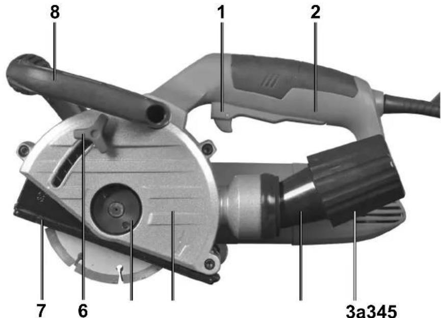
Layout (Fig. 1)
- ON/OFF switch
- Handle
- Dust extraction adapter
3a. Union nut - Blade guard
- Locking flange (with thread)
- Locking screw for the depth stop
- Depth stop
- Additional handle
- Safety lock-out
- Spindle lock
- Roller
- Reducer
- Flange
- Blotters
- Face spanner
- Hand chisel
- Backing flange
Scope of delivery
- Open the packaging and remove the device carefully.
- Remove the packaging material as well as the packaging and transport bracing (if available).
- Check that the delivery is complete.
- Check the device and accessory parts for transport damage.
- If possible, store the packaging until the warranty period has expired.
ATTENTION
The device and packaging materials are not toys! Children must not be allowed to play with plastic bags, film and small parts! There is a risk of swallowing and suffocation!
1 wall chaser
1 face spanner
1 reducer
1 hand chisel
Intended use
The wall grinder (standard nomenclature: abrasive cutting appliance), hereinafter referred to as the appliance, is designed for making cuts or slits (without the use of water) in firmly supported and primarily mineral materials such as concrete or masonry, using the guide carriage and in combination with an approved industrial dust extractor. Any other usage of or modification to the appliance is deemed to be improper and carries the risk of serious personal injury. Not for commercial use.
General Power Tool Safety Warnings
⚠ WARNING! Read all safety warnings and all instructions. Failure to follow the warnings and instructions may result in electric shock, fire and/or serious injury.
Save all warnings and instructions for future reference.
The term „power tool“ in the warnings refers to your mains-operated (corded) power tool or battery-operated (cordless) power tool.
Work area safety
- Keep work area clean and well lit. Cluttered or dark areas invite accidents.
- Do not operate power tools in explosive atmospheres, such as in the presence of flammable liquids, gases or dust. Power tools create sparks which may ignite the dust or fumes.
- Keep children and bystanders away while operating a power tool. Distractions can cause you to lose control.
Electrical safety
- Power tool plugs must match the outlet. Never modify the plug in any way. Do not use any adapter plugs with earthed (grounded) power tools. Unmodified plugs and matching outlets will reduce risk of electric shock.
- Avoid body contact with earthed or grounded surfaces, such as pipes, radiators, cookers and refrigerators. There is an increased risk of electric shock if your body is earthed or grounded.
- Do not expose power tools to rain or wet conditions. Water entering a power tool will increase the risk of electric shock.
- Do not abuse the cord. Never use the cord for carrying, pulling or unplugging the power tool. Keep cord away from heat, oil, sharp edges or moving parts. Damaged or entangled cords increase the risk of electric shock.
- When operating a power tool outdoors, use an extension cord suitable for outdoor use. Use of a cord suitable for outdoor use reduces the risk of electric shock.
- If operating a power tool in a damp location is unavoidable, use a residual current device (RCD) protected supply. Use of an RCD reduces the risk of electric shock.
Personal safety
- Stay alert, watch what you are doing and use common sense when operating a power tool. Do not use a power tool while you are tired or under the influence of drugs, alcohol or medication. A moment of inattention while operating power tools may result in serious personal injury.
- Use personal protective equipment. Always wear eye protection. Protective equipment such as dust mask, non-skid safety shoes, hard hat, or hearing
protection used for appropriate conditions will reduce personal injuries.
- Prevent unintentional starting. Ensure the switch is in the off-position before connecting to power source and/or battery pack, picking up or carrying the tool. Carrying power tools with your finger on the switch or energising power tools that have the switch on invites accidents.
- Remove any adjusting key or wrench before turning the power tool on. A wrench or a key left attached to a rotating part of the power tool may result in personal injury.
- Do not overreach. Keep proper footing and balance at all times. This enables better control of the power tool in unexpected situations.
- Dress properly. Do not wear loose clothing or jewellery. Keep your hair, clothing and gloves away from moving parts. Loose clothes, jewellery or long hair can be caught in moving parts.
- If devices are provided for the connection of dust extraction and collection facilities, ensure these are connected and properly used. Use of dust collection can reduce dust-related hazards.
Power tool use and care
- Do not force the power tool. Use the correct power tool for your application. The correct power tool will do the job better and safer at the rate for which it was designed.
- Do not use the power tool if the switch does not turn it on and off. Any power tool that cannot be controlled with the switch is dangerous and must be repaired.
- Disconnect the plug from the power source and/or the battery pack from the power tool before making any adjustments, changing accessories, or storing power tools. Such preventive safety measures reduce the risk of starting the power tool accidentally.
- Store idle power tools out of the reach of children and do not allow persons unfamiliar with the power tool or these instructions to operate the power tool. Power tools are dangerous in the hands of untrained users.
- Maintain power tools. Check for misalignment or binding of moving parts, breakage of parts and any other condition that may affect the power tool's operation. If damaged, have the power tool repaired before use. Many accidents are caused by poorly maintained power tools.
- Keep cutting tools sharp and clean. Properly maintained cutting tools with sharp cutting edges are less likely to bind and are easier to control.
- Use the power tool, accessories and tool bits etc. in accordance with these instructions, taking into account the working conditions and the work to be performed. Use of the power tool for operations different from those intended could result in a hazardous situation.
Service
- Have your power tool serviced by a qualified repair person using only identical replacement parts. This will ensure that the safety of the power tool is maintained.
Safety instructions for abrasive cutting appliances
- The blade guard, which is a part of the power tool, must be attached securely and set in a way that ensures maximum safety, i.e. the smallest possible amount of the grinding tool is exposed to the operator. Ensure that you and anyone else in the vicinity remain outside of the range of the rotating grinding disc. The blade guard is designed to protect the operator from fragments and accidental contact with the grinding tool.
- Use only diamond-coated cutting discs for your power tool. Just because you can attach the accessories to your power tool, does not ensure they are safe to use.
- The maximum speed of the accessory tool used must be at least as high as the maximum speed specified for the power tool. Accessories which rotate faster than the maximum permissible rate can break and throw pieces into the air.
- Grinding tools should only be used for the recommended applications. For example: Never grind with the side surface of a cutting disc. Cutting discs are designed to remove material with the edge of the disc. Any lateral application of force on these grinding tools can lead to breakage.
- Always use an undamaged clamping flange of the correct size and shape for the selected grinding disc. Suitable flanges support the grinding disc and reduce the risk of disc breakage.
- The external diameter and thickness of the accessory tool used must comply with the dimensions of your power tool. Incorrectly dimensioned accessory tools cannot be sufficiently shielded or controlled.
- Grinding discs and flanges must fit precisely onto the grinding spindle of your power tool. Accessory tools which do not fit precisely on the grinding spindle of the power tool will rotate unevenly, vibrate severely and can lead to a loss of control.
- Do not use damaged grinding discs. Check the grinding discs before each use for chips and cracks. If the power tool or grinding disc is dropped, check to see if it either are damaged, or use an undamaged grinding disc. After checking and inserting the grinding disc, ensure that you and any other people in the vicinity remain outside of the range of the rotating grinding disc, and allow the tool to rotate at maximum speed for one minute. Damaged grinding discs usually break during this test period.
- Wear personal protective equipment. Depending on the application, ensure that you use full face protection, eye protection or goggles. If required, use a dust mask, ear protectors, protective gloves or special apron to protect you from
grindings and material particles. Eyes should be protected from flying debris that may be generated during certain applications. Dust or filter masks must filter any dust created by the application. If you are exposed to loud noise for any length of time, you can suffer a hearing loss.
- Ensure that other people remain at a safe distance to your workspace. Anyone who enters the workspace must wear personal protective equipment. Fragments of the workpiece or broken accessory tools can fly off and cause injury – even outside the immediate working area.
- Hold power tool by the insulated gripping surfaces, when performing an operation where the accessory tool may contact hidden wiring or its own cord. Contact with a „live“ wire may make exposed metal parts of the power tool „live“ and could give the operator an electric shock.
- Keep the power cord away from any rotating accessories. If you lose control of the appliance, the cord may get cut or caught and your hand or arm could get caught in the rotating accessory tool.
- Never put the power tool down until the accessory tool has come to a complete standstill. The rotating accessory tool could come into contact with the surface and cause you to lose control of the power tool.
- Do not leave the power tool running whilst carrying it. Accidental contact between your clothing and the rotating accessory tool could cause your clothing to get caught and the accessory tool to penetrate a part of your body.
- Clean the ventilation slits of your power tool regularly. The engine fan draws dust into the housing and a strong accumulation of metal dust can cause electrical hazards.
- Do not use the power tool in the vicinity of flammable materials. Sparks can ignite such materials.
- Do not use any accessory tools which require liquid coolant. The use of water or other liquid coolants may lead to electric shock.
Further safety instructions for abrasive cutting applications
Kickback and corresponding safety instructions Kickback - causes and corresponding safety instructions
- Kickback is a sudden reaction caused when a rotating grinding disc catches or jams. Catching or jamming causes the rotating accessory tool to stop abruptly. If this happens, an uncontrolled power tool turns rapidly against the direction of rotation of the accessory tool caught in the blockage.
- If, for example, a grinding disc catches or jams, the edge of the grinding disc that is projecting into the workpiece can get caught and break off the grinding disc or cause a kickback. The grinding disc can then fly in the direction of the operator or away from him, depending on the direction of rotation of the disc at the blockage. This can also break grinding discs.
A kickback is caused by incorrect use or misuse of the power tool. This can be avoided by taking proper precautions as given below.
- Hold the power tool firmly in both hands and position your arms so they can absorb the force of a kickback. Always use the additional handle, if available, so you have the maximum control over the kickback force or reaction torques at full speed. By taking adequate precautions, the operator can stay in control of the kickback and reaction torques.
- Never hold your hand close to a rotating accessory tool. The accessory tool could hit your hand in the case of a kickback.
- Avoid the area in front of and behind the rotating cutting disc. The kickback will force the power tool in the opposite direction to the direction of rotation of the grinding disc at the blockage.
- Take special care when working around corners, sharp edges, etc. Avoid allowing the accessory tool to bounce back from the workpiece or jam. The rotating accessory tool is more likely to jam in corners or sharp edges or if it bounces. This can cause a loss of control or kickback.
- Do not use a toothed or chain saw blade or segmented diamond-coated disc with more than 10 mm wide slits. Such accessory tools cause a kick-back or loss of control over the power tool.
- Avoid cutting disc jams or excessive contact pressure. Do not make any excessively deep cuts. Overloading the cutting disc increases the stress and likelihood of tilting or jamming and thus the possibility of kickback or breakage of the grinding tool.
- If the cutting disc jams or you stop working, switch the tool off and hold it steady until the disc has completely stopped turning. Never attempt to pull a rotating cutting disc out of a cut. This could lead to kickback. Identify and remove the cause of the jam.
- Do not switch the power tool back on as long as it is in the workpiece. Allow the cutting disc to reach its full speed before you carefully continue the cut. Otherwise, the disc may jam, jump out of the workpiece or cause kickback.
- Support panels or large workpieces to reduce the risk of the cutting disc jamming and causing a kickback. Large workpieces can bend under their own weight. The workpiece must be supported on both sides, namely in the vicinity of the cut and also at the edge.
- Be particularly careful when making „pocket cuts“ into existing walls or other obscured areas. The inserted cutting disc may cut into gas or water pipes, electrical wiring or other objects that can cause kickback.
Technical data
| Input voltage 230 V~, 50 Hz |
| Power consumption 1350 W |
| Rated speed 9000 /min |
| Disc sizes ∅ 125 mm |
| Central fixing bore 22.2 mm |
| Groove depth 0 - 30 mm |
| Groove widths 8 - 26 mm |
| Thread M14 |
| Protection class II |
| Weight 4 kg |
Noise
Total noise values determined in accordance with EN 60745.
| sound pressure level L_pA | 97.6 dB(A) |
| uncertainty K_pA | 3 dB(A) |
| sound power level L_WA | 108.6 dB(A) |
| uncertainty K_WA | 3 dB(A) |
Wear hearing protection.
The effects of noise can cause a loss of hearing.
Total vibration values (vector total of three directions) determined in accordance with EN 60745. Details of vibration values (when cutting off a concrete plate): Main handle: a_h=6,417 m/s^2
Uncertainty K = 1,5 m/s ^4
NOTE: The vibration level specified in these instructions has been measured in accordance with a standardised measuring procedure specified in EN 60745 and can be used to make equipment comparisons. The specified vibration emission value can also be used to make an initial exposure estimate.
⚠ WARNING! The vibration level varies in accordance with the use of the power tool and may be higher than the value specified in these instructions in some cases. There is a risk of underestimation of the vibration load if the power tool is used regularly in this manner. Try to keep the vibration loads as low as possible.
Measures to reduce the vibration load are, e.g. wearing gloves and limiting the working time. Wherein all states of operation must be included (e.g. times when the power tool is switched off and times where the power tool is switched on but running without load).
Residual risks
Even if you use this electric power tool in accordance with instructions, certain residual risks cannot be rules out. The following hazards may arise in connection with the equipment's construction and layout:
- Lung damage if no suitable protective dust mask is used.
- Damage to hearing if no suitable ear protection is used.
- Health damage caused by hand-arm vibrations if the equipment is used over a prolonged period or is not properly guided and maintained.
Before use
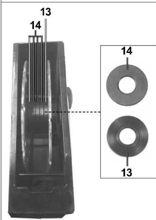
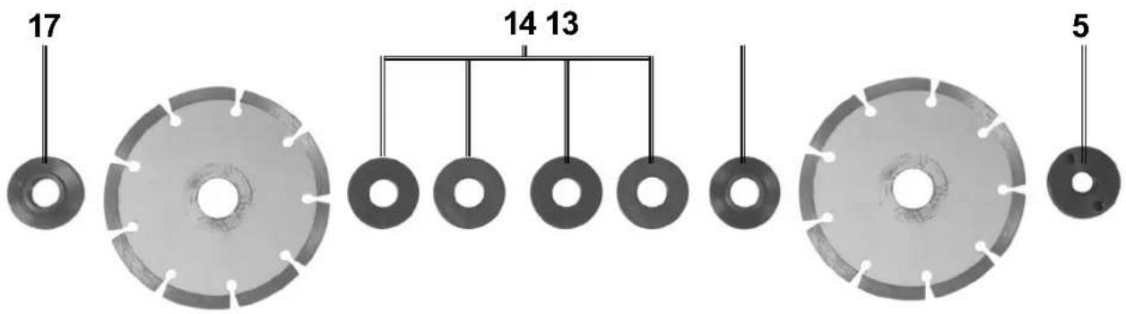
Setting the cut width of the diamond cutting discs (Abb.1)
- Loosen the locking screw (6).
- Push the depth stop (7) upwards.
- Press the spindle lock (10) and hold it down.
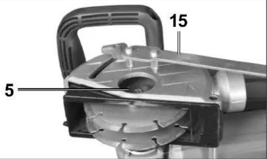
- Use the face spanner (15) to loosen the locking flange (5).
- Remove the locking flange (5).
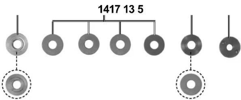
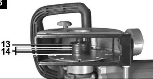
- Set the desired cut width in accordance with the number of blotters (14). Ensure that the flange(13) is set in place as the top intermediate layer (Fig.2).
NOTE
- There are several spacer washers available for you. Ensure that the groove width is the total of the spacer washers between the diamond cutting discs and the thickness of the cutting discs.
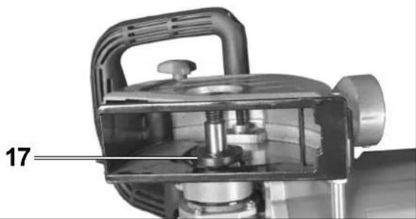
- Please make sure that the backing flange (17) is fixed well on the shaft. The backing flange must rotate with shaft.
- Please make sure that diamond disc fixed well on the flanges (13+17).
- Tighten the locking flange (5) using the face spanner (15). Press the spindle lock(10) while doing this..
NOTE
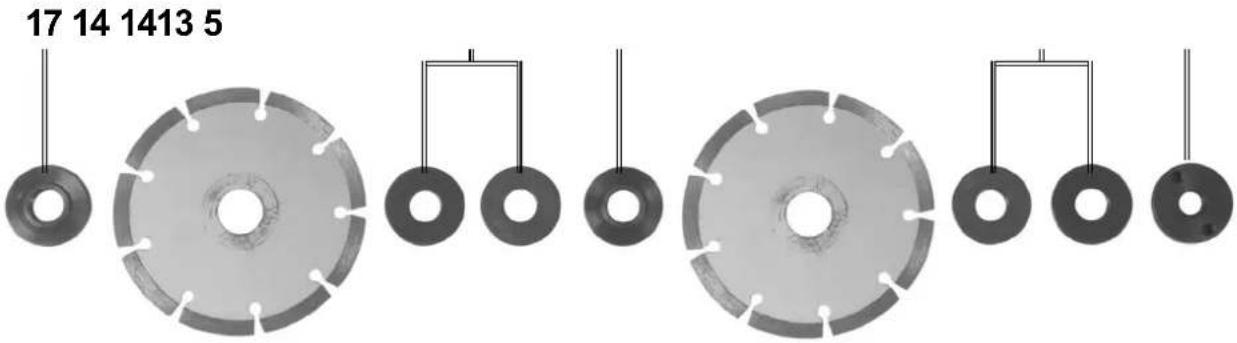
- When setting a cut width that is smaller than the maximum cut width, you must use the blotters on the fixing flange side for fixing the cutting discs since the fixing flange cannot fix the discs alone on the spindle due to the thread length (Fig.3).
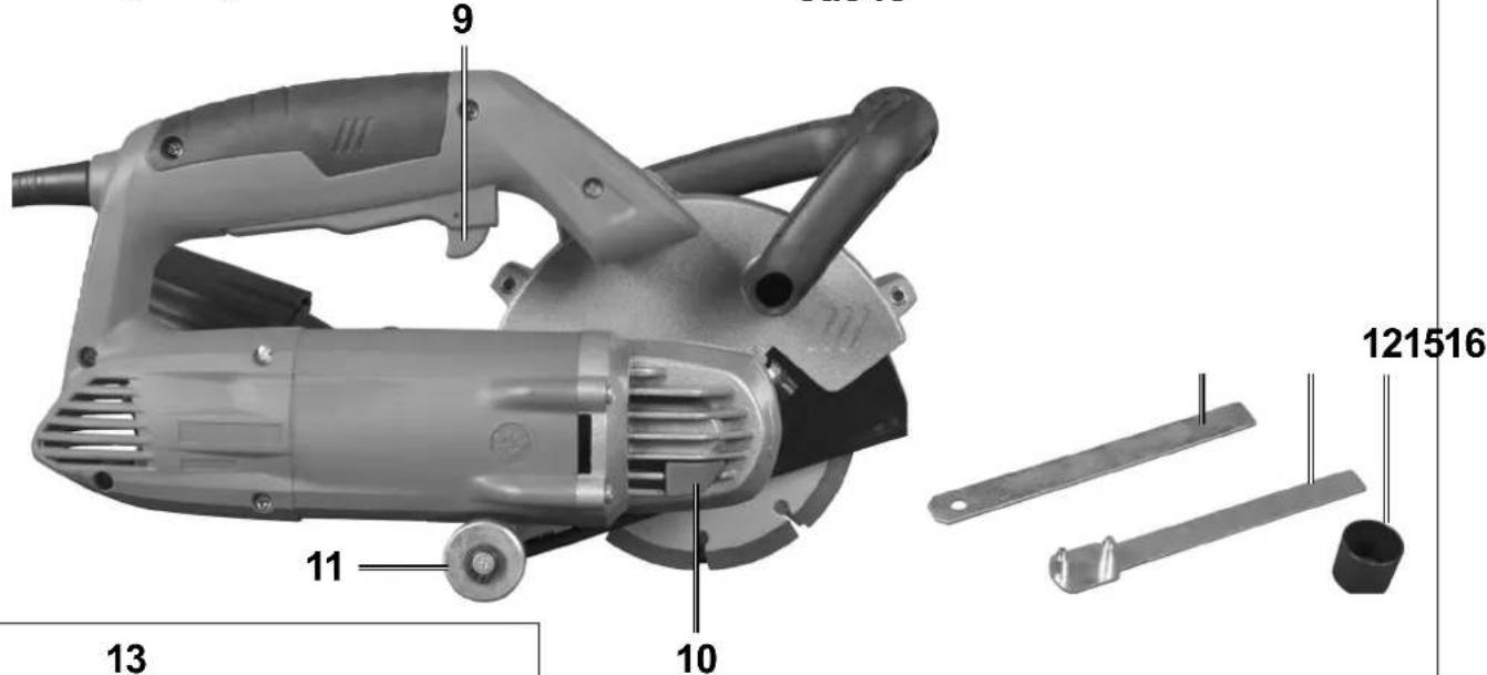
Replacing the diamond cutting discs (Fig. 1 / 4 / 5 / 6)
NOTE
- Replace diamond cutting discs only in pairs.
- Loosen the locking screw (6).
- Push the depth stop (7) upwards.
- Press the spindle lock (10) and hold it down.
- Use the face spanner (15) to loosen the locking flange(5).
• Take off all removable parts from the spindle. - Clean the locking flange (5), flange (13), blotters (14) and backing flange (17) thoroughly.
- Attach the backing flange (17) (Fig. 4).
NOTE
- Make sure that the backing flange (17) is correctly attached by ensuring that it rotates together with the spindle.
- Attach the first diamond cutting disc (Fig. 5).
- Set the desired cut width in accordance with
- the number of blotters (14). Ensure that the flange
(13)is set in place as the top blotter (Fig. 5).
- Attach the second diamond cutting disc (Fig. 6).
NOTE
- Make sure that the cutting discs are correctly attached to the flanges.
- Tighten the locking flange (5) using the face spanner (15)Press the spindle lock (10) while doing this (Fig. 1 +6).
Setting the groove depth (Fig. 1)
- Loosen the locking screw (6).
- Set the depth stop (7) to the desired depth.
- Tighten the locking screw (6).
Attaching the dust extraction adapter (Fig. 1)
- Push the pins of the dust extraction adapter (3) into the recesses on the dust extraction connector.
- Lock the dust extraction adapter (3) by turning it.
- Loosen the union nut (3a).
- Push the pipe of the extraction device far enough into the opening on the union nut(3a).
- Tighten the union nut (3a) fully.
Bedienung
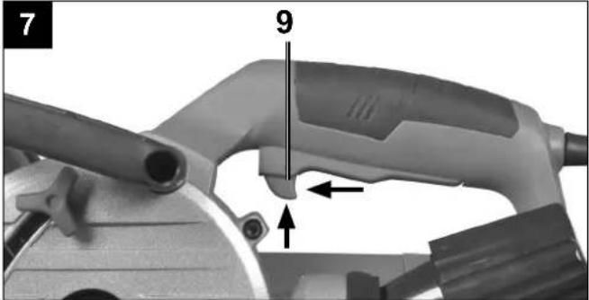
Switching on and off (Fig. 7)
NOTE
Always switch the appliance on before making contact with the material, then apply it to the workpiece. The wall grinder is equipped with an electronic smooth start. The motor starts with a delay.
Switching the appliance on:
- Activate the safety lock-out (9) (see fold-out page). Then press the ON/OFF switch (1).
Switching the appliance off:
- Release the ON/OFF switch (1).
Handling the wall grinder
CAUTION!
This appliance is designed for dry cutting only!
- Use a service line detector to check the internal and external walls for concealed power, gas and water supply lines before using the wall chaser.
-
Select the desired groove width.
-
Position the appliance with the roller (11) against the brick wall.
- Now switch the appliance on and plunge it into the masonry until the stop (7) makes contact.
- Then mill the groove in the masonry; pay attention to the milling direction. The appliance must always run in reverse rotation. Otherwise the appliance could be pushed out of the cut in an uncontrolled manner.
- At the end of the groove, swivel the appliance out of the groove and only then switch the appliance off.
- Now break out the resulting bar between the two grooves using the hand chisel (16).
⚠️ CAUTION!
Materials containing asbestos must not be machined!
Maintenance and cleaning
⚠ WARNING! RISK OF INJURY! Switch the appliance off and remove the power plug before commencing any work to the appliance.
- The appliance must always be kept clean, dry and free from oil or grease.
- Use a soft, dry cloth to clean the housing. Never use petrol, solvents or cleansers which can damage plastic.
⚠ WARNING! If the connecting cable needs to be replaced, this must be carried out by the manufacturer or an authorised representative in order to avoid safety hazards.
- Grinding tools are to be treated with care and transported carefully. Grinding tools should be stored in such a way that they are not exposed to mechanical damage or harmful environmental influences.
- Never allow liquids to get into the appliance.
Storage
Store the device and its accessories in a dark, dry and frost-proof place that is inaccessible to children. The optimum storage temperature is between 5 and 30°C. Store the electrical tool in its original packaging. Cover the electrical tool in order to protect it from dust and moisture.
Store the operating manual with the electrical tool.
Electrical connection
The electrical motor installed is connected and ready for operation. The connection complies with the applicable VDE and DIN provisions.
The customer's mains connection as well as the extension cable used must also comply with these regulations.
Important information
In the event of an overloading the motor will switch itself off. After a cool-down period (time varies) the motor can be switched back on again.
Damaged electrical connection cable
The insulation on electrical connection cables is often damaged.
This may have the following causes:
- Passage points, where connection cables are passed through windows or doors.
- Kinks where the connection cable has been improperly fastened or routed.
- Places where the connection cables have been cut due to being driven over.
- Insulation damage due to being ripped out of the wall outlet.
- Cracks due to the insulation ageing.
Such damaged electrical connection cables must not be used and are life-threatening due to the insulation damage.
Check the electrical connection cables for damage regularly. Make sure that the connection cable does not hang on the power network during the inspection. Electrical connection cables must comply with the applicable VDE and DIN provisions. Only use connection cables with the marking „H05VV-F“.
The printing of the type designation on the connection cable is mandatory.
AC motor
- The mains voltage must be 230 V\~
- Extension cables up to 25 m long must have a cross-section of 1.5 mm2.
Connections and repairs of electrical equipment may only be carried out by an electrician.
Please provide the following information in the event of any enquiries:
• Type of current for the motor
• Machine data - type plate
• Machine data - type plate
Disposal and recycling
The equipment is supplied in packaging to prevent it from being damaged in transit. The raw materials in this packaging can be reused or recycled. Never place batteries in your household refuse, in fire or in water. Batteries should be collected, recycled or disposed of by environment-friendly means. The equipment and its accessories are made of various types of material, such as metal and plastic. Defective components must be disposed of as special waste. Ask your dealer or your local council.
Old devices must not be disposed of with household waste!

This symbol indicates that this product must not be disposed of together with domestic waste in compliance with the Directive (2012/19/EU) pertaining to waste electrical and electronic equipment (WEEE). This product must be disposed of at a designated collection point. This can occur, for example, by handing it in at an authorised collecting point for the recycling of waste electrical and electronic equipment. Improper handling of waste equipment may have negative consequences for the environment and human health due to potentially hazardous substances that are often contained in electrical and electronic equipment. By properly disposing of this product, you are also contributing to the effective use of natural resources. You can obtain information on collection points for waste equipment from your municipal administration, public waste disposal authority, an authorised body for the disposal of waste electrical and electronic equipment or your waste disposal company.
Günzburger Straße 69
D-89335 Ichenhausen
Chers clients,
Günzburger Straße 69
D-89335 Ichenhausen
Egregio cliente,
Günzburger Straße 69
D-89335 Ichenhausen
TISZTELT VÁSÁRLÓ!
Günzburger Straße 69
D-89335 Ichenhausen
Hea klient,
Günzburger Straße 69
D-89335 Ichenhausen
Gerbiamas Kliente,
Günzburger Straße 69
D-89335 Ichenhausen
Cienijamais klient,
Günzburger Straße 69
D-89335 Ichenhausen
Vážený zákazník,
Subject to change without notice
Documents registar: Georg Kohler
Günzburger Str. 69,
89335 Ichenhausen; Germany
Garantie DE
Apparent defects must be notified within 8 days from the receipt of the goods. Otherwise, the buyeris rights of claim due to such defects are invalidated. We guarantee for our machines in case of proper treatment for the time of the statutory warranty period from delivery in such a way that we replace any machine part free of charge which provably becomes unusable due to faulty material or defects of fabrication within such period of time. With respect to parts not
manufactured by us we only warrant insofar as we are entitled to warranty claims against the upstream suppliers. The costs for the installation of the new parts shall be borne by the buyer. The cancellation of sale or the reduction of purchase price as well as any other claims for damages shall be excluded.