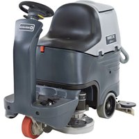
SC3000 EcoFlex - Floor cleaner ADVANCE - Free user manual and instructions
Find the device manual for free SC3000 EcoFlex ADVANCE in PDF.


| Product type | Floor scrubber for smooth floors |
| Brand | Advance |
| Model | SC3000 EcoFlex |
| Cleaning width | 660 mm (26 in) or 710 mm (28 in) depending on version |
| Squeegee width | 890 mm (35 in) |
| Machine height | 1,190 mm (46.8 in) |
| Machine length | 1,360 mm (53.5 in) |
| Machine width (without squeegee) | 670 mm (26.4 in) or 810 mm (31.9 in) |
| Empty weight (without batteries) | 175 kg (385.8 lb) or 180 kg (396.8 lb) |
| Maximum operating weight | 446 kg (983.2 lb) or 451 kg (994.3 lb) |
| Solution/water tank capacity | 80 L (21 US gal) |
| Battery type | 4 x 6 V, 180 Ah C5 (WET or GEL/AGM) |
| Supply voltage | 24 V |
| Suction motor power | 420 W (0.56 HP) |
| Traction motor power | 300 W (0.4 HP) |
| Brush motor power (disc version) | 2 x 400 W (2 x 0.53 HP) |
| Maximum speed | 6 km/h (3.7 mph) |
| Sound pressure level | 65 dB(A) ± 3 dB(A) |
| Main functions | Washing and drying, EcoFlex system (detergent mixing), silent mode, extra brush pressure, anti-slip system |
| Safety | Emergency button, seat microswitch, electromagnetic brake, overload protection |
| Maintenance and cleaning | Daily cleaning of squeegee, brushes, tanks, filters; draining the EcoFlex system |
| Spare parts and repairability | Use only original parts; contact Advance technical support for repairs |
| Operating temperature | 0 °C to +40 °C (32 °F to 104 °F) |
Frequently Asked Questions - SC3000 EcoFlex ADVANCE
User questions about SC3000 EcoFlex ADVANCE
0 question about this device. Answer the ones you know or ask your own.
Ask a new question about this device
Download the instructions for your Floor cleaner in PDF format for free! Find your manual SC3000 EcoFlex - ADVANCE and take your electronic device back in hand. On this page are published all the documents necessary for the use of your device. SC3000 EcoFlex by ADVANCE.
USER MANUAL SC3000 EcoFlex ADVANCE
natural_image
Line drawing of a cleaning or cleaning service robot with visible internal components (no text or symbols)
INSTRUCTION FOR USE INSTRUCTIONS D'UTILISATION INSTRUCCIONES DE USO INSTRUÇÕES DE USO
Advance models: 9087266020 - 26" Disc - Charger 9087267020 - 26" Disc - EcoFlex™ + Charger 9087268020 - 28" Cyl. - Charger 9087269020 - 28" Cyl. - EcoFlex™ + Charger
ENGLISH
FRANÇAIS
ESPAÑOL
PORTUGUÊS
TABLE OF CONTENTS
INTRODUCTION....2
MANUAL PURPOSE AND CONTENTS 2
TARGET....2
HOW TO KEEP THIS MANUAL....2
IDENTIFICATION DATA....2
OTHER REFERENCE MANUALS....2
SPARE PARTS AND MAINTENANCE....2
CHANGES AND IMPROVEMENTS 2
OPERATION CAPABILITIES....2
CONVENTIONS 2
UNPACKING/DELIVERY 3
SAFETY 3
SYMBOLS 3
GENERAL INSTRUCTIONS....4
MACHINE DESCRIPTION....6
MACHINE STRUCTURE 6
STEERING WHEEL WITH CONTROL PANEL 8
ACCESSORIES/OPTIONS....9
TECHNICAL DATA....9
WIRING DIAGRAM....10
USE 12
BATTERY CHECK/SETTING ON A NEW MACHINE....12
BATTERY INSTALLATION AND BATTERY TYPE SETTING (WET OR GEL/AGM) 13
BEFORE START-UP....14
MACHINE START AND STOP 17
MACHINE OPERATION (SCRUBBING/DRYING)....18
TANK EMPTYING....20
AFTER USING THE MACHINE....21
PUSHING/TOWING THE MACHINE 21
FIRST PERIOD OF USE 22
MAINTENANCE 22
SCHEDULED MAINTENANCE TABLE 22
MACHINE WORKING HOUR CHECK 22
SQUEEGEE CLEANING 23
SQUEEGEE BLADE CHECK AND REPLACEMENT....23
BRUSH/CYLINDRICAL BRUSH CLEANING....24
RECOVERY TANK CLEANING 24
SIDE SKIRT CHECK AND REPLACEMENT (only for 28" Cyl.) 25
VACUUM SYSTEM MOTOR FILTER CLEANING 26
SOLUTION FILTER CLEANING....26
BATTERY CHARGING 27
DETERGENT TANK CLEANING....28
FUSE CHECK/REPLACEMENT....28
SAFETY FUNCTIONS 29
EMERGENCY PUSH-BUTTON....29
ANTI-SKID SAFETY SYSTEM 29
DRIVER'S SEAT MICROSWITCH....29
ELECTROMAGNETIC BRAKE....29
TROUBLESHOOTING....30
SCRAPPING 30
INTRODUCTION

NOTE
The numbers in brackets refer to the components shown in Machine Description chapter.
MANUAL PURPOSE AND CONTENTS
The purpose of this Manual is to provide the operator with all necessary information to use the machine properly, in a safe and autonomous way. It contains information about technical data, safety, operation, storage, maintenance, spare parts and disposal. Before performing any procedure on the machine, the operators and qualified technicians must read this Manual carefully. Contact Advance in case of doubts concerning the interpretation of the instructions and for any further information.
TARGET
This Manual is intended for operators and technicians qualified to perform the machine maintenance.
The operators must not perform procedures reserved for qualified technicians. Advance will not be answerable for damages coming from the non-observance of this prohibition.
HOW TO KEEP THIS MANUAL
The Instructions for Use Manual must be kept near the machine, inside an adequate case, away from liquids and other substances that can cause damage to it.
IDENTIFICATION DATA
The machine serial number and model are shown on the plate (21) on the steering column.
The machine production year is written in the declaration of conformity and it is also indicated by the first two figures of the machine serial number.
This information is useful when requiring machine spare parts. Use the following table to write down the machine identification data.
MACHINE model ....
MACHINE serial number ....
OTHER REFERENCE MANUALS
Electronic battery charger Manual (to be considered as integral part of this Manual) – Moreover, the following Manuals are available:
Service Manual (that can be consulted at Advance Service Centers) –
Spare Parts List (supplied with the machine) –
SPARE PARTS AND MAINTENANCE
All necessary operating, maintenance and repair procedures must be performed by qualified personnel or by Advance Service Centers. Only original spare parts and accessories must be used.
Contact Advance for service or to order spare parts and accessories, specifying the machine model and serial number.
CHANGES AND IMPROVEMENTS
Advance constantly improves its products and reserves the right to make changes and improvements at its discretion without being obliged to apply such benefits to the machines that were previously sold.
Any change and/or addition of accessory must be approved and performed by Advance.
This scrubber-dryer is used to clean (scrubbing and drying) smooth and solid floors, in civil or industrial environment, under safe operation conditions by a qualified operator.
The scrubber-dryer cannot be used for moquette and carpet cleaning.
CONVENTIONS
Forward, backward, front, rear, left or right are intended with reference to the operator's position, that is to say on the driver's seat (17).
UNPACKING/DELIVERY
To unpack the machine, carefully follow the instructions on the packing.
To move the machine manually, see the Pushing/Towing The Machine paragraph.
Upon delivery carefully check that the machine and its packing have not been damaged during transportation. In case of visible damages, keep the packing and have it checked by the carrier that delivered it. Call the carrier immediately to fill in a damage claim. Check that the machine is equipped with the following features:
Technical documents: –
Scrubber-dryer Instructions for use Manual•
Electronic battery charger Manual•
Scrubber-dryer Spare Parts List•
No. 2 lamellar fuses –
No. 2 shims for 6 V battery housing –
SAFETY
The following symbols indicate potentially dangerous situations. Always read this information carefully and take all necessary precautions to safeguard people and property.
The operator's cooperation is essential in order to prevent injury. No accident prevention program is effective without the total cooperation of the person responsible for the machine operation. Most of the accidents that may occur in a factory, while working or moving around, are caused by failure to comply with the simplest rules for exercising prudence. A careful and prudent operator is the best guarantee against accidents and is essential for successful completion of any prevention program.
SYMBOLS

DANGER!
It indicates a dangerous situation with risk of death for the operator.

WARNING!
It indicates a potential risk of injury for people or damage to objects.

CAUTION!
It indicates a caution or a remark related to important or useful functions. Pay careful attention to the paragraphs marked by this symbol.

NOTE
It indicates a remark related to important or useful functions.

CONSULTATION
It indicates the necessity to refer to the Instructions for Use before performing any procedure.
GENERAL INSTRUCTIONS
Specific warnings and cautions to inform about potential damages to people and machine are shown below.

DANGER!
- Before performing any maintenance, repair, cleaning or replacement procedure disconnect the battery connector and remove the ignition key.
This machine must be used by properly trained operators only. - Keep the battery away from sparks, flames and incandescent material. During the normal operation explosive gases are released.
Do not wear jewelry when working near electrical components. -
Do not work under the lifted machine without supporting it with safety stands. – - Do not operate the machine near toxic, dangerous, flammable and/or explosive powders, liquids or vapors: This machine is not suitable for collecting dangerous powders.
- Battery charging produces highly explosive hydrogen gas. Keep the tanks open during battery charging and perform this procedure in well-ventilated areas and away from bare flames.

WARNING!
Carefully read all the instructions before performing any maintenance/repair procedure. –
- Before using the battery charger, ensure that frequency and voltage values, indicated on the machine serial number plate, match the electrical mains voltage.
- Do not pull or carry the machine by the battery charger cable and never use the battery charger cable as a handle. Do not close a door on the battery charger cable, or pull the battery charger cable around sharp edges or corners. Do not run the machine on the battery charger cable.
Keep the battery charger cable away from heated surfaces. -
- Do not use the machine if the battery charger cable or plug is damaged. If the machine is not working as it should, has been damaged, left outdoors or dropped into water, return it to the Service Center.
- To reduce the risk of fire, electric shock, or injury, do not leave the machine unattended when it is plugged in. Before performing any maintenance procedure, disconnect the battery charger cable from the electrical mains.
- Do not smoke while charging the batteries.
- To avoid any unauthorized use of the machine, remove the ignition key.
- Do not leave the machine unattended without being sure that it cannot move independently.
- Always protect the machine against the sun, rain and bad weather, both under operation and inactivity condition. Store the machine indoors, in a dry place: This machine must be used in dry conditions, it must not be used or kept outdoors in wet conditions.
– Before using the machine, close all doors and/or covers.
- Do not allow to be used as a toy. Close attention is necessary when used near children.
- Use only as shown in this Manual. Use only Advance recommended accessories.
- Take all necessary precautions to prevent hair, jewelry and loose clothes from being caught by the machine moving parts.
- Do not use the machine on incline.
- Do not tilt the machine more than the angle indicated on the machine itself, in order to prevent instability.

WARNING!
Do not use the machine in particularly dusty areas.
Use the machine only where a proper lighting is provided.
- If the machine is to be used where there are other people besides the operator, it is necessary to install the pivoting light and the reverse gear buzzer (optional).
While using this machine, take care not to cause damage to people or objects. –
- Do not bump into shelves or scaffoldings, especially where there is a risk of falling objects.
- Do not put any can containing fluids on the machine.
The machine operating temperature must be between +32 °F and 104 °F (0 °C and +40 °C). – The machine storage temperature must be between +32 °F and 104 °F (0 °C and +40 °C). – The humidity must be between 30% and 95%. –
- When using floor cleaning detergents, follow the instructions on the labels of the detergent bottles.
- To handle door cleaning detergents, wear suitable gloves and protections.
- Do not use the machine as a means of transport.
- Do not allow the brushes to operate while the machine is stationary to avoid damaging the floor.
- In case of fire, use a powder fire extinguisher, not a water one.
- Do not tamper with the machine safety guards and follow the ordinary maintenance instructions scrupulously.
- Do not allow any object to enter into the openings. Do not use the machine if the openings are clogged. Always keep the openings free from dust, hairs and any other foreign material which could reduce the air flow.
- Do not remove or modify the plates affixed to the machine.
- To manually move the machine, the electromagnetic brake must be disengaged. After moving the machine manually, engage the electromagnetic brake again. Do not use the machine when the electromagnetic brake handwheel is screwed down.
- When the machine is to be pushed for service reasons (missing or discharged batteries, etc.), the speed must not exceed 2.5 mph (4 km/h).
- This machine cannot be used on roads or public streets.
- Pay attention during machine transportation when temperature is below freezing point. The water in the recovery tank or in the hoses could freeze and seriously damage the machine.
- Use the brushes and pads supplied with the machine or those specified in the Instructions for Use Manual. Using other brushes or pads could reduce safety.
- In case of machine malfunctions, ensure that these are not due to lack of maintenance. Otherwise, request assistance from the authorized personnel or from an authorized Service Center.
- If parts must be replaced, require ORIGINAL spare parts from an authorized Dealer or Retailer.
- To ensure machine proper and safe operation, the scheduled maintenance shown in the relevant chapter of this Manual, must be performed by the authorized personnel or by an authorized Service Center.
- Do not wash the machine with direct or pressurized water jets, or with corrosive substances.
- When WET batteries are installed on the machine, do not tilt the machine for more than 30^ from the horizontal plane to prevent the highly corrosive acid from leaking out of the batteries. If the machine must be tilted to perform any maintenance procedure, remove the batteries.
- The machine must be disposed of properly, because of the presence of toxic-harmful materials (batteries, etc.), which are subject to standards that require disposal in special centers (see Scrapping chapter).
MACHINE DESCRIPTION
MACHINE STRUCTURE
Steering wheel with control panel (see the following 1.
paragraph)
Steering wheel height control lever2.
Ignition key3.
Drive pedal4.
Heel support height adjustment 5.
Front steering, driving and braking wheel6.
Electromagnetic brake unlocking lever7.
Emergency push-button8.
Battery connector9.
Brush/pad-holder deck10.
Bumper wheel11.
Solution fi Iter12.
Solenoid valve13.
Solution/clean water tank opening/closing valve14.
-
Squeegee hook
-
Battery charger
-
Seat
-
Squeegee blades assembly
-
Dumping recovery tank
-
Recovery tank cover
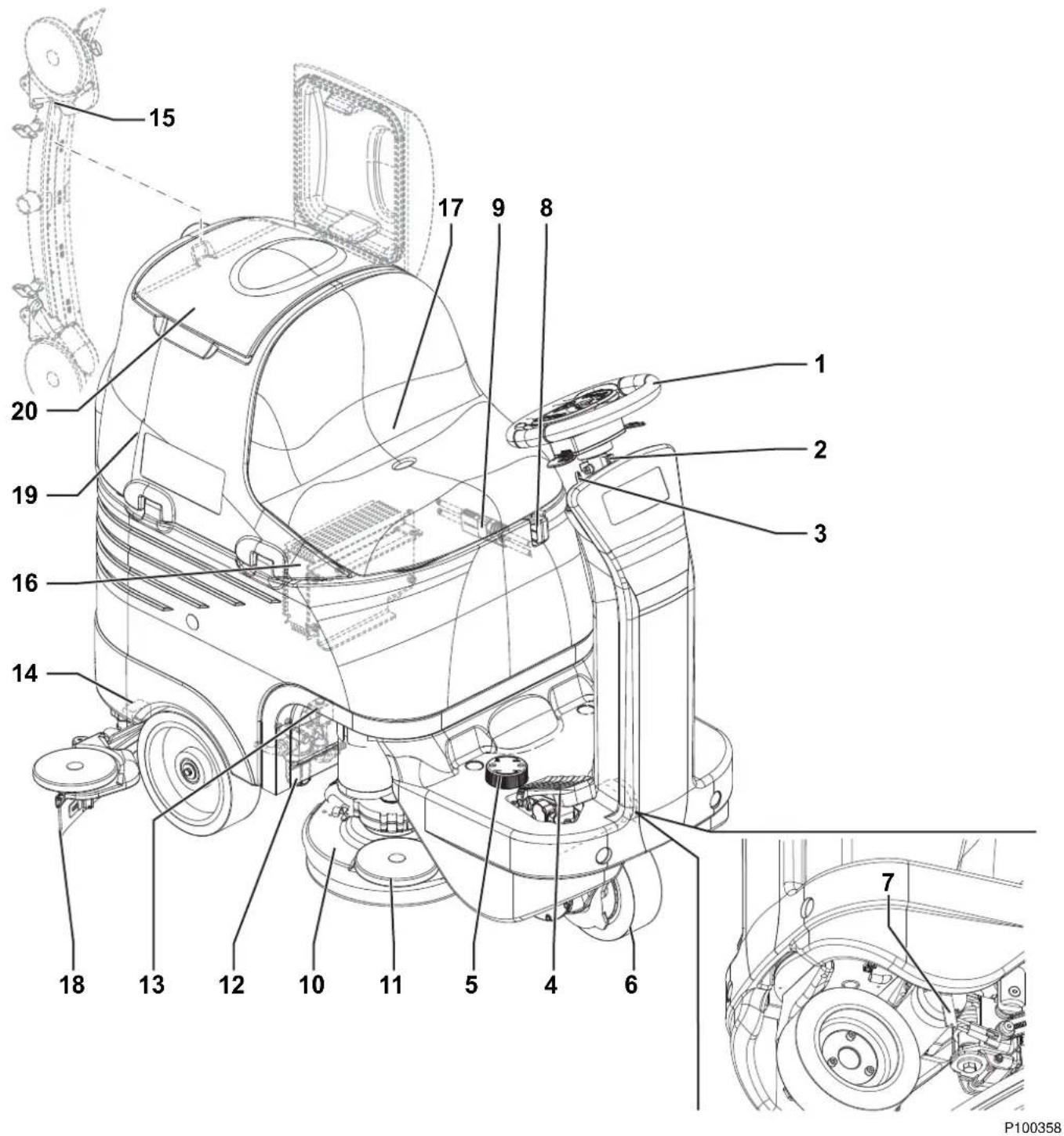
MACHINE STRUCTURE (Continues)
- Serial number plate/technical data/conformity certification Solution/clean water tank22.
- Solution/clean water tank filler plug with removable filler hose
Recovery water drain hose24.
Tank assembly stand25.
Container with debris collection grid26.
- Vacuum grid with automatic shut-off float Cylindrical brush deck28.
Cylindrical brush deck side skirt29.
Squeegee30.
Squeegee vacuum hose31.
- Squeegee bumper wheels
-
Squeegee support wheels
-
Squeegee mounting handwheels
- Squeegee balance adjusting handwheel
- Vacuum system motor
- Vacuum system motor filter
- Battery connection diagram
- Batteries
- Battery caps
- Battery charger cable
- Detergent tank (*)
- Electronic component compartment cover
- Lifted tank assembly and driver's seat
- Adapter for water removable filler hose and squeegee vacuum hose
- Solution/clean water tap
(*) Only for machine with EcoFlex™ system

P100359
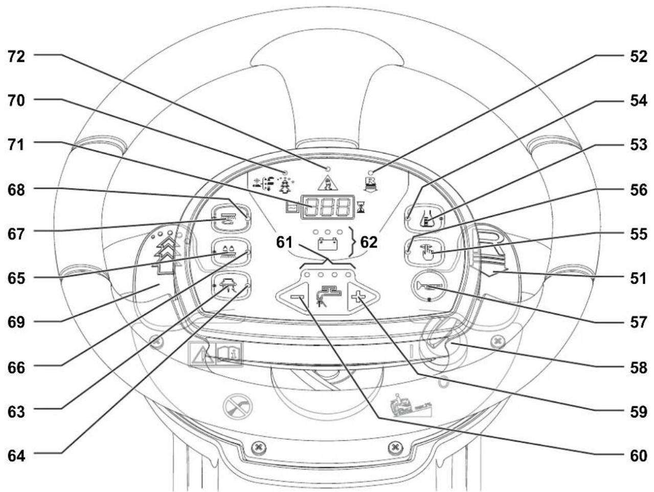
STEERING WHEEL WITH CONTROL PANEL
Reverse gear activation/deactivation lever51.
Reverse gear LED indicator52.
Detergent flow control switch (*)53.
Washing detergent flow control switch LED indicator (*)54.
Mute function switch55.
Mute function switch LED56.
Horn switch57.
Ignition key58.
Solution flow increase switch59.
- Battery warning lights
• Green warning light - charged battery
• Yellow warning light - semi-discharged battery
• Red warning light - discharged battery
-
Vacuum system switch
-
Vacuum system LED indicator
-
Extra pressure switch (the switch is enabled on 28" Cyl. version only)
-
Extra pressure LED indicator
-
Brush/pad-holder deck and squeegee lifting/lowering switch
-
Brush/pad-holder deck and squeegee lifting/lowering LED indicator
-
EcoFlex™ activation/deactivation lever (*)
-
EcoFlex™ system LED indicator (*):
• LED on - EcoFlex™ system on
• LED fl ashing - EcoFlex™ system override
• LED off - EcoFlex™ system disabled
- Hour counter and solution level display:
- When the machine is started, it displays for a few seconds the number of working hours which have been performed.
- While using the machine, it displays the solution/washing water level in the tank (in gallons).
- When the level is above 18 USgal, the display indicates "FUL".
- When the level is under 4 USgal, the display indicates "LO".
- When the tank is almost empty, "LO" starts flashing.

NOTE
The display could indicate "LO" even if the tank is not completely empty, thus allowing to complete the cleaning cycle; in any case, it is recommended to check the actual solution flow supplied to the brushes.
- Anti-skid control activation LED indicator
(*) Only for machines with EcoFlex™ system
P100360
ACCESSORIES/OPTIONS
In addition to the standard components, the machine can be equipped with the following accessories/options, according to the machine specific use:
GEL/AGM batteries –
Brushes and cylindrical brushes of different materials –
Pads of different materials –
Squeegee blades of different materials –
Flashing light –
Mop a trash kit –
0.9 HP (670 W) vacuum system motor -
For further information concerning the optional accessories, contact an authorized Retailer.
TECHNICAL DATA
General technical data
| Description 26” Disc 28” Cyl. | ||
| Cleaning width 26 in (660 mm) 28 in (710 mm) | ||
| Squeegee width | 35 in (890 mm) | |
| Solution/clean water tank capacity | 21 USgal (80 liters) | |
| Solution flow | 0.26 - 0.8 USgal/min (1 - 3 liters/min) | |
| Rear wheel diameter | 9.8 in (250 mm) | |
| Front wheel specific pressure on the floor | 72 psi (0.5 N/mm2) | |
| Rear wheel specific pressure on the floor | 130 psi (0.9 N/mm2) | |
| Front steering, driving and braking wheel diameter | 8.8 in (225 mm) | |
| Vacuum system motor power | 0.56 HP (420 W) | |
| Drive system motor power | 0.4 HP (300 W) | |
| Maximum speed | 3.7 mph (6 km/h) | |
| Maximum gradient when working 2% (1,14°) | ||
| Sound pressure level at workstation (ISO 11201, ISO 4871, EN 60335-2-72) (LpA) | 65 dB(A) ± 3 dB(A) | |
| Machine sound pressure level (ISO 3744, ISO 4871, EN 60335-2-72) (LwA) | 82 dB(A) | |
| Vibration level at the operator's arms (ISO 5349-1, EN 60335-2-72) | < 98,4 in/s2 (< 2.5 m/s2) | |
| Vibration level at the operator's body (ISO 2631-1, EN 60335-2-72) | 3.1 in/s2 (0.8 m/s2) | |
| Battery compartment size (length x width x height) | 14.9 x 21.2 x 11.8 in (380 x 540 x 300 mm) | |
| Battery type | 4 6 V batteries, 180 Ah C5 (WET) | |
| 4 6 V batteries, 180 Ah C5 (GEL/AGM) | ||
| Vacuum system capacity | 0.0098 MPa (1,000 mmH2O) | |
| Machine height | 46.8 in (1,190 mm) | |
| Machine maximum length | 53.5 in (1,360 mm) | |
| Machine width without squeegee | 26.4 in (670 mm) | 31.9 in (810 mm) |
Technical data for machines with brush/pad-holder deck
| Description | 26” Disc |
| Brush/pad diameter | 13 in (330 mm) |
| Weight without batteries and with empty tanks | 385.8 lb (175 kg) |
| Maximum weight with batteries, full tanks and operator (75 kg) (GVW) | 983.2 lb (446 kg) |
| Brush/pad motor power | 2 x 0.53 HP (2 x 400 W) |
| Brush/pad-holder speed | 230 rpm |
| Brush/pad-holder pressure with extra-pressure function turned off | 66.1 lb (30 kg) |
| Brush/pad-holder pressure with extra-pressure function turned on | 105.8 lb (48 kg) |
Technical data for machines with cylindrical brush deck
| Description 28” Cyl. | |
| Cylindrical brush size (diameter x length) 5.7 x 27.2 in (145 x 690 mm) | |
| Weight without batteries and with empty tanks 396.8 lb (180 kg) | |
| Maximum weight with batteries, full tanks and operator (75 kg) (GVW) 994.3 lb (451 kg) | |
| Cylindrical brush motor power 2 x 0.8 HP (2 x 600 W) | |
| Cylindrical brush speed 720 rpm | |
| Cylindrical brush pressure 77.1 lb (35 kg) |
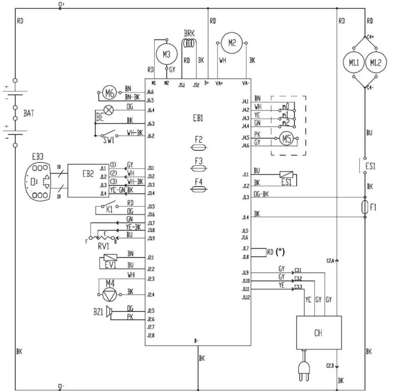
WIRING DIAGRAM
Key
| BAT 24 V battery box | |
| BE Flashing light (optional) | |
| BRK Electromagnetic brake | |
| BZ1 Reverse gear warning buzzer/horn | |
| C1 Battery connector | |
| C2 Battery charger main connector | |
| C3 Battery charger sub-connector | |
| C4 Brush deck connector | |
| CH Battery charger (optional) | |
| EB1 Function electronic board | |
| EB2 Display electronic board | |
| EB3 Dashboard instrument electronic board | |
| ES1 Brush electromagnetic switch | |
| EV1 Solenoid valve | |
| F1 Brush deck fuse | |
| F2 Main electronic board fuse | |
| F3 Signal circuit fuse | |
| F4 Actuator fuse | |
| K1 | Ignition switch |
| M1.1,2 | Brush motor |
| M2 | Vacuum system motor |
| M3 | Drive system motor |
| M4 | Detergent pump (optional) |
| M5 | Brush deck actuator motor |
| M6 | Squeegee actuator motor |
| m0 | Squeegee actuator position 0 microswitch |
| m1 | Squeegee actuator position 1 microswitch |
| m2 | Squeegee actuator position 2 microswitch |
| PR1 | Solution/clean water level pressure switch |
| RV1 | Drive pedal potentiometer |
| SW1 | Driver's seat microswitch |
Color codes
| BK Black | |
| BU | Blue |
| BN | Brown |
| GN | Green |
| GY Grey | |
| OG | Orange |
| PK Pink | |
| RD Red | |
| VT Violet | |
| WH | White |
| YE Yellow | |
(*) For SC3000 26" Disc version only
WIRING DIAGRAM (Continues)
P100361A
USE

WARNING!
On some points of the machine there are some adhesive plates indicating:
DANGER -
WARNING -
CAUTION –
CONSULTATION –
While reading this Manual, the operator must pay particular attention to the symbols shown on the plates. Do not cover these plates for any reason and immediately replace them if damaged.
BATTERY CHECK/SETTING ON A NEW MACHINE

WARNING!
The electric components of the machine can be seriously damaged if the batteries are either improperly installed or connected. The batteries must be installed by qualified personnel only. Set the function electronic board according to the type of batteries installed (WET or GEL/AGM).
Check the batteries for damage before installation.
Disconnect the battery connector and the battery charger plug.
Handle the batteries with great care.
Install the battery terminal protection caps supplied with the machine.
The machine requires 4 6 V batteries, connected according to the diagram (38).
The machine can be supplied in one of the following modes:
Batteries (WET or GEL/AGM) already installed and ready to be used
Open the cover (20) and check that the recovery tank (19) is empty, otherwise empty it with the drain hose (24).1.
Close the cover (20).2.
Carefully lift the tank assembly (44).3.
Check that the batteries are connected to the machine with the connector (9).4.
Carefully lower the tank assembly (44).5.
- Insert the ignition key (58) and turn it to "I". If the green warning light (62) turns on, the batteries are ready to be used. If the yellow or red warning light turns on, the batteries must be charged (see the procedure in Maintenance chapter).
Without batteries
-
Buy appropriate batteries (see the Technical Data paragraph).
For battery choice and installation, apply to qualified battery Retailers. -
Set the machine according to the type of batteries installed (WET or GEL/AGM) (see the following paragraph).
-
Install the batteries (see the following paragraph).
-
Charge the batteries.
BATTERY INSTALLATION AND BATTERY TYPE SETTING (WET OR GEL/AGM)
Battery installation
Open the cover (20) and check that the recovery tank (19) is empty, otherwise empty it with the drain hose (24).1.
Close the cover (20).2.
Carefully lift the tank assembly (44).3.
Install the batteries and connect them according to the diagram (38).4.
Battery type setting
Set the machine electronic board and the battery charger according to the type of batteries installed (WET or GEL/AGM) as shown below:
- Turn the ignition key (58) to "I" and, in the very first seconds of machine operation, detect the current setting by counting the number of flashes of the battery warning lights (62), as shown in the following table:
| SETTING DISPLAY (71) | BATTERY WARNING LIGHT INDICATION (62) | BATTERY TYPE CHARGING CURRENT | |
| 1 4 fl ashes | 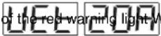 /ET /ET | STANDARD2 | |
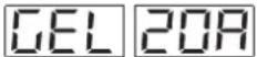 | 4 fl ashes of the green warning light GEL-AGM | ||
| 3 | 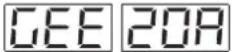 | 4 fl ashes of the yellow warning light GEL EXIDE ^ type | |
| 4 | 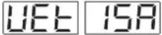 | 2 fl ashes of the red warning light WET | REDUCED (see note)5 |
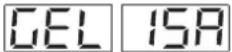 | 2 fl ashes of the green warning light GEL-AGM | ||
| 6 | 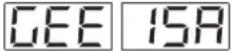 | 2 fl ashes of the yellow warning light GEL EXIDE ^ type | |
- If the setting is to be changed, perform the following procedure.
- Turn off the machine by turning the ignition key (58) to "0".
- Press and hold the switches (67) and (63) at the same time, then turn the ignition key (58) to "I".
- Release the switches (67) and (63) at least 5 seconds after starting the machine.
- Within 3 seconds, shortly press the switch (63) to go to the next setting (1 to 6 in cyclic sequence).

NOTE
When performing steps 9 and 10, the settings are shown on the display (71) too, by the code in the table.

NOTE
When using batteries with a capacity lower than 160Ah@5h (in case of doubt, refer to the battery documents), to avoid battery overheating during charging procedure, use the REDUCED charging current with setting 4, 5 or 6 shown in the table, according to the type of batteries installed.

NOTE
The battery charger must be set when setting the battery type.
Battery charging
- Charge the batteries (see the procedure in Maintenance chapter).
BEFORE START-UP

WARNING!
At every machine start-up, check that, between the deck (10 and 28) and the machine or between the squeegee (30) and the machine, there is no foreign material which may prevent the deck and the squeegee from lifting. This check is necessary because, if the machine has been turned off without lifting the deck and the squeegee, when turned on again, the deck and the squeegee lift automatically.
Brush/pad-holder installation/removal
(For SC3000 26" Disc)
According to the kind of cleaning to be performed, the machine can be equipped either with brushes (A, Fig. 1) or pad-holders (B) with pads (C) together with the appropriate deck.
For the installation/removal, proceed as follows.
Insert the ignition key (58) and turn it to "I".1.

WARNING!
Before pressing the switch (67), always check that, between the deck (10) and the machine there is no foreign material which may prevent the deck from lifting.
Lift the deck by pressing the switch (67).2.
Turn the ignition key (58) to "0" and remove it.3.
- Install the brushes/pad-holders (A or B) in the drive hub (D) under the deck, then turn them in the opposite direction to their rotation direction, until they reach the end of stroke (E).
- To remove the brushes/pad-holders perform steps 1 to 3, then manually release the brush/pad-holder from the hub by turning it abruptly in its normal rotation direction (F).

WARNING!
If the machine is not perfectly assembled it can cause damages to people and properties. Always check that all components are assembled before starting the machine. Carefully inspect the machine before using it.
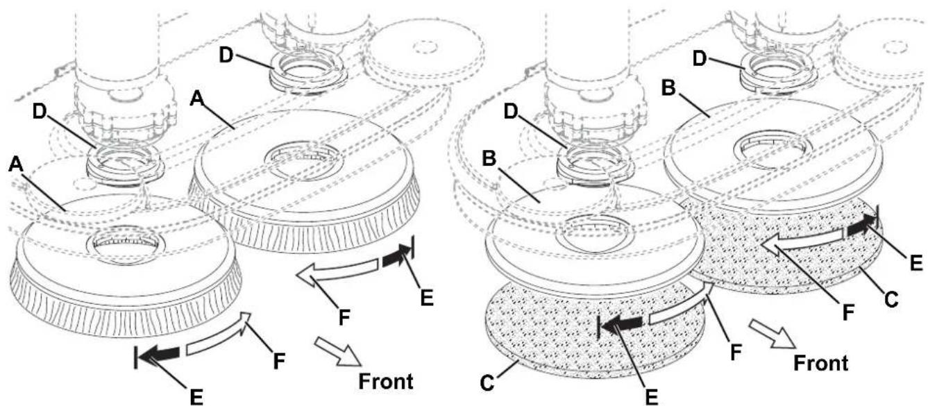
Figure 1
P100362
Available brushes and their relevant application guides (suggestions only)
| Models MIDLITE GRIT 180 MIDGRIT 240 PROLENE PROLITE UNION MIX | |||||
| General cleaning: | |||||
| Concrete | |||||
| Terrazzo il oor | |||||
| Ceramic tiles/quarrystones | |||||
| Marble | |||||
| Vinyl tiles | |||||
| Rubber tiles | |||||
| Polishing: | |||||
| Rubber tiles | |||||
| Marble | |||||
| Vinyl tiles | |||||
Cylindrical brush installation/removal
(For SC3000 28" Cyl.)
Insert the ignition key (58) and turn it to "I".1.

WARNING!
Before pressing the switch (67), always check that, between the deck (28) and the machine there is no foreign material which may prevent the deck from lifting.
Lift the deck by pressing the switch (67).2.
Turn the ignition key (58) to "0" and remove it.3.
On both sides of the machine, unscrew the knobs (A, Fig. 2) and remove the side skirt assemblies (B).4.
Unscrew the knobs (C) and remove the lids (D) by pushing the knobs downwards.5.
Install the cylindrical brushes (E), or remove them to install new ones.6.
The cylindrical brushes must be installed on either sides.
Install the lids (D) and fasten them with the knobs (C).7
- Install the side skirt assemblies (B) and fasten them with the knobs (A).

WARNING!
If the machine is not perfectly assembled it can cause damages to people and properties. Always check that all components are assembled before starting the machine. Carefully inspect the machine before using it.
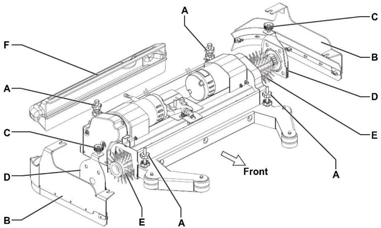
Figure 2
P100363
Available cylindrical brushes and their relevant application guides (suggestions only)
| Models MAGNA GRIT 46 DYNA GRIT | 80 MIDLITE GRIT | 180 PROLENE PROLITE UNION MIX | |||
| General cleaning: | |||||
| Concrete | |||||
| Terrazzo floor | |||||
| Ceramic tiles/quarrystones | |||||
| Marble | |||||
| Vinyl tiles | |||||
| Rubber tiles | |||||
Squeegee installation
Install the squeegee (30) and fasten it with the handwheels (34), then connect the vacuum hose (31) to the squeegee.1.
- With the handwheel (35), adjust the squeegee so that the rear blades (18) - in all its length - touches the floor and the front blade is slightly detached from the floor.
Solution/clean water tank fi lling

NOTE
If the machine is equipped with EcoFlex™ system pour clean water in the tank, otherwise pour solution.

CAUTION!
Use only low-foam and non-flammable detergents, intended for automatic scrubber applications.

WARNING!
When using floor cleaning detergents, follow the instructions on the labels of the detergent bottles.
To handle floor cleaning detergents, wear suitable gloves and protections.
Open the plug (23).1.
(For machine without EcoFlex™ system)2.
Use the removable filler hose to fill the tank (22) with a solution suitable for the work to be performed.
Do not fill the tank (22) completely, leave a few inches from the edge of the plug (23).
Always follow the dilution instructions on the label of the chemical product used to prepare the solution.
The solution temperature must not exceed 40 °C.
(For machine with EcoFlex™ system)
Fill the tank (22) with clean water by using the removable filler hose.
Do not fill the tank (22) completely, leave a few inches from the edge of the plug (23).
The water temperature must not exceed 40 °C.
Detergent tank fi lling
(For machine with EcoFlex™ system)
-
Open the cover (20) and check that the recovery tank (19) is empty, otherwise empty it with the drain hose (23).
-
Close the cover (20).
-
Carefully lift the tank assembly (44).
-
Open the detergent tank plug (42).
-
Fill the tank with a detergent suitable for the work to be performed (highly concentrated detergent).
Do not fill the detergent tank completely, leave a few inches from the edge.

NOTE
If the detergent tank is empty (in case of new system, system emptied for cleaning, etc.), in order to fill the hose quickly, it may be useful to drain EcoFlex™ system once or several times (see the procedure in Maintenance chapter).
Operator's position adjustment
- Adjust the height of the steering wheel (1) with the lever (2) and the height of the heel support (5) to reach a comfortable position.
MACHINE START AND STOP
Starting the machine
Prepare the machine as shown in the previous paragraph.1.
- Turn the ignition key (58) to "I" without pressing the drive pedal (4). Check if the battery green warning light (62) turns on. If the yellow or red warning light turns on, turn the ignition key (58) back to "0" and charge the batteries (see the procedure in Maintenance chapter).
Drive the machine to the working place by keeping the hands on the steering wheel and pressing the pedal (4).3.
The drive speed can be adjusted from zero to maximum speed by increasing the pressure on the pedal (4).
The forward/reverse gear is selected with the relevant lever (51) which is at the right of the steering wheel.4.

NOTE
The driver's seat (17) is equipped with a safety sensor, which allows the machine to be driven by pressing the pedal (4) only when the operator is on the driver's seat.

NOTE
The machine is equipped with an anti-skid safety system (LED (72) flashing) that reduces the speed when turning and when the machine tilts laterally, irrespectively of the pressure on the pedal.
In this case, the reduction of speed is not a malfunction but a characteristic that improves the machine stability and safety in every condition.
Lower the brush/pad-holder deck and the squeegee by pressing the switch (67).5.
- Press the solution flow control switches (59 and 60) according to the type of cleaning to be performed.
Start scrubbing, by turning the steering wheel (1) and moving the machine forward by pressing the pedal (4).7.

NOTE
The machine is equipped with a safety system that turns on the brushes and vacuum system only when the machine is moving.
Stopping the machine
Release the pedal (4).8.
It is not necessary to lock the machine during stopping or parking, because the electromagnetic brake on the wheel turns on automatically when the drive pedal is not pressed.
Lift the brush/pad-holder deck and the squeegee by pressing the switch (67).9.
MACHINE OPERATION (SCRUBBING/DRYING)
Start the machine as shown in the previous paragraph.1.
If necessary, adjust the solution quantity by pressing the switches (59 and 60).2.
If necessary, to reduce the noise, turn on the mute function by pressing the switch (55).3.

NOTE
It is suggested to use the mute function only on smooth floors without joints.

NOTE
For correct scrubbing/drying of floors at the sides of the walls, Advance suggests to go near the walls with the right side of the machine as shown in figure 3.
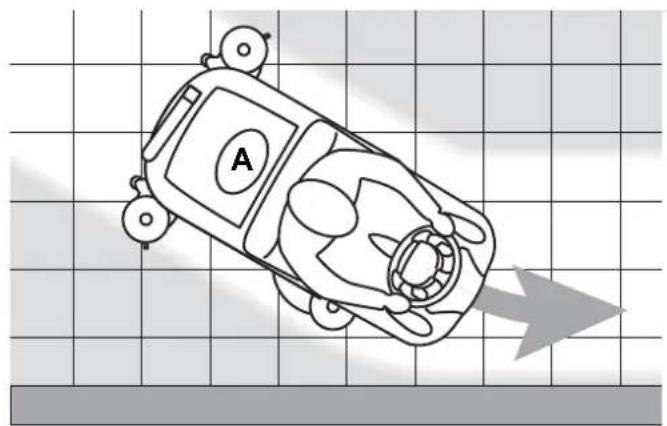
natural_image
Top-down line drawing of a car with a labeled section 'A' on a grid background, no text or symbols present.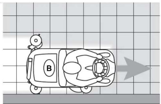
natural_image
Top-down line drawing of a cartoon car with a small robot and labeled 'B' on the front, set against a grid background with an arrow (no text or symbols beyond labels)Figure 3
P100364
Squeegee adjustment
- If necessary, stop the machine and turn the squeegee balance adjusting handwheel (35) so that the rear blade - in all its length - touches the floor.
Adjustment of the detergent concentration in the solution
(For machine with EcoFlex™ system)
The system used to mix the detergent with the washing water can be activated by pressing the detergent flow control switch (A, Fig. 4): when the LED (B) is on, the detergent is added to the washing water.
The display (C) shows the detergent concentration level in the solution as shown in the table in Figure 5.

NOTE
The detergent concentration in the solution dispensed from the system always corresponds to level 1. In order to temporarily obtain a stronger concentration, press the EcoFlex ^TM switch or disable the EcoFlex ^TM system (see the relevant paragraph).
EcoFlex™ function
Lift the EcoFlex™ lever (D, Fig. 4) whenever a stronger washing power is required.
When lifting the lever (D) (LED (E) flashing) the solution flow increases, the extra pressure function activates (for machines with EcoFlex™ system) and the detergent concentration in the corresponding solution rises to the set level (moreover, if the detergent mixing function is not activated, it activates automatically).
The original settings can be restored by lifting the lever (D) once again (LED (F) on).

NOTE
If the lever (D) is not lifted once again, the original settings are restored automatically after 60 seconds.
In order to change the actual detergent concentration, proceed as follows:
- Turn off the detergent flow control switch (A) (the LED (B) must be OFF).
- Press and hold the detergent flow control switch (A) until the LED (B) flashes.
- Release the switch (A). Press it again shortly to go to the next level shown by the display (C) as shown in the table in Figure 4; repeat the procedure until the desired setting is reached.
Wait until the LED (B) stops fl ashing: the new level is now set.4.

NOTE
Detergent percentage setting is stored into memory, even if the machine is turned off.
EcoFlex™ system disabling procedure
(For machine with EcoFlex™ system)
In order to temporarily disable the system, lift the EcoFlex™ lever (D, Fig. 4) and keep it lifted for 2 seconds.
After this procedure, (LED (D) off), the detergent concentration level is the one which has been set.
To enable the system, lift the EcoFlex ^TM lever (D) again.
In order to permanently disable the EcoFlex™ system, proceed as follows:
Turn off the machine by turning the ignition key (58) to "0".1.
Lift the lever (D), then turn the ignition key (58) to "I".2.
Release the lever (D) at least 8 seconds after turning on the machine.3.
After this procedure, the EcoFlex™ lever cannot be operated again (LED (E) off) and the detergent concentration level is the one which has been set.
In order to re-enable the system, repeat the steps 1 to 3.

NOTE
The permanent disabling of the EcoFlex ^TM system is stored into memory even after the machine is turned off.
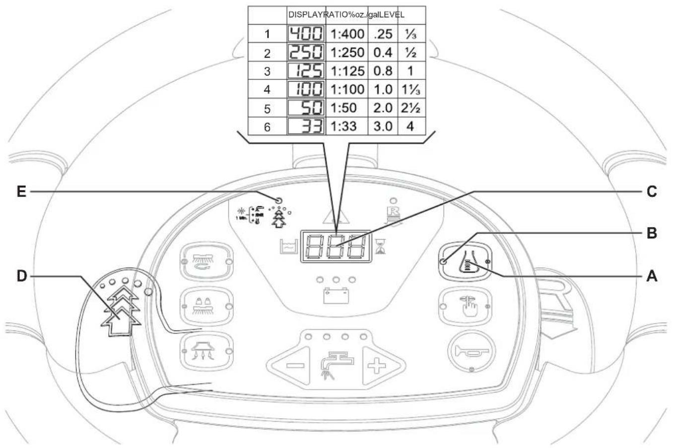
Figure 4
P100365A
Working with brush/pad-holder extra pressure function activated (only for SC3000 26" Disc)
- If the floor proves to be particularly difficult to clean, it is possible to turn on the brush/pad-holder extra pressure function by pressing the switch (65).
To return to normal pressure, press the switch (65) again.2.
The switch (65) is enabled only when the deck (10) is lowered and the LED (68) of the switch (67) is on.

CAUTION!
In case of brush/pad-holder motor overload, due to foreign bodies which prevent them from turning, or to excessively aggressive floors/brushes, the safety system stops the brushes/pad-holders after about one minute of continuous overload.
The overload is shown by the three battery warning lights (62) flashing simultaneously.
If the overload takes place when the extra pressure function is on, the system automatically reduces the pressure on the brushes/pad-holders, thus turning the extra pressure function off. If the overload persists, the brushes/pad-holders stop.
To start scrubbing again after a brush/pad-holder stop due to overload, stop the machine by turning the ignition key (58) to "0". Turn on the machine by turning the ignition key (58) to "1".
Battery discharge during operation
Until the green warning light (62) stays on, the batteries allow the machine to work normally.1.
When the green warning light turns off and first the yellow warning light then the red warning light turn on, the batteries must be charged.
When the yellow warning light turns on the machine residual autonomy will last for a few minutes (depending on the characteristics of the battery).
When the red warning light turns on the machine autonomy is over: after a few seconds the brushes/pad-holders are • automatically stopped and the deck is automatically lifted. Only vacuum and drive systems still operate, just to dry the wet floor and move the machine to the appointed charging area.

CAUTION!
Do not use the machine with discharged batteries, to avoid damaging the batteries and reducing the battery life.

NOTE
In case the machine drive system cannot be used in order to move the machine, see Pushing/Towing The Machine paragraph.
TANK EMPTYING
An automatic float shut-off system (27) turns off the vacuum system when the recovery tank (19) is full.
The vacuum system deactivation is signaled by a sudden increase in the vacuum system motor noise frequency, also the floor has not dried.

CAUTION!
If the vacuum system turns off accidentally (for example, when the float is activated because of a sudden machine movement), to resume the operation: turn off the vacuum system by pressing the switch (63), then open the cover (20) and check that the float inside the grid (27) has gone down to the water level. Then close the cover (20) and turn on the vacuum system by pressing the switch (63).
When the recovery tank (19) is full, empty it according to the following procedure.
Recovery tank emptying
Stop the machine by releasing the pedal (4).1.
Lift the brush/pad-holder deck and the squeegee by pressing the switch (67).2.
Drive the machine to the appointed disposal area.3.
Empty the recovery tank with the hose (24).4.
-
Remove the container with debris collection grid (26), empty it and clean it with clean water. Then install it on the suction hose in the tank.
-
Then, rinse the tank with clean water.
Solution/clean water tank emptying
Perform steps 1 to 3.7.
Remove the adapter (45) from its housing inside the battery compartment.8.
Install the adapter (A, Fig. 5) on the squeegee vacuum hose (B), then fasten it to the drain valve (C).9.
Turn the ignition key (58) to "I" and turn on the vacuum system with the switch (63).10.
Open the drain valve (C) to drain the tank (22).11.
The valve (C) is open when it is in the position (D) and it is closed when it is in the position (E).
Then, turn of the vacuum system and drain the recovery tank (19) with the hose (24). 12.
- When the procedure is over, close the drain valve (C), remove the adapter (A) and install the vacuum hose (B) on the squeegee (30).
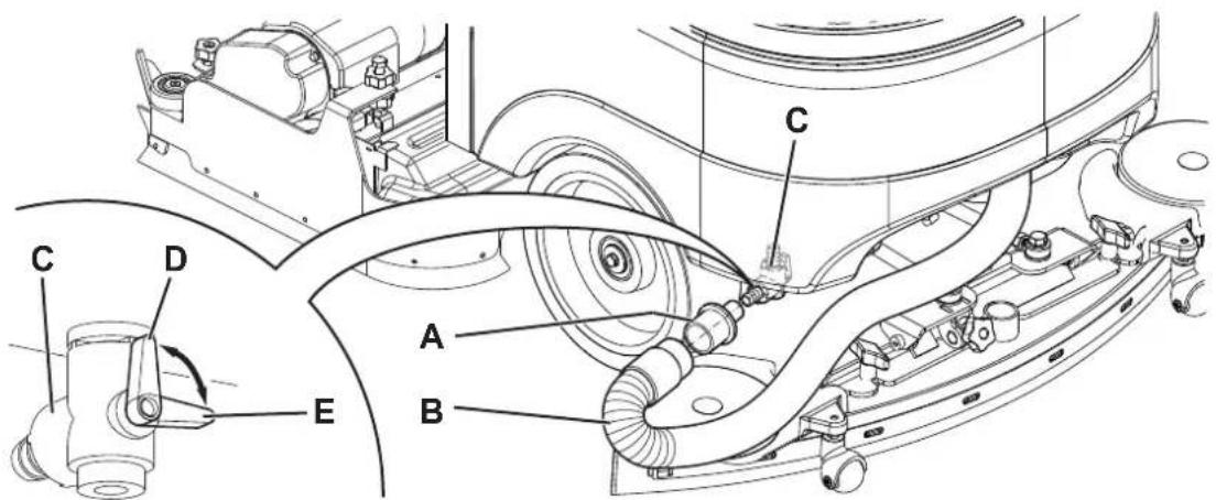
Figure 5
P100366
Cylindrical brush debris container emptying (only for cylindrical brush deck)
Stop the machine.14.
Lower the cylindrical brush deck and remove the debris container (F, Fig. 2).15.
Empty and wash the debris container (F), and then install it on the relevant stand.16.
AFTER USING THE MACHINE
After working, before leaving the machine:
Remove the brushes/pad-holders as shown in the relevant paragraph.1.
- Empty the tanks (19 and 22) as shown in the previous paragraph.
- Remove the squeegee (30) and clean it with hot water. Open the recovery tank cover (20) and hang the squeegee on the recovery tank by using the relevant hook (15).
- Perform the daily maintenance procedures (see the Maintenance chapter).
- Store the machine in a clean and dry place, with the brushes/pad-holders and the squeegee lifted or removed.
To push/tow the machine easily when the drive system cannot be used (for example in case of missing batteries, discharged batteries, etc.), disengage the electromagnetic brake by pulling the lever (7) and locking it with a spacer.
When the operation is over, remove the spacer under the lever (7) to activate the electromagnetic brake again.

WARNING!
If the lever (7) is not disengaged after pushing/towing the machine, the electromagnetic brake is disengaged.

WARNING!
Do not start the machine when the electromagnetic brake is disengaged.
For safety reasons, it is recommended to disengage the electromagnetic brake only for the time necessary to manually move the machine.
MACHINE LONG INACTIVITY
- If the machine is not going to be used for more than 30 days, proceed as follows:
- Perform the procedures shown in After using the machine paragraph.
- Before disconnecting the battery red connector (9), proceed as follows:
- Open the cover (20) and the plug (23), then check that the tanks (19 and 22) are empty, otherwise empty them.
- Keep the recovery tank assembly (19) lifted by using the stand (25).
FIRST PERIOD OF USE
After the first 8 hours, check the machine fastening and connecting parts for proper tightening. Check the visible parts for integrity and leakage.
MAINTENANCE
The lifespan of the machine and its maximum operating safety are ensured by correct and regular maintenance.
The following chart provides the scheduled maintenance. The intervals shown may vary according to particular working conditions, which are to be defined by the person in charge of the maintenance.

WARNING!
The procedures must be performed with the machine off and the battery disconnected.
Moreover, carefully read the instructions in the Safety chapter.
All scheduled or extraordinary maintenance procedures must be performed by qualified personnel, or by an authorized Service Center.
This Manual describes only the easiest and most common maintenance procedures.

NOTE
For other maintenance procedures shown in the Scheduled Maintenance Table, refer to the Service Manual that can be consulted at any Service Center.
SCHEDULED MAINTENANCE TABLE
| Procedure | Daily, after using the machine | Weekly | Every six months | Yearly |
| Battery charging | ||||
| Squeegee cleaning | ||||
| Brush/pad cleaning | ||||
| Tank, debris collection grid and vacuum grid with float cleaning, and cover gasket check | ||||
| EcoFlexTM system cleaning and draining | ||||
| Squeegee blade check and replacement | ||||
| Side skirt check (only for 28" Cyl.) | ||||
| Solution filter cleaning | ||||
| Vacuum system motor filter cleaning | ||||
| Battery (WET) fluid level check | ||||
| Screw and nut tightening check (1) | ||||
| Check and adjustment of driving belts between motors and cylindrical brushes (only for 28" Cyl.) | (2) | |||
| Electromagnetic brake efficiency check | (2) | |||
| Brush/pad-holder motor carbon brush check or replacement (2) | ||||
| Vacuum system motor carbon brush check or replacement (2) | ||||
| Drive system motor carbon brush check or replacement (2) |
And after the first 8 working hours.(1)
This maintenance procedure must be performed by a Advance authorized Service Center.(2)
MACHINE WORKING HOUR CHECK
Insert the ignition key (58) and turn it to "I".1.
- In the first 2 seconds of machine operation, the display (71) shows the total number of working hours (scrubbing/drying) performed by the machine.
Turn the ignition key (58) to "0".
SQUEEGEE CLEANING

NOTE
The squeegee must be clean and its blades must be in good conditions in order to get a good drying.

CAUTION!
It is advisable to wear protective gloves when cleaning the squeegee because there may be sharp debris.
Drive the machine on a level floor.1.
Insert the ignition key (58) and turn it to "I".2.
Lower the squeegee (30) by pressing the switch (63).3.
Turn the ignition key (58) to "0".4.
Disconnect the vacuum hose (31) from the squeegee.5.
Loosen the handwheels (34) and remove the squeegee (30).6.
- Wash and clean the squeegee. In particular, remove dirt and debris from the compartments (A, Fig. 6) and the hole (B). Check that the front blade (C) and the rear blade (D) are integral and free from cuts and lacerations; if necessary replace them. Assemble in the reverse order of disassembly.8.
SQUEEGEE BLADE CHECK AND REPLACEMENT
Clean the squeegee (Fig. 6) as shown in the previous paragraph.1.
- Check that the edge (E) of the front blade (C) and the edge (F) of the rear blade (D) lay down on the same level, along their length; otherwise adjust their height according to the following procedure:
- Remove the tie rod (G), disengage the fastener (M) and adjust the rear blade (D); then engage the fastener and install the tie rod.
Loosen the handwheels (I) and adjust the front blade (C), then tighten the handwheels.
-
Check the front blade (C) and rear blade (D) for integrity, cuts and tears; otherwise replace them according to the following procedure. Check the front corner (J) of the rear blade for wear; if necessary, overturn the blade to replace the worn corner with an integral one. If the other corners are worn too, replace the blade according to the following procedure:
-
Remove the tie rod (G), disengage the fastener (M) and remove the retaining strip (K), then replace/overturn the rear blade (D).
• Install the blade in the reverse order of removal. - Unscrew the handwheels (I) and remove the retaining strip (L), then replace the front blade (C).
• Install the blade in the reverse order of removal.
After the blade replacement (or overturning), adjust the height as shown in the previous step.
- Connect the vacuum hose (31) to the squeegee.
- Install the squeegee (30) and screw down the handwheels (34).
- If necessary, adjust the squeegee balance adjusting handwheel (35).
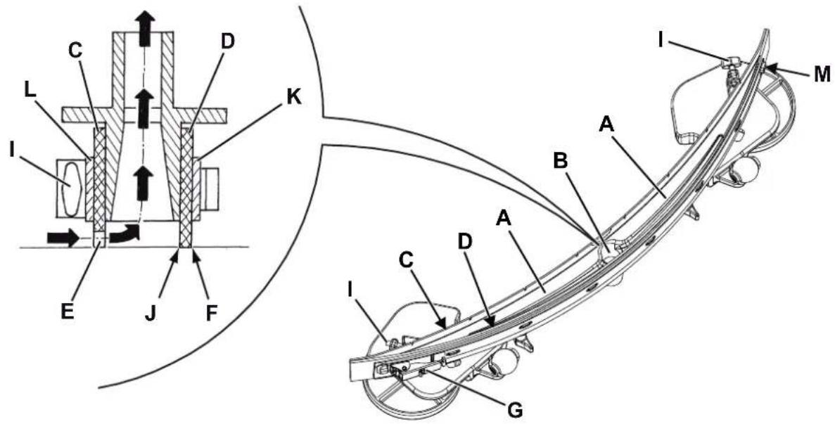
Figure 6
P100367
BRUSH/CYLINDRICAL BRUSH CLEANING

CAUTION!
It is advisable to wear protective gloves when cleaning the brushes because there may be sharp debris.
Remove the brushes/pads from the machine, as shown in Use chapter.1.
Clean and wash the brushes with water and detergent.2.
Check the brush bristles for integrity and wear; if necessary, replace the brushes.3.
RECOVERY TANK CLEANING
Drive the machine to the appointed disposal area.1.
Turn the ignition key (58) to "0".2.
Open the cover (20).3.
Clean and wash with clean water the cover (20) and the tank (19).4.
Drain the water in the tank through the hose (24).
-
Clean the vacuum grid (27), release the fasteners (A, Fig. 7), open the grid (B) and recover the float (C) then clean carefully and reinstall.
-
Clean the container with debris collection grid (26), remove the container (G), remove the cover (H), then clean carefully and reinstall the vacuum hose.
Check the tank cover gasket (D) for integrity.7.

NOTE
The gasket (D) creates vacuum in the tank that is necessary for the vacuuming of recovery water.
If necessary replace the gasket (D) by removing it from its housing (E). When assembling the new gasket, install the joint (F) in the lower area, as shown in the figure.
Check that the seating surface (I) of the gasket (D) is integral, clean and adequate for the gasket itself.7.
Close the cover (20).8.
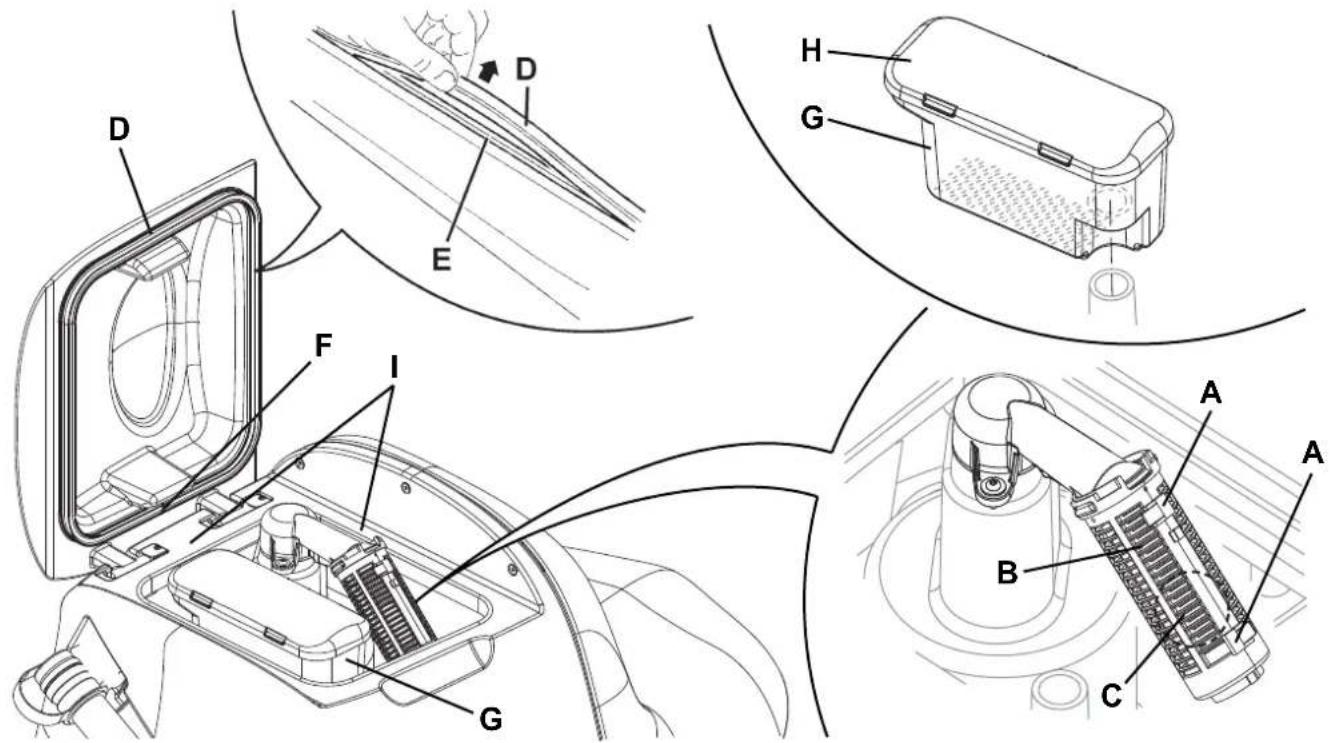
Figure 8
P100368
SIDE SKIRT CHECK AND REPLACEMENT (only for 28" Cyl.)
Check
Drive the machine on a level floor.1.
Turn the ignition key (58) to "0".2.
On both sides of the machine, unscrew the knob (A, Fig. 8) and remove the side skirt assemblies (B).3.
Wash and clean the skirt.4.
Check that the skirt lower edge (C):5.
lays down on the same level, along all its length;
is integral and free from cuts and lacerations;
has the inner corner (D) that is not worn;
Otherwise overturn or replace the skirts according to the following procedure.
Overturning or replacement
Remove the wing nuts (E), then remove the retaining strip (F).6.
- Remove the skirt blade (G) and, if possible, overturn the blade to replace the lower inner corner (D) with an integral one. If the other three corners are worn too, replace the blade.
Assembly and height adjustment
Assemble the blades (G) and skirt assembly (B) in the reverse order of disassembly.8.
Start the machine and lower the cylindrical brush deck (28), then check that the side skirt blades (G):9.
• slightly touch the floor;
• collect the solution.
-
If necessary stop the machine and adjust the skirt height by loosening the knob (A) and turning the knobs (H).
-
After adjusting, tighten the knob (A).
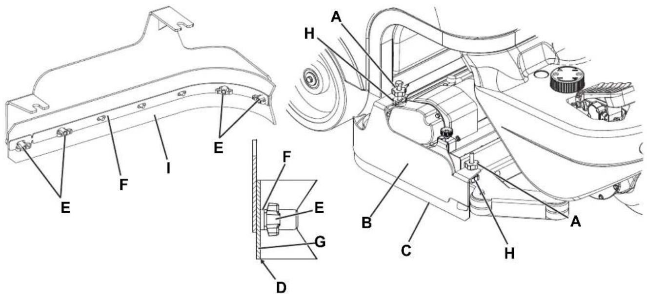
Figure 8
P100369
VACUUM SYSTEM MOTOR FILTER CLEANING
Drive the machine on a level floor.1.
Turn the ignition key (58) to "0".2.
Open the cover (20) and check that the recovery tank (19) is empty, otherwise empty it with the drain hose (24).3.
Close the cover (20).4.
Carefully lift the tank assembly (44). 5.
- Check that the filter (37) is clean. If necessary clean it with water and compressed air, then install it.
SOLUTION FILTER CLEANING
Drive the machine on a level floor.1.
Turn the ignition key (58) to "0".2.
-
Close the solution valve (A, Fig. 9) under the machine, behind the right rear wheel. The valve (A) is closed when it is in the position (B) and it is open when it is in the position (C).
-
Remove the transparent cup (D), recover the gasket (E), then remove the filter strainer (F) under the machine, in front of the right rear wheel. Clean them with water and install them on the support (G).

NOTE
The filter strainer (F) must be correctly positioned on the housing of the support (G).
Open the valve (A).5.
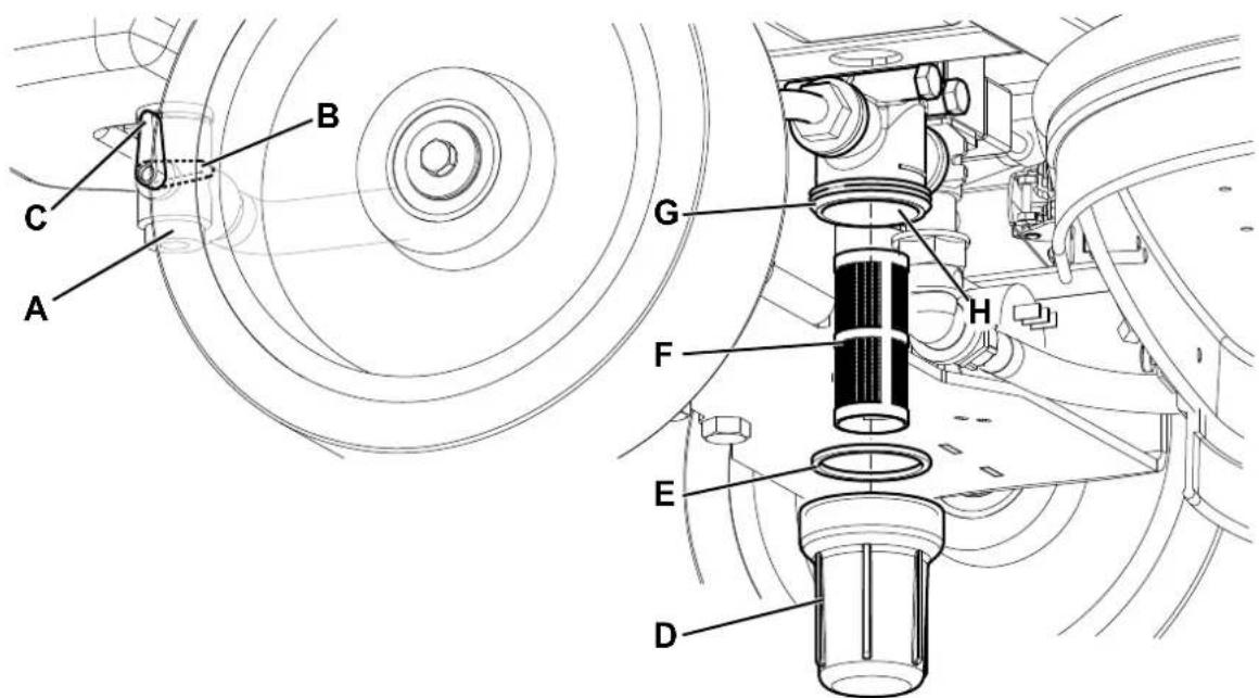
Figure 9
P100370
BATTERY CHARGING

NOTE
Charge the batteries when the yellow or red warning light (62) turns on, or at the end of every working cycle.

CAUTION!
Keeping the batteries charged make them last longer.

CAUTION!
When the batteries are discharged, charge them as soon as possible, as that condition makes their life shorter.
Check for battery charge at least once a week.

WARNING!
Battery charging produces highly explosive hydrogen gas. Charge the batteries in well-ventilated areas and away from naked ames.
Do not smoke while charging the batteries.
While charging the battery, always keep the tank assembly open with the relevant stand (25).

WARNING!
Pay careful attention when charging the batteries as there may be battery fluid leakages. The battery fluid is corrosive. If it comes in contact with skin or eyes, rinse thoroughly with water and consult a physician.
Preliminary procedures
Drive the machine on a level floor.1.
Open the cover (20) and check that the tank (19) is empty, otherwise empty it with the drain hose (24).2.
Close the cover (20).3.
Carefully lift the tank assembly (44).4.
- (For WET batteries only) Check the level of electrolyte inside the batteries (39). If necessary, unscrew the plugs (40) and top up.
When the correct level is reached, close the caps (40) and, if necessary, clean the upper surface of the batteries.
Battery charging
- Connect the battery charger cable (41) to the electrical mains (the electrical mains voltage and frequency must be compatible with the battery charger values shown on the machine serial number plate).

NOTE
When the battery charger is connected to the electrical mains, all machine functions are automatically cut off.
The red warning light (62) is on when the battery charger is charging the batteries.
The yellow warning light (62) is on when the battery charger is completing the battery charging.
When the green warning light turns on, the battery charging is completed.4.
- When the battery charging is completed, disconnect the battery charger cable (41) from the electrical mains and wind it round its housing behind the battery charger.
Carefully lower the tank assembly (44). 6.
Now the machine is ready to be used.7.

NOTE
For further information about the battery charger operation (16), see the relevant Manual.
DETERGENT TANK CLEANING
(For machine with EcoFlex™ system)
Clean the detergent tank (42) according to the following procedure:
Drive the machine to the appointed disposal area.1.
- Open the cover (20) and check that the recovery tank (19) is empty, otherwise empty it with the drain hose (24). Close the cover (20).
Carefully lift the tank assembly (44).3.
Unscrew the plug and disconnect the hose (A, Fig. 10) from the tank (B).4.
Remove the tank.5.
Wash the tank in the appointed disposal area.6.
-
Install the tank (42) in the position shown in the figure and connect it to the hose (A).
-
When the detergent tank has been drained, the EcoFlex™ system must be drained too (see the procedure in the following paragraph).
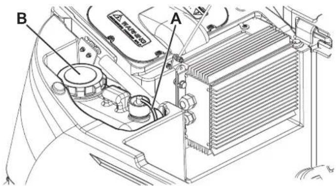
Figure 10
P100371
(For machine with EcoFlex™ system)
- Clean the detergent tank according to the procedure shown in the previous paragraph. To remove the detergent remained in the hoses and in the pump, perform the following procedure.
Turn on the machine by turning the ignition key (58) to "I" position.2.
-
Press the switch (53). Check that the switch LED (54) turns on.
-
Press the switches (53 and 59) at the same time, until the switch LED (54) starts flashing (after about 5 seconds).
-
Release the switches and wait for the LED (54) to stop flashing and for the vacuum system to turn on.
-
Collect the detergent remained on the floor.
-
Turn the ignition key (58) to "0".
-
Lift the tank (19), then check that the detergent tank hose (42) is empty, otherwise perform steps 3 to 7 again.

NOTE
The draining cycle lasts about 30 seconds, then the vacuum function automatically turns on, which allows to remove the detergent remained.
The draining cycle can also be performed with the detergent tank (42) full of water, thus cleaning the system thoroughly. It is advisable to perform this type of draining to clean the EcoFlex ^™ system from dirt and deposits if the machine has not been used/cleaned for a long time.
The draining cycle can be performed also to quickly fill the detergent supply hose when the tank (42) is full but the system is still empty.
If necessary, the draining cycle can be repeatedly performed.
FUSE CHECK/REPLACEMENT

NOTE
All machine electrical circuits are protected by auto-resettable electronic devices. The safety fuses activates only in case of serious damage.
It is recommended to have the fuses replaced by qualified personnel only.
Refer to the Service Manual available at any Advance Retailer.
SAFETY FUNCTIONS
The machine is equipped with the following safety functions.
EMERGENCY PUSH-BUTTON
It is located in an easily accessible position (8). Press it firmly in case of immediate necessity to stop all machine functions.
To reset the machine operation, lift the tank assembly (44) and reconnect the battery connector (9).
ANTI-SKID SAFETY SYSTEM
This system reduces the speed when turning and when the machine tilts laterally to avoid sudden skids, this increasing the machine stability in any condition.
DRIVER'S SEAT MICROSWITCH
It is located inside the driver's seat and it does not allow the machine drive system to operate if the operator is not seated on the driver's seat.
ELECTROMAGNETIC BRAKE
It is built-in the front wheel and keeps the machine braked when the machine is off or stopped.
TROUBLESHOOTING
| TROUBLE POSSIBLE CAUSE | REMEDY | |
| The motors do not work; no warning light turns on. | The battery connector is disconnected. Connect. | |
| The batteries are discharged. Charge the batteries. | ||
The machine does not move and the display (71) shows the error code: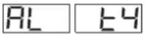 | The machine has been turned on by using the ignition key and by keeping the pedal pressed. | Release the drive pedal.If the problem persists, contact an authorised Service Center. |
| At the machine start-up, the LED (68) of the switch (67) ashes and the brushes do not work. | The machine has been turned off without lifting the brush deck. | Wait for the deck to lift before turning on again the brushes by pressing the switch. |
| The brushes do not work; the red warning light ashes. | The batteries are discharged. Charge the batteries. | |
| The 3 warning lights (62) flash simultaneously. | The brush motors are overloaded. | Use less aggressive brushes and/or avoid working with extra pressure turned on. |
| There are foreign materials (tangled threads, etc.) preventing the brushes from rotating. | Clean the brush hubs. | |
The display (71) shows an error code as: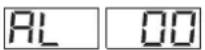 where “00” is replaced by a code different from “t4”. where “00” is replaced by a code different from “t4”. | The machine electronic control system is in alarm condition. | Turn off the machine and then turn it on again.If the problem persists, contact an authorised Service Center. |
| The dirty water vacuuming is insufficient. | The recovery tank is full. | Empty the tank. |
| The vacuum grid is clogged or the oil oat is closing. | Clean the vacuum grid. | |
| The container with debris collection grid is clogged. | Clean. | |
| The hose is disconnected from the squeegee connect. | ||
| The squeegee is dirty, or the squeegee blades are worn or damaged. | Clean the squeegee or overturn/replace the blades. | |
| The tank cover is not properly closed, or the gasket is damaged. | Correctly close the cover or clean/replace the gasket. | |
| The solution flow is insufficient. | The solution tank is empty. | Fill. |
| The solution filter is dirty | Clean the filter. | |
| The EcoFlexTM system tank is dirty/encrusted. | Drain. | |
| The squeegee leaves marks on the floor. | There are debris under the squeegee blades. | Remove the debris. |
| The squeegee blades are worn, chipped or torn. | Overturn or replace the blades. | |
| The squeegee is not balanced with the handwheel. | Adjust the squeegee. |

NOTE
The machine cannot operate without the battery charger.
In case of battery charger malfunction, contact an authorized Service Center.
For further information, refer to Advance Service Centers.
SCRAPPING
Have the machine scrapped by a qualified scraper.
Before scrapping the machine, remove and separate the following materials, which must be disposed of properly according to the Law in force:
- Batteries
- Brushes
– Plastic hoses and components
– Electrical and electronic components (*)
(*) Refer to the nearest Advance Center especially when scrapping electrical and electronic components.
TABLE DES MATIERES
INTRODUCTION....2
BUT ET CONTENU DU MANUEL 2
DESTINATAIRES....2
CONSERVATION DU MANUEL....2
DONNEES D'IDENTIFICATION 2
AUTRES MANUELS DE REFERENCE....2
PIECES DE RECHANGE ET ENTRETIEN 2
MODIFICATIONS ET AMELIORATIONS....2
CAPACITES OPERATIONNELLES 2
CONVENTIONS 2
INSTRUCTIONS GENERALES....4
DESCRIPTION DE LA MACHINE 6
STRUCTURE DE LA MACHINE....6
VOLANT AVEC TABLEAU DE BORD....8
ACCESSOIRES / OPTIONS....9
CARACTERISTIQUES TECHNIQUES....9
SCHEMA ELECTRIQUE....10
UTILISATION 12
CONTROLE / PREPARATION DES BATTERIES SUR UNE MACHINE NEUVE 12
INSTALLATION DES BATTERIES ET CONFIGURATION DU TYPE DE BATTERIES (WET OU GEL/AGM) 13
AVANT LA MISE EN MARCHE 14
MISE EN MARCHE ET ARRET DE LA MACHINE 17
MACHINE AU TRAVAIL (LAVAGE / SECHAGE) 18
VIDANGE DES RESERVOIRS....20
APRES L'UTILISATION DE LA MACHINE 21
MOUVEMENT PAR POUSSEE/REMORQUAGE DE LA MACHINE....21
PREMIERE PERIODE D'UTILISATION....22
ENTRETIEN 22
PLAN D'ENTRETIEN PROGRAMME....22
CONTROLE DES HEURES DE TRAVAIL DE LA MACHINE 22
NETTOYAGE DE L'EMBOUCHURE 23
CONTROLE ET REMPLACEMENT DES LAMELLES EN CAOUTCHOUC DE L'EMBOUCHURE 23
NETTOYAGE DES BROSSES OU DES BROSSES CYLINDRIQUES....24
NETTOYAGE DU RESERVOIR DE L'EAU DE RECUPERATION 24
CONSERVATION DU MANUEL
STRUCTURE DE LA MACHINE
Tête porte-brosses/plateaux support disque10.
STRUCTURE DE LA MACHINE (suite)
P100359
VOLANT AVEC TABLEAU DE BORD
ACCESSOIRES / OPTIONS
Figure 1
P100362
Figure 2
P100363
natural_image
Top-down line drawing of a car with 'A' and a gray arrow on a grid background (no text or symbols)
natural_image
Top-down line drawing of a car with a small robot and labeled 'B' on the front, set against a grid background with an arrow (no text or symbols beyond labels)Figure 3
P100364
Figure 5
P100366
Figure 6
P100367
NETTOYAGE DES BROSSES OU DES BROSSES CYLINDRIQUES

AVERTISSEMENT !
Figure 8
P100368
Figure 8
P100369
NETTOYAGE DU FILTRE DU MOTEUR DU SYSTEME D'ASPIRATION
Figure 9
P100370
CHARGEMENT DES BATTERIES

REMARQUE
Figure 10
P100371
ESTRUCTURA DE LA MÁQUINA (Sigue)
P100359
VOLANTE CON PANEL DE CONTROL Y MANDOS
P100361A
USO

¡ATENCIÓN!
Figura 1
P100362
Figura 2
P100363
natural_image
Top-down line drawing of a car with a labeled section 'A' and a gray arrow pointing downward on a grid background (no text or symbols beyond the label)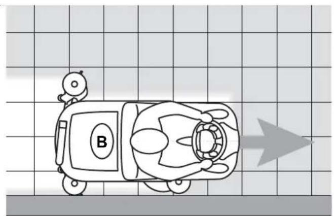
natural_image
Top-down line drawing of a cartoon car with a small robot and labeled 'B' on the front, set against a grid background with an arrow (no text or symbols beyond labels)Figura 3
P100364
Ajuste de la boquilla
Figura 5
P100366
Figura 6
P100367
LIMPIEZA DE LOS CEPILLOS/CEPILLOS CILÍNDRICOS

¡ADVERTENCIA!
Figura 8
P100368
Figura 8
P100369
Figura 9
P100370
CARGA DE LAS BATERÍAS

NOTA
Figura 10
P100371
P100359
VOLANTE COM PAINEL DE CONTROLO E COMANDOS
P100361A
UTILIZAÇÃO

ATENÇÃO!
Figura 1
P100362
Figura 2
P100363
natural_image
Top-down line drawing of a car with a labeled section 'A' and a gray arrow pointing downward on a grid background (no text or symbols beyond the label)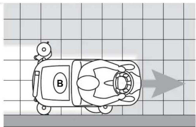
natural_image
Top-down line drawing of a cartoon car with a small robot and labeled 'B' on the front panel, set against a grid background with an arrow (no text or symbols beyond labels)Figura 3
P100364
Figura 5
P100366
Figura 6
P100367
LIMPEZA DAS ESCOVAS COM DISCO OU COM ROLO

ADVERTÊNCIA!
Figura 8
P100368
Figura 8
P100369
Figura 9
P100370
14600 21st Avenue North
Plymouth, MN 55447-3408
www.advance-us.com
Phone: 800-989-2235
Fax: 800-989-6566
©2010 Nilfisk-Advance, Inc.
- TABLE OF CONTENTS
- INTRODUCTION....2
- UNPACKING/DELIVERY 3
- SAFETY 3
- MACHINE DESCRIPTION....6
- USE 12
- MAINTENANCE 22
- SAFETY FUNCTIONS 29
- TROUBLESHOOTING....30
- SCRAPPING 30
- INTRODUCTION
- MANUAL PURPOSE AND CONTENTS
- TARGET
- HOW TO KEEP THIS MANUAL
- IDENTIFICATION DATA
- OTHER REFERENCE MANUALS
- SPARE PARTS AND MAINTENANCE
- CHANGES AND IMPROVEMENTS
- CONVENTIONS
- UNPACKING/DELIVERY
- SAFETY
- SYMBOLS
- DANGER!
- WARNING!
- CAUTION!
- NOTE
- CONSULTATION
- GENERAL INSTRUCTIONS
- MACHINE DESCRIPTION
- MACHINE STRUCTURE
- MACHINE STRUCTURE (Continues)
- STEERING WHEEL WITH CONTROL PANEL
- ACCESSORIES/OPTIONS
- WIRING DIAGRAM
- USE
- BATTERY CHECK/SETTING ON A NEW MACHINE
- Batteries (WET or GEL/AGM) already installed and ready to be used
- Without batteries
- BATTERY INSTALLATION AND BATTERY TYPE SETTING (WET OR GEL/AGM)
- Battery installation
- Battery type setting
- Battery charging
- BEFORE START-UP
- Brush/pad-holder installation/removal
- Cylindrical brush installation/removal
- Squeegee installation
- Solution/clean water tank fi lling
- Detergent tank fi lling
- Operator's position adjustment
- MACHINE START AND STOP
- Starting the machine
- Stopping the machine
- MACHINE OPERATION (SCRUBBING/DRYING)
- Squeegee adjustment
- Adjustment of the detergent concentration in the solution
- EcoFlex™ function
- EcoFlex™ system disabling procedure
- Working with brush/pad-holder extra pressure function activated (only for SC3000 26" Disc)
- Battery discharge during operation
- TANK EMPTYING
- Recovery tank emptying
- Solution/clean water tank emptying
- Cylindrical brush debris container emptying (only for cylindrical brush deck)
- AFTER USING THE MACHINE
- MACHINE LONG INACTIVITY
- FIRST PERIOD OF USE
- MAINTENANCE
- MACHINE WORKING HOUR CHECK
- SQUEEGEE CLEANING
- SQUEEGEE BLADE CHECK AND REPLACEMENT
- BRUSH/CYLINDRICAL BRUSH CLEANING
- RECOVERY TANK CLEANING
- SIDE SKIRT CHECK AND REPLACEMENT (only for 28" Cyl.)
- Check
- Overturning or replacement
- Assembly and height adjustment
- VACUUM SYSTEM MOTOR FILTER CLEANING
- SOLUTION FILTER CLEANING
- Preliminary procedures
- DETERGENT TANK CLEANING
- FUSE CHECK/REPLACEMENT
- SAFETY FUNCTIONS
- EMERGENCY PUSH-BUTTON
- ANTI-SKID SAFETY SYSTEM
- DRIVER'S SEAT MICROSWITCH
- ELECTROMAGNETIC BRAKE
- SCRAPPING
- TABLE DES MATIERES
- DESCRIPTION DE LA MACHINE 6
- UTILISATION 12
- ENTRETIEN 22
- CONSERVATION DU MANUEL
- STRUCTURE DE LA MACHINE
- STRUCTURE DE LA MACHINE (suite)
- VOLANT AVEC TABLEAU DE BORD
- ACCESSOIRES / OPTIONS
- NETTOYAGE DES BROSSES OU DES BROSSES CYLINDRIQUES
- AVERTISSEMENT !
- NETTOYAGE DU FILTRE DU MOTEUR DU SYSTEME D'ASPIRATION
- CHARGEMENT DES BATTERIES
- ESTRUCTURA DE LA MÁQUINA (Sigue)
- VOLANTE CON PANEL DE CONTROL Y MANDOS
- USO
- Ajuste de la boquilla
- LIMPIEZA DE LOS CEPILLOS/CEPILLOS CILÍNDRICOS
- CARGA DE LAS BATERÍAS
- VOLANTE COM PAINEL DE CONTROLO E COMANDOS
- UTILIZAÇÃO
- LIMPEZA DAS ESCOVAS COM DISCO OU COM ROLO
- ADVERTÊNCIA!
Brand : ADVANCE
Model : SC3000 EcoFlex
Category : Floor cleaner