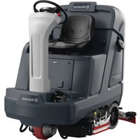
SC5000 34D - Floor cleaner ADVANCE - Free user manual and instructions
Find the device manual for free SC5000 34D ADVANCE in PDF.


| Product type | Rider scrubber |
| Brand | Advance (Nilfisk) |
| Model | SC5000 34D |
| Scrubbing width | 84.3 cm (33.2 in) |
| Dimensions (L x W x H) | 159 x 95 x 146 cm (62.6 x 37.5 x 57.7 in) |
| Shipping weight | 640 kg (1410 lb) |
| Gross vehicle weight | 848 kg (1870 lb) |
| Power supply | Battery 36 V, max capacity 420 Ah (C20) |
| Battery type | Wet lead-acid or AGM/VRLA (dry) |
| Solution tank capacity | 140 L (37 US gal) |
| Recovery tank capacity | 147 L (38.8 US gal) |
| Travel speed | 8 km/h (5 mph) forward, 4.8 km/h (3 mph) reverse |
| Max operating slope | 12% (6.8°) |
| Max transport slope | 20% (11°) |
| Brush type | Discs (2 x diameter 43.2 cm), 250 rpm |
| Detergent system | Integrated EcoFlex (depending on model), adjustable concentration |
| Control panel | Digital display, navigation keys, magnetic SmartKey |
| Main functions | Scrubbing, vacuuming, detergent (EcoFlex), emergency stop, flow and pressure regulation |
| Maintenance and cleaning | Tank draining, filter and squeegee cleaning, monthly lubrication, battery check |
| Safety | Emergency stop, electromagnetic brake, impact detector, magnetic key, seat switch |
| Spare parts and repairability | Parts available via Nilfisk, repairs by qualified personnel, separate service manual |
| Usage | Commercial, indoor only (hotels, schools, factories, stores, offices) |
Frequently Asked Questions - SC5000 34D ADVANCE
User questions about SC5000 34D ADVANCE
0 question about this device. Answer the ones you know or ask your own.
Ask a new question about this device
Download the instructions for your Floor cleaner in PDF format for free! Find your manual SC5000 34D - ADVANCE and take your electronic device back in hand. On this page are published all the documents necessary for the use of your device. SC5000 34D by ADVANCE.
USER MANUAL SC5000 34D ADVANCE
Instructions for Use
Instructions for Use
Original Instructions
natural_image
Technical line drawing of a cleaning or inspection machine (no text or symbols visible)Model No:
56117001 (34D), 56117003 (32C), 56117004 (36C)

WARNING:
The operation of this machine is strictly reserved to trained and qualified operators.

Advance
by Nilfisk
TABLE OF CONTENTS
Introduction....3
Parts and Service....3
Modifications 3
Name Plate....3
Uncrate the Machine 4
Transporting the Machine....4
Cautions and Warnings.... 5
Regulatory....7
Know Your Machine....8
Control Panel....10
Information Menu Display....12
Magnetic SmartKey 14
Prepare the Machine for Use....14
Batteries 14
Install the Batteries....14
Install the Brushes (disc system)....16
Install the Brushes (cylindrical system) 17
Filling the Solution Tank ....18
Solution Tank Indicator....18
Squeegee Installation....19
Detergent System Preparation (Ecoflex Models Only) 20
Fill the Detergent Cartridge 20
Detergent System Purge (EcoFlex Models Only) .....21
Detergent System Use (Ecoflex) 22
Operating the Machine....24
Starting the Machine 24
Stopping the Machine....24
Wet Vacuuming 26
After Use 27
Maintenance....27
Maintenance Schedule....27
Cleaning Recovery Tank 28
Cleaning Solution Filter 28
Lubricating the Machine 29
Electromagnetic Brake 29
Charging Wet Batteries 30
Charging GEL/AGM (VRLA) Batteries 31
Squeegee Maintenance 32
Squeegee Adjustment 32
Side Blade Maintenance 34
Side Blade Height Adjustment....34
Side Blade Pressure Adjustment - Cylindrical Only 36
Side Blade - Double Scrub Position 36
Troubleshooting 37
General Machine Troubleshooting 37
Fault Code Display 38
Fault Code History....39
Specifications 40
Accessories / Options 40
Material Composition and Recyclability....40
Solution Flow Rates 40
Technical Specifications ....41
INTRODUCTION
This manual will help you get the most from your Advance Scrubber. Read it thoroughly before operating the machine.
Note: Bold numbers in parentheses indicate an item illustrated on pages 8 – 11.
This machine is intended for commercial use, for example in hotels, schools, factories, shops, offices and rental businesses. The Advance SC5000 is a battery powered floor cleaning machine.
WARNING:
The operation of this machine is strictly reserved to trained and qualified operators.
CAUTION!
- Use extreme CAUTION when operating this machine. Be certain that you are thoroughly familiar with all operating instructions before using this machine. If you have any questions, contact your supervisor or your local Advance Dealer.
- If the machine malfunctions, do not try to correct the problem unless your supervisor directs you to do so. Have a qualified company mechanic or an authorized Advance Dealer service person make any necessary corrections to the equipment.
- Use extreme care when working on this machine. Loose clothing, long hair, and jewelry can get caught in moving parts. Turn the Power Switch OFF and remove the magnetic key before servicing the machine. Use good common sense, practice good safety habits and pay attention to the yellow decals on this machine.
- Drive the machine slowly on inclines.
- The maximum rated incline for scrubbing is 12% (6.8°). The maximum rated incline during transport is 20% (11°).
PARTS AND SERVICE
Repairs, when required, should be performed by Nilfisk, Inc., who employs factory trained service personnel, and maintains an inventory of Advance original replacement parts and accessories.
Call Nilfisk, Inc. for repair parts or service. Please specify the Model and Serial Number when discussing your machine.
MODIFICATIONS
Modifications and additions to the cleaning machine which affect capacity and safe operation shall not be performed by the customer or user without prior written approval from Nilfisk, Inc. Unapproved modifications will void the machine warranty and make the customer liable for any resulting accidents.
NAME PLATE
The Model Number (also known as Part Number) and Serial Number of your machine are shown on the Nameplate, located on the rear of the steering column.
Date of Manufacture "Date Code" is marked on the nameplate. Date Code: A21, means January 2021.
This information is needed when ordering repair parts for the machine. Use the space below to note the Model Number and Serial Number of your machine for future reference.
MODEL NO.
SERIAL NO.
UNCRATE THE MACHINE
When the machine is delivered, carefully inspect the shipping packaging and the machine for damage. If damage is evident, save the shipping carton (if applicable) so that it can be inspected. Contact the Nilfisk Customer Service Department immediately to file a freight damage claim. Refer to the unpacking instruction sheet included with the machine to remove the machine from the pallet.
TRANSPORTING THE MACHINE
CAUTION!
Before transporting the machine in an open truck or trailer, make sure that . . .
- All tanks are empty.
- All access doors are latched securely.
- Lower scrub deck and squeegee then press Emergency Stop (A) or disconnect batteries to prevent them from raising when the machine is powered off.
- The machine is tied down securely - see Tie Down Locations (21) in "Know Your Machine". Only use locations designated as "Tie Down Locations" to secure the machine during transport. Using any other location of the machine to tie down the machine may cause damage or injury.
- The machine's electromagnetic brake is engaged (not manually overridden), see "Electromagnetic Brake" section if necessary.
- The machine is turned off and the magnetic SmartKey is removed.
CAUTIONS AND WARNINGS
SYMBOLS
Nilfisk uses the symbols below to signal potentially dangerous conditions. Always read this information carefully and take the necessary steps to protect personnel and property.

DANGER!
Is used to warn of immediate hazards that will cause severe personal injury or death.

WARNING!
Is used to call attention to a situation that could cause severe personal injury.

CAUTION!
Is used to call attention to a situation that could cause minor personal injury or damage to the machine or other property.


Read all instructions before using.
GENERAL SAFETY INSTRUCTIONS
Specific Cautions and Warnings are included to warn you of potential danger of machine damage or bodily harm. This machine is intended for commercial use, for example in hotels, schools, factories, shops, offices and rental businesses.

WARNING!
- This machine shall be used only by properly trained and authorized persons.
- This machine is not intended for use by persons (including children) with reduced physical, sensory or mental capabilities, or lack of experience and knowledge, unless they have been given supervision or instruction concerning use of the machine by a person responsible for their safety.
- Children should be supervised to ensure that they do not play with the appliance.
- Close attention is necessary when used near children.
• While on ramps or inclines, avoid sudden stops. Avoid abrupt sharp turns. Use low speed down ramps. - Keep sparks, flame and smoking materials away from batteries. Explosive gases are vented during normal operation.
- Charging the batteries produces highly explosive hydrogen gas. Charge batteries only in well-ventilated areas, away from open flame. Do not smoke while charging the batteries.
- Remove all jewelry when working near electrical components.
- Turn the power switch off, remove the magnetic key and disconnect the batteries before servicing electrical components.
- Never work under a machine without safety blocks or stands to support the machine.
- Do not dispense flammable cleaning agents, operate the machine on or near these agents, or operate in areas where flammable liquids exist.
- Do not pressure wash operator control panel, circuit breaker panel or batteries.
- Only use the brushes provided with the appliance or those specified in the instruction manual. The use of other brushes may impair safety.
- Observe the Gross Vehicle Weight, GVW, of the machine when loading, driving, lifting or supporting the machine.
- Do not use the machine without a falling object protective structure (FOPS) in areas where it is likely that the operator is hit by falling objects.
- Do not leave the machine unattended without being sure that it cannot move independently.
CAUTIONS AND WARNINGS - CONTINUED
CAUTION!
- This machine is not approved for use on public paths or roads.
- This machine is not suitable for picking up hazardous dust.
- When operating this machine, ensure that third parties, particularly children, are not endangered.
• Before performing any service function, carefully read all instructions pertaining to that service task. - Do not leave the machine unattended without first turning the power switch off and removing the magnetic key.
- Turn the power switch off and remove the magnetic key, before changing the brushes, and before opening any access panels.
• Take precautions to prevent hair, jewelry, or loose clothing from becoming caught in moving parts. - Use caution when moving this machine in below freezing temperature conditions. Any water in the solution, recovery or detergent tanks or in the hose lines could freeze, causing damage to valves and fittings. Flush with windshield washer fluid.
- The batteries must be removed from the machine before the machine is scrapped. The disposal of the batteries should be safely done in accordance with your local environmental regulations.
- CAUTION - This machine is for indoor use only.
- CAUTION - This machine shall be stored indoors only.
- Do not use on surfaces having a gradient exceeding that marked on the machine.
• All doors and covers are to be positioned as indicated in the instruction manual before using the machine. - Only use locations designated as “Tie Down Locations” to secure the machine during transport. Using any other location of the machine to tie down the machine may cause damage or injury.
- Do not operate the machine on a grade outside that which is written on the nameplate.
- Do not carry passengers on any part of the machine.
- In order to prevent unauthorized use of the machine, the power source shall be switched off or locked, and key removed.
• Machines left unattended shall be secured against unintentional movement.
SAVE THESE INSTRUCTIONS
REGULATORY
SC5000 with MultitConn1
FCC:
FCC-ID: 2AVNE-TC1
This device and its antenna must not be co-located or operating in conjunction with any other antenna or transmitter. Non body-worn devices must be placed at least 8" (20cm) away from the body.
IC:
IC-ID: 25476-TC1
This device complies with Industry Canada license-exempt RSS standards RSS-210 and/or RSS-247. The term “IC” before the equipment certification number only signifies the Industry Canada technical specifications were met. It does not imply that Industry Canada approved the equipment. The radio transmitter has been approved by Industry Canada to operate only with the antenna supplied. Use of any other antenna is strictly prohibited for use with this product. This device complies with the ICES RF radiation exposure limits set forth for an uncontrolled environment. This equipment should be installed and operated with a minimum distance of 20cm between the radiator and any part of the human body.
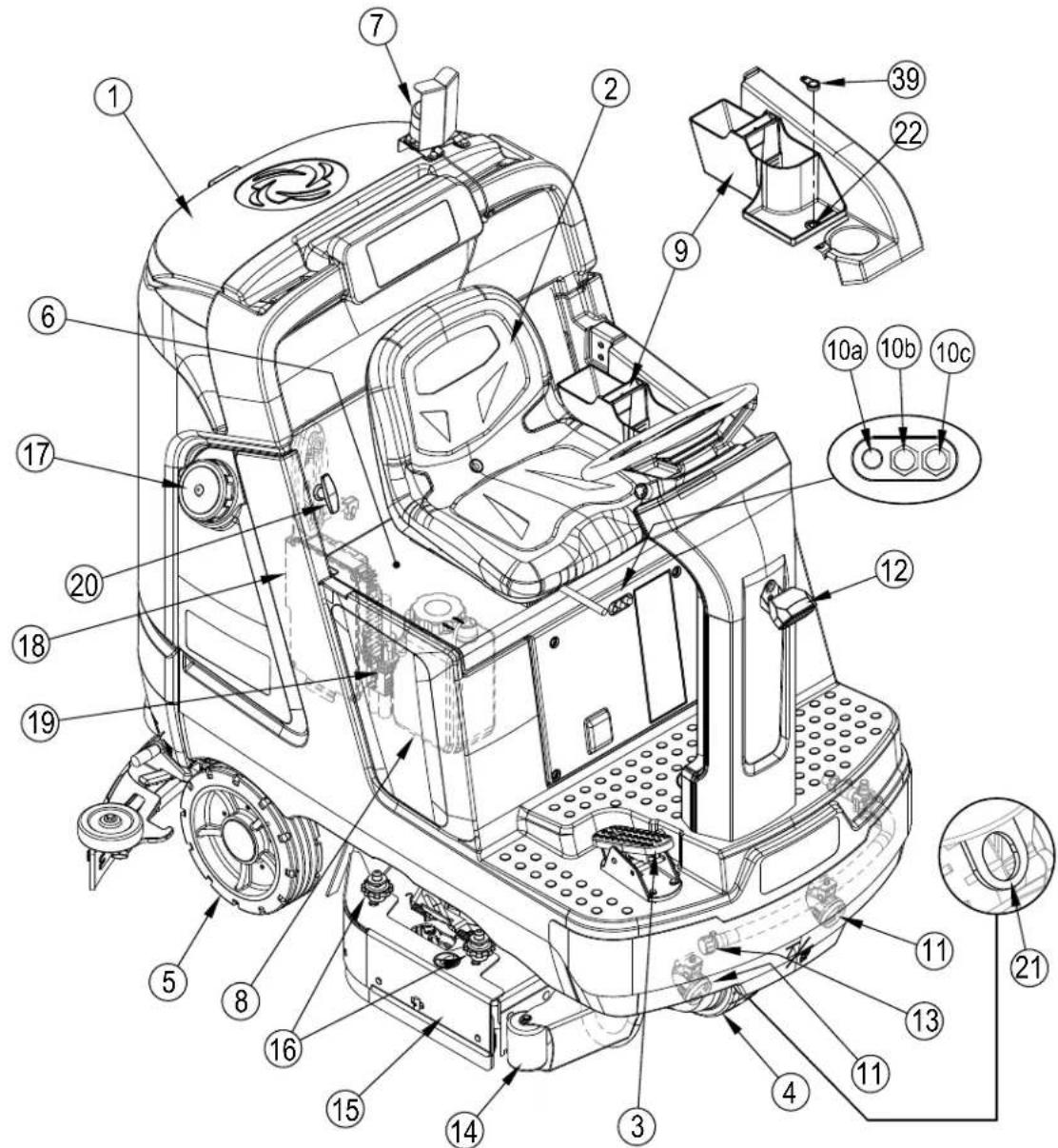
KNOW YOUR MACHINE
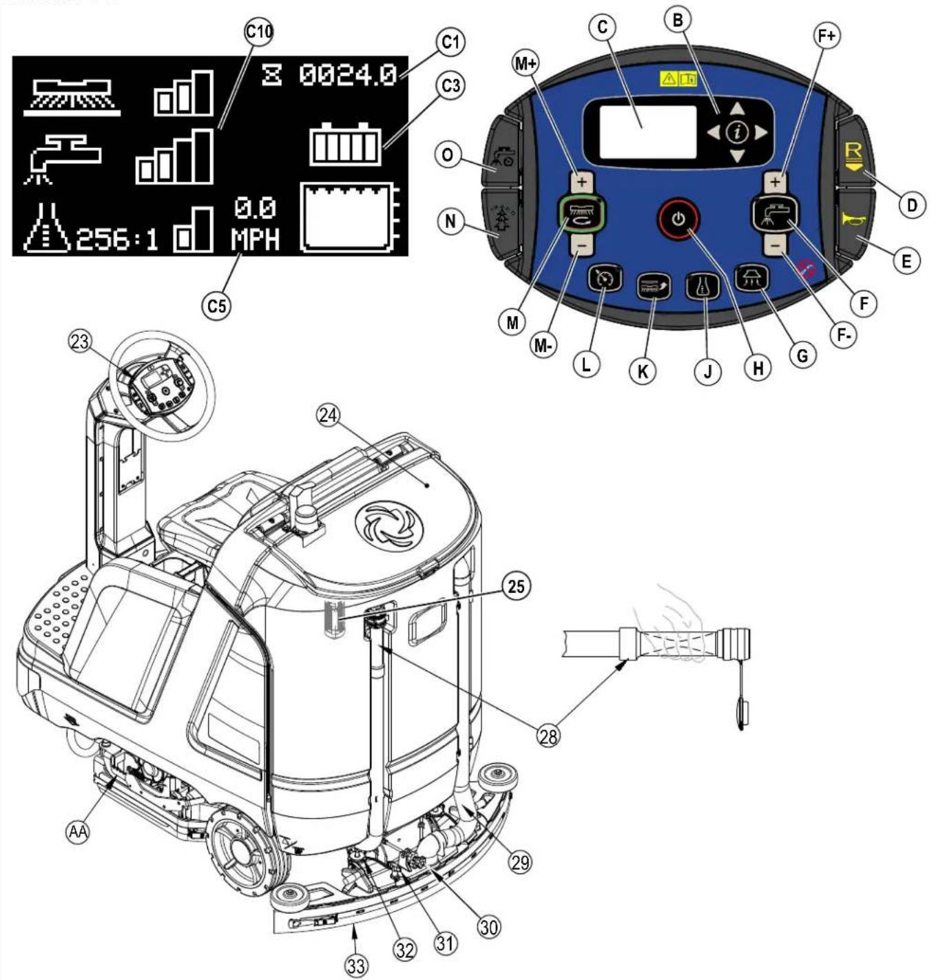
As you read this manual, you will occasionally run across a bold number or letter in parentheses - example: (2). These numbers refer to an item shown on these pages unless otherwise noted. Refer back to these pages whenever necessary to pinpoint the location of an item mentioned in the text.
1 Recovery Tank Cover
2 Operator's Seat
3 Drive Pedal
4 Drive Wheel
5 Rear Wheel
6 Battery Compartment (under seat)
7 Warning Beacon
8 Detergent Cartridge (EcoFlex models only)
9 Storage Box
10 Circuit Breakers
10a Drive Controller 70 Amp (CB2)
10b Control Board 5 Amp (CB1)
10c Control Board 5 Amp (CB3)
11 Headlights (optional)
12 Blue Light (optional)
13 Solution Tank Drain Hose
14 Front Roller Bumper
15 Scrub Deck
16 Side Blade Assembly Removal Knobs
17 Solution Tank Fill
18 Onboard Battery Charger (optional)
19 Machine Battery Connector
20 Battery Compartment Latch
21 Tie-Down Location (1 front)
22 SmartKey™ Reader
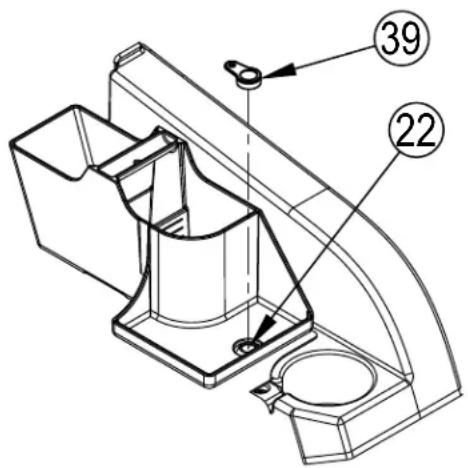
39 Magnetic SmartKey™
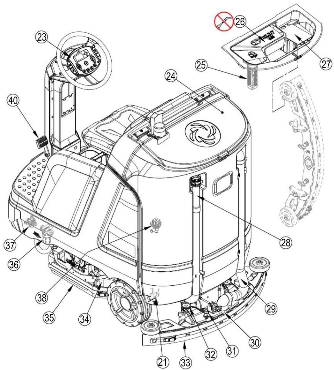
KNOW YOUR MACHINE
21 Tie Down Location (2 rear)
23 Control Panel
24 Recovery Tank Cover
25 Recovery Tank Shutoff Float
26 Vacuum Motor Filter Housing
27 Debris Catch Tray
28 Recovery Tank Drain Hose
29 Recovery Hose
30 Squeegee Tilt Adjust Knob
31 Squeegee Mount Thumb Nuts
32 Squeegee Caster Lock Knob
33 Squeegee Assembly
34 Hopper (Cylindrical only)
35 Scrub Deck
36 Solution Filter
37 Solution Shutoff Valve
38 Solution Solenoid Valve (on scrub deck)
40 Brake Pedal
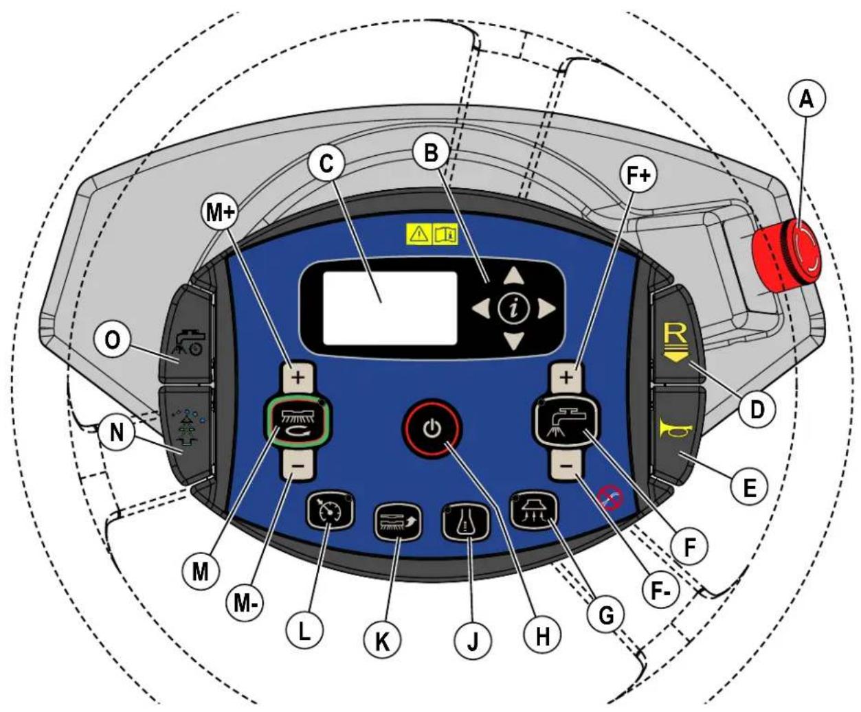
CONTROL PANEL
A Emergency Stop
B Information Switch & Navigation Switches
C Display (see Control Panel-Continued)
D Reverse Paddle
E Horn Paddle
F Solution Switch
F+ Solution Flow Increase Switch
F- Solution Flow Decrease Switch
G Vacuum Switch
H Power Switch
J Detergent Switch
K Brush Install Switch
L Speed Limiter Switch
M One-Touch™ Scrub ON/OFF Switch
M+ Scrub Pressure Increase Switch
M- Scrub Pressure Decrease Switch
N Burst of Power Paddle
O Timed Solution Off Paddle
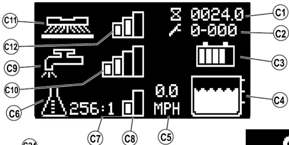
CONTROL PANEL - CONTINUED
C1 Hour Meter (Drive Hours)
C2 Active Fault Codes
C3 Battery Indicator
C4 Solution Tank Level Indicator
C5 Speed (MPH or KPH)
C6 Detergent Indicator (EcoFlex models only)
C7 Detergent Percentage Indicator
C8 Detergent Indicator Bar Graph
FIRST = Minimum Concentration Detergent Mode
SECOND = Maximum Concentration Detergent Mode
NONE = Off
C9 Solution Flow Indicator
C10 Solution Flow Rate Bar Graph
FIRST = Low
SECOND = Medium
THIRD = High
FOURTH = Extreme
NONE = Off
C11 Scrub Pressure Indicator
C12 Scrub Brush Pressure Bar Graph
FIRST = Regular
SECOND = Heavy
THIRD = Extreme
NONE = Off
C14 Battery Low Voltage Indicator
C15 Burst of Power Indicator (EcoFlex models only)
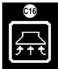
C16 Vacuum Indicator
C17 Wand Indicator
C18 Brush Install Indicator
C19 Purge Indicator (EcoFlex models only)
C20 Emergency Stop Activated Indicator
C21 No Key Indicator
C22 Key Read Error Indicator (see Troubleshooting)
C23 Restricted User Key Indicator (see Troubleshooting)
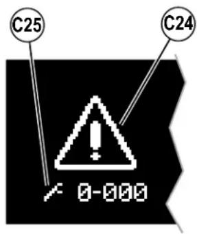
C24 Critical Fault Indicator
C25 Fault Code (Critical)
C26 Impact Lockout Indicator (see page 13)
C27 Reverse Indicator

natural_image
Simple white checkmark inside a square frame with a circular badge showing number 20 (no text or symbols beyond the number)

natural_image
Simple graphic of three upward-pointing triangles with a small circle in the corner (no text or symbols)
natural_image
Pixelated white padlock icon on black background, no text or symbols present
natural_image
Pure electrical circuit symbol for a battery, no text or labels present
natural_image
Simple icon of a laboratory flask with a circular head, no text or symbols present
natural_image
Simple icon of a sun with a tree on a path, no text or symbols present
natural_image
Two abstract white icons on black background: one resembling a key with a circle, the other a mechanical component (no text or symbols)
natural_image
Pure electrical circuit lines without any symbolsINFORMATION MENU DISPLAY
Menu Display
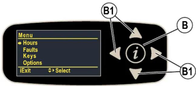
Pressing the Information Switch (B) will bring up the menu shown below which allows the operator to change machine settings and gather machine information. Use the four Navigation Arrows (B1) (up, down, left & right) to move through the menu and the information switch to exit the menu.
flowchart
graph TD
    A["Menu"] --> B["Hours"]
    B --> C["Faults"]
    C --> D["Keys"]
    D --> E["Options"]
    E --> F["iExit"]
    F --> G["Select"]
    H["B1"] --> I["i"]
    J["B"] --> I
    K["B1"] --> I
Menu visible with either blue (User) or yellow (Supervisor) SmartKey.
| Menu Level | Notes | |
| 1 | 2 | |
| Hours | Displays various system hours | |
| On Time | Displays Power ON hours | |
| Drive Time | Displays drive(non-neutral) hours | |
| Scrub Time | Displays scrub/brush ON hours | |
| Recovery Time | Displays recovery/vacuum ON hours | |
| Faults** | ||
| Active Faults | Displays list of active faults w/timestamp and description | |
| Fault History | Displays list of fault history w/timestamp and description | |
| Keys | ||
| Read Key | Read the key serial number, family and type for key inserted into holder- if user key, allows supervisor to add to key list | |
| Key List | Display the current approved user key listsupervisor can also remove selected key from list | |
**See Fault Code Display
Menu visible only with yellow (Supervisor) SmartKey.
| Menu Level | Notes | ||
| 1 2 3 | |||
| Options | User selectable options | ||
| Language | English*ItalianoDeutschPortugueseFrançaisEspañol | Menu display language | |
| Floor | Standard*SmoothPolisher** | Floor type**polisher only available for 34D machines | |
| Scrub Startup | LightHeavyExtremeLast Used* | Scrub level at start | |
| Scrub Max | LightHeavyExtreme* | Maximum scrub level allowed | |
*Default setting
INFORMATION MENU DISPLAY - CONTINUED
Options Menu visible only with yellow (Supervisor) SmartKey.
System Menu visible with either blue (User) or yellow (Supervisor) SmartKey
| Menu Level | Notes | ||
| 1 2 3 | |||
| Options | User selectable options | ||
| Solution | Proportional*FixedUK | Solution mode; Proportional – solution flow increases with speed of machine. Fixed – Solution flow stays the same despite machine speed. UK (United Kingdom) – solution flow is reduced to conserve water. | |
| Solution In Rev | No*Yes | Leave solution on in reverse? | |
| Lock Detergent | No*Yes | Lockout detergent percentage adjustment for user? | |
| Beacon | On*Off | Beacon light on/off | |
| Burst Of Power (s) | min = 60*max = 300step = 60 | Burst-of-power (BOP) time span (seconds) EcoFlex | |
| Fwd Speed Max (%) | min = 50max = 100*step = 10 | Maximum forward speed as percentage of maximum available speed | |
| Lock Speed Limit | No*Yes | Lockout scrub speed limit for user? | |
| Inactivity Time (min) | min = 1max = 30step = 1default = 15 | Inactivity time before putting machine in sleep mode (minutes) | |
| Impact Detect | Off*LogLockout | Impact detection statusLog – Impact is recordedLockout – Impact is recorded and User is locked out of scrub functions (Display shows (C26)) until machine is reset with a Supervisor key. | |
| Impact Level | High*Low | Impact detection sensitivity level. If nuisance tripping occurs (i.e. driving over a floor transition), adjust setting to low. | |
| System | |||
| MMC Firmware | Main controller (mmc) firmware revision | ||
| UI Firmware | User interface panel (ui) firmware revision | ||
| CSP190-Comm F/W | Drive controller comm firmware revision | ||
| CSP190-Motor F/W | Drive controller main/motor control firmware revision | ||
| MMC S/N | Main controller (mmc) pcb serial number | ||
| UI S/N | User interface panel (ui) pcb serial number | ||
| Impact Log | Display list of impact events with max value, timestamp and user id (only if enabled)- single item view will show max values for each axis (x,y,z) | ||
*Default setting
SERVICE NOTE: Additional menus (Service and Configuration) are accessible only through service/technician mode. The service menu allows observing operational and user parameters. The configuration menu allows adjusting machine settings. See Service Manual for more details.
MAGNETIC SMARTKEY
The use of a Magnetic SmartKey (39) is required to operate this machine. Pressing the power switch without a key in place on the SmartKey Reader (22) will cause the machine to momentarily turn on and display No Key Indicator (C21) before turning off.
There are two different Magnetic SmartKeys (39).
- The "User" (blue) key allows a basic level of access to the information menu (press Information Switch (B)).
- The "Supervisor" (yellow) key allows an additional level of access to see Options Menu.
FIGURE 1-1
PREPARE THE MACHINE FOR USE
BATTERIES
If your machine shipped with batteries installed do the following:
- Check that the batteries are connected to the machine.
- Turn ON the Power Switch (H) and check the Battery Indicator (C3). If the gauge is completely filled the batteries are ready for use. If the gauge is less than full the batteries should be charged before use. See "Charging The Batteries" section.
- IMPORTANT!: IF YOUR MACHINE HAS AN ONBOARD BATTERY CHARGER REFER TO THE OEM PRODUCT MANUAL FOR INSTRUCTIONS REGARDING SETTING THE CHARGER FOR BATTERY TYPE.
If your machine shipped without batteries installed do the following:
- Consult your Authorized Advance dealer for recommended batteries.
• Install the batteries by following the instructions below. - IMPORTANT!: IF YOUR MACHINE HAS AN ONBOARD BATTERY CHARGER REFER TO THE OEM PRODUCT MANUAL FOR INSTRUCTIONS REGARDING SETTING THE CHARGER FOR BATTERY TYPE.
INSTALL THE BATTERIES
WARNING!
Use extreme caution when working with batteries. Sulfuric acid in batteries can cause severe injury if allowed to contact the skin or eyes. Explosive hydrogen gas is vented from the batteries through openings in the battery caps. This gas can be ignited by any electrical arc, spark or flame. Do not install any lead-acid battery in a sealed container or enclosure. Hydrogen gas from overcharging must be allowed to escape.
When Servicing Batteries...
- Remove all jewelry
- Do not smoke
- Wear safety glasses, rubber gloves and a rubber apron
• Work in a well-ventilated area - Do not allow tools to touch more than one battery terminal at a time
• ALWAYS disconnect the negative (ground) cable first when replacing batteries to prevent sparks. - ALWAYS connect the negative cable last when installing batteries.
BATTERIES - CONTINUED
CAUTION!
Electrical components in this machine can be severely damaged if the batteries are not installed and connected properly. Batteries should be installed by Nilfisk or by a qualified electrician.
1 Remove the batteries from their shipping crate and carefully inspect them for cracks or other damage. If damage is evident, contact the carrier that delivered them or the battery manufacturer to file a damage claim.
2 Turn the Power Switch (H) OFF and remove the Magnetic SmartKey (39).
3 Rotate the Battery Compartment Latch (20) to unlock then tip the seat forward (the gas spring holds the seat open).
4 If installed remove the overhead guard.
5 For additional access the recovery tank can be removed from the machine. NOTE: Disconnect the recovery hose, vacuum motor wiring and warning beacon wiring then lift the tank straight up and off the machine, using two people or an overhead hoist.
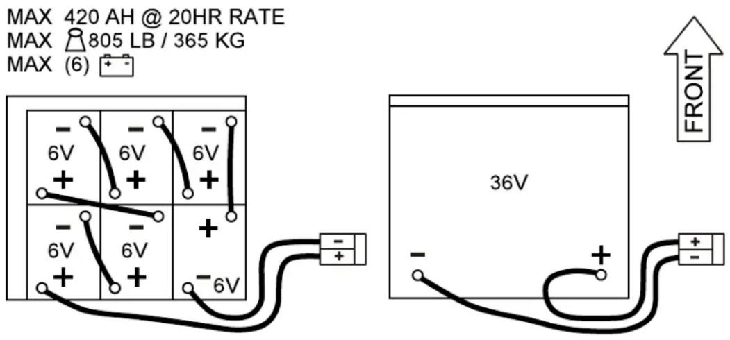
6 Your machine comes from the factory with enough battery cables to install six 6 volt batteries. Using at least (2) people and an appropriate lifting strap, carefully lift the batteries into the battery compartment and arrange them exactly as shown in FIGURE 2-1. Secure the batteries as close to the rear and right side of the machine as possible. Use battery spacer to keep batteries from moving. If installing a mono-block battery use an overhead hoist.
7 Install the battery cables as shown. Position the cables so the battery caps can be easily removed for battery service.
IMPORTANT!: The protective caps supplied with the batteries need to be left on or re-used to completely cover the portion of the battery terminals that are not being protected by the battery cable terminal cover boots supplied with the battery cables. This also applies to the in-line fuse holder boot.
8 Carefully tighten the nut in each battery terminal until the terminal will not turn. Do not over-tighten the terminals, or they will be very difficult to remove for future service.
9 Coat the terminals with spray-on battery terminal coating (available at most auto parts stores).
10 Put one of the black rubber boots over each of the terminals and connect the Machine Battery Connector (19).
11 Make sure the fuse holder boot is covering the fuse holder, the cable end of the Machine Battery Connector (19), and as much of the battery terminal as possible. Leave the protective caps supplied with the batteries in place or re-use to cover the terminal areas not protected by the terminal cover boots.
When changing batteries or the charger, please contact your local authorized service center for correct battery, charger and machine settings to prevent battery damage.
FIGURE 2-1
INSTALL THE BRUSHES (DISC SYSTEM)

CAUTION!
Turn the machine OFF at the power switch, before changing the brushes, and before opening any access panels.
1 Make sure the Scrub Deck is in the RAISED position. Make sure the Power Switch (H) is off.
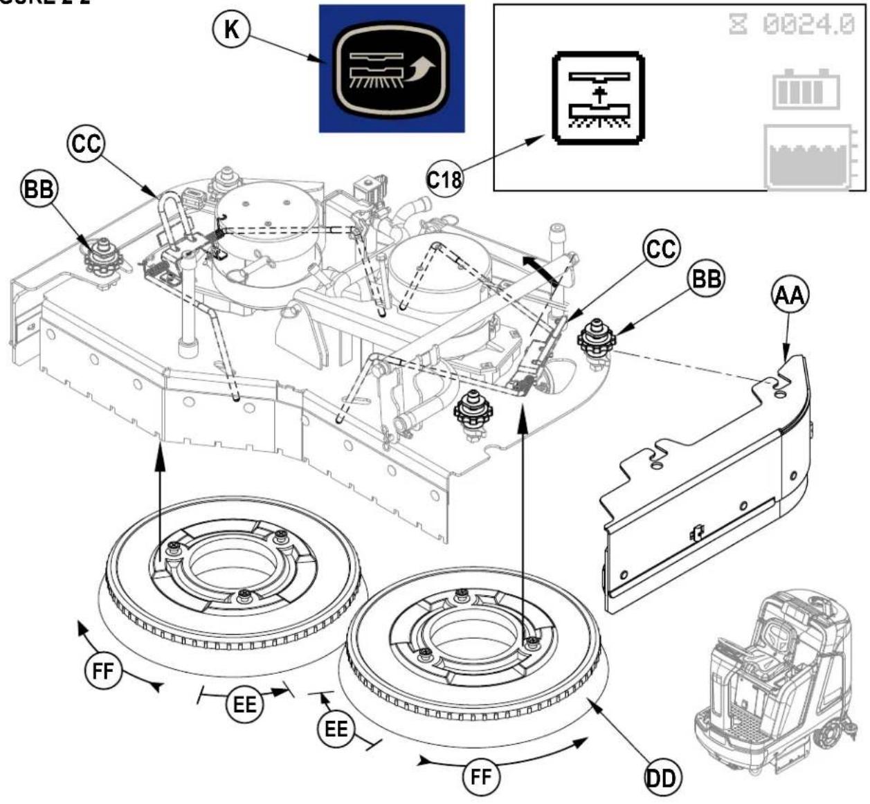
2 See Figure 2-2. Remove both Side Blade Assemblies (AA). NOTE: The blade assemblies are held in place by two large Knobs (BB). Loosen these knobs and slide the Blade Assemblies (AA) forward slightly and then off of the Scrub Deck.
3a To manually install the brushes:
Lift the Brushes (DD) (or pad holders) and align the lugs on the brush with the holes on the mounting plate then turn to lock in place (turn the outside edge of brush towards the front of machine as shown by arrow (EE)).
3b To use the automatic Brush Install feature:
i. Press the Guide Bar (CC) forward while sliding the brush under the deck and stop when the brush is contacting both legs of the guide bar. Repeat this step for the brush on the other side of the deck. NOTE: Do not push the first brush out of position with the second brush. ii. Turn the machine ON at the Power Switch (H). (SCRUB SYSTEM MUST BE OFF and MACHINE MOTIONLESS)

CAUTION!
Keep hands and feed out from underneath the deck. Take precautions to prevent hair, jewelry, or loose clothing from becoming caught in moving parts.
iii. Press the Brush Install Switch (K) the display will show Brush Install Indicator (C18) then wait for the brush install sequence to finish.
4 Reinstall the side blade assemblies. NOTE: While scrubbing the brushes rotate as shown by arrows (FF).
FIGURE 2-2
INSTALL THE BRUSHES (CYLINDRICAL SYSTEM)
CAUTION!
Turn the machine OFF at the power switch, before changing the brushes, and before opening any access panels.
1 Make sure the Scrub Deck is in the RAISED position. Make sure the Power Switch (H) is off.
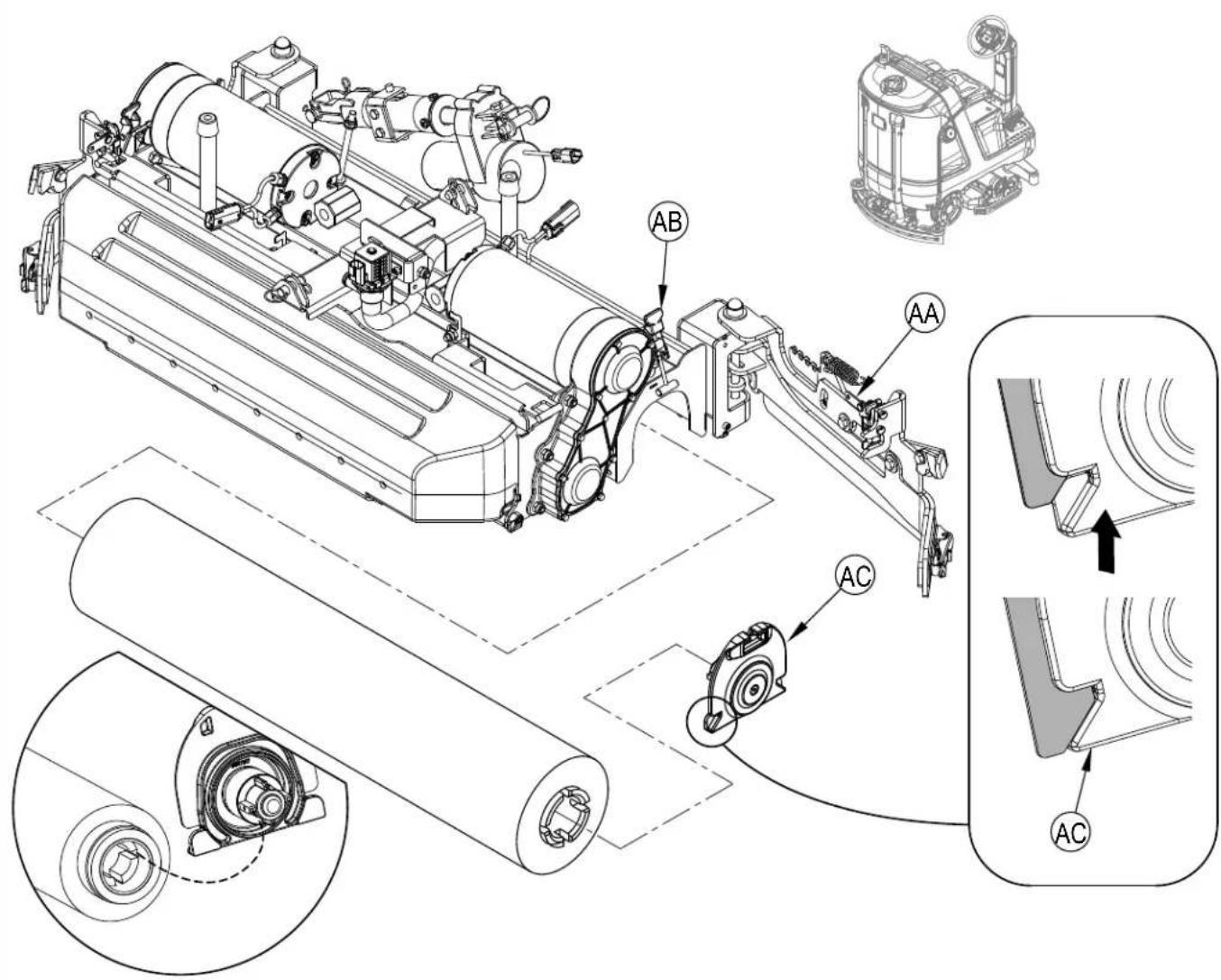
2 See Figure 2-3. Unlatch and swing open both Side Blade Assemblies (AA).
3 Unhook the Latch (AB) on top of the Idler Assemblies (AC) and remove.
4 Slide the brush into the housing, lift slightly, push and turn until the tabs on the drive hub seat into the notches in the brush. NOTE: The idler is designed with a snug fit into the brush to reduce vibration. Re-install the Idler Assemblies (AC) make sure the tabs on the idler are inside of the weldment (as shown in inset of Figure 2-3). Secure with Latch (AB). Close and latch both the Blade Assemblies (AA).
FIGURE 2-3
FILLING THE SOLUTION TANK
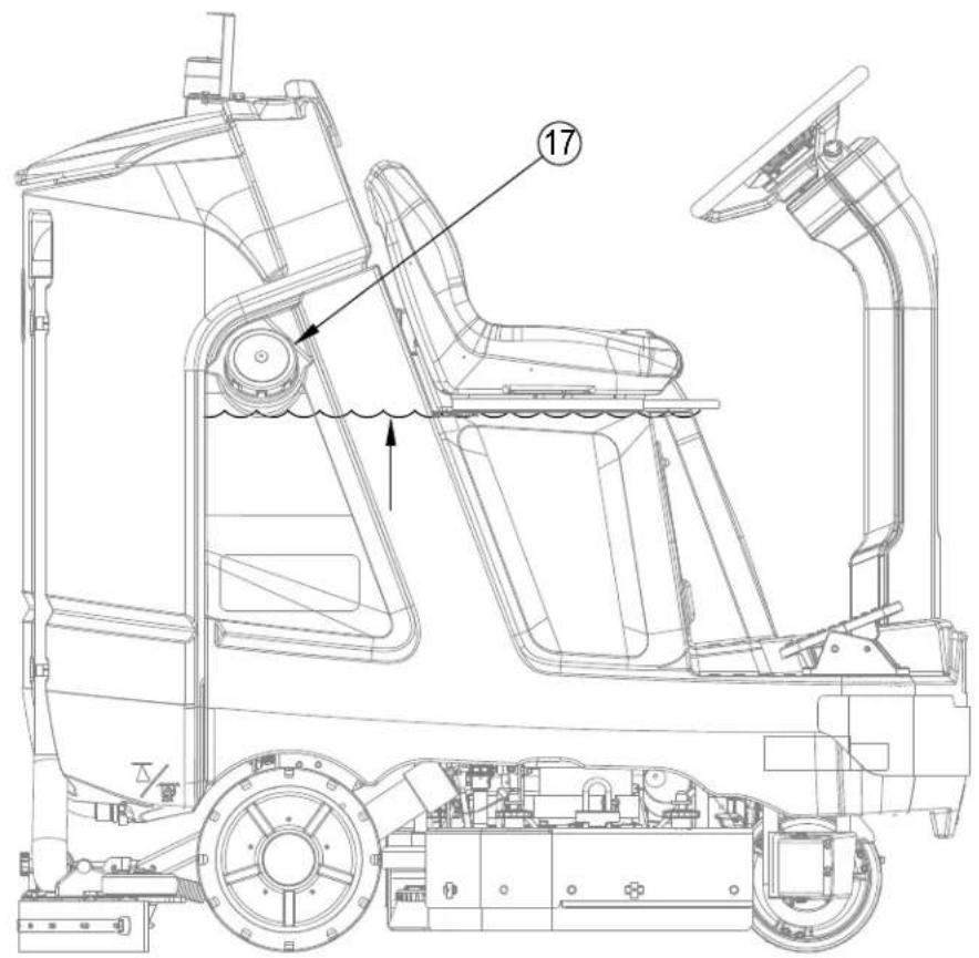
See Figure 2-4. Fill the solution tank with a maximum of 37 gallons (140 Liters) of cleaning solution. The solution tank can be filled to the bottom of the Solution Fill (17). The solution should be a mixture of water and the proper cleaning detergent for the job. Always follow the dilution instructions on the detergent container label. NOTE: EcoFlex machines can either be used conventionally with detergent mixed in the tank or the detergent dispensing system can be used. When using the detergent dispensing do not mix detergent in the tank, plain water should be used.

CAUTION!
Use only low-foaming, non-flammable liquid detergents intended for machine application. Water temperature should not exceed 130 degrees Fahrenheit (54.4 degrees Celsius)
FIGURE 2-4
SOLUTION TANK INDICATOR
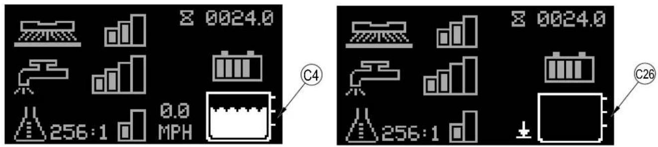
See Figure 2-5. The solution tank has three level sensors that correspond with three measurement points. The Solution Level Indicator (C4) displays the level (1-3) of the solution in the tank. Once the tank is empty the Solution Empty Indicator (C26) will flash on the display.
FIGURE 2-5
SQUEEGEE INSTALLATION
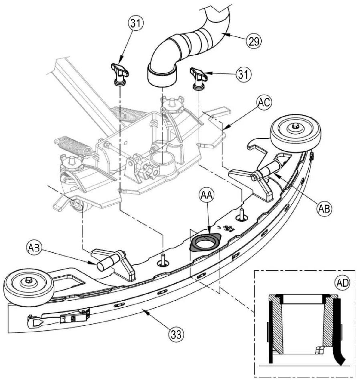
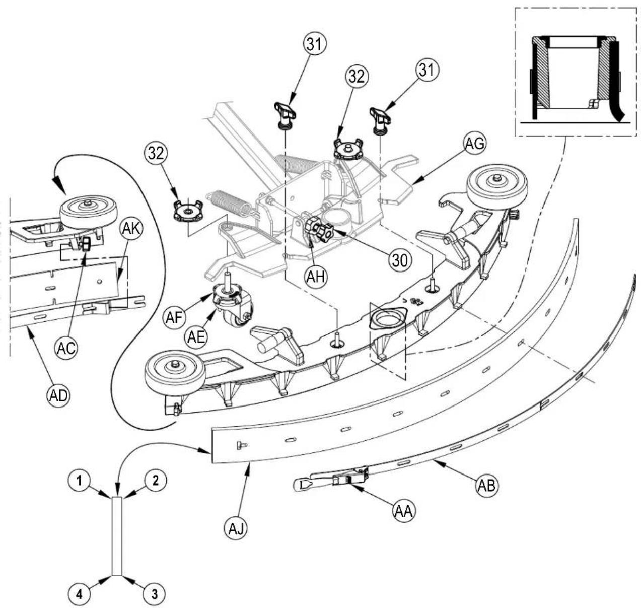
1 See Figure 2-6. Ensure the Squeegee Seal (AA) is free from debris and installed on the Squeegee Assembly (33). Lift the squeegee assembly by its Handles (AB) and slide it onto the Squeegee Mount (AC) and tighten the Squeegee Mount Thumb Nuts (31).
2 Connect the Recovery Hose (29) to the squeegee mount (AC).
3 Lower the squeegee and move the machine ahead slightly. Check that the rear squeegee blade touches the floor evenly across its entire width and is bent over slightly as shown in the squeegee cross section (AD). If necessary adjust the rear squeegee to the proper height and tilt by following the steps in the "Squeegee Adjustment" section.
FIGURE 2-6
DETERGENT SYSTEM PREPARATION (ECOFLEX MODELS ONLY)
FILL THE DETERGENT CARTRIDGE
CAUTION!
Always follow the instructions on the labels of the detergent cartridge when using floor cleaning detergents. Wear the appropriate personal protective equipment such as gloves and eye protection when handling floor cleaning detergents.
In the event of a detergent spill follow these four steps:
- Communicate the hazard. Immediately notify others working in the area and any supervisory personnel of the hazard, and if the situation warrants it, evacuate the area.
- Control the spill. Ensure the spill does not become any worse.
- Contain the hazard.
- Clean up the spill and any damage safely.
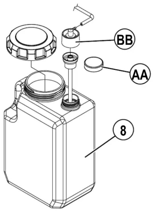
The Detergent Cartridge (8) is located beneath the seat. Fill the detergent cartridge with a maximum of 1 gallon (4 Liters) of detergent.
SERVICE NOTE: Remove the detergent cartridge from the machine prior to filling to avoid spilling detergent on the machine.
It is recommended that a separate cartridge be used for each detergent you plan to use. The detergent cartridges have a white decal on them so you can write the detergent name on each cartridge for clarification. When installing a new cartridge, remove the Factory Cap (AA) and place the cartridge in the machine. Install the Dry Break Cap (BB) and detergent hose as shown in Figure 2-7.
The system should be purged of previous detergent when switching to a different detergent (see "To Purge When Changing Detergent").
FIGURE 2-7
DETERGENT SYSTEM PURGE (ECOFLEX MODELS ONLY)
To Purge When Changing Detergent (SCRUB AND SOLUTION SYSTEMS MUST BE OFF):
SERVICE NOTE: Move machine over floor drain before purging because a small amount of detergent will be dispensed in the process.
1 Disconnect and remove the Detergent Cartridge (8).
2 Place the Magnetic SmartKey (39) onto SmartKey Reader (22). See Figure 2-8. Press the Power Switch (H) to power on the machine. Wait a few seconds for the start-up sequence to finish.
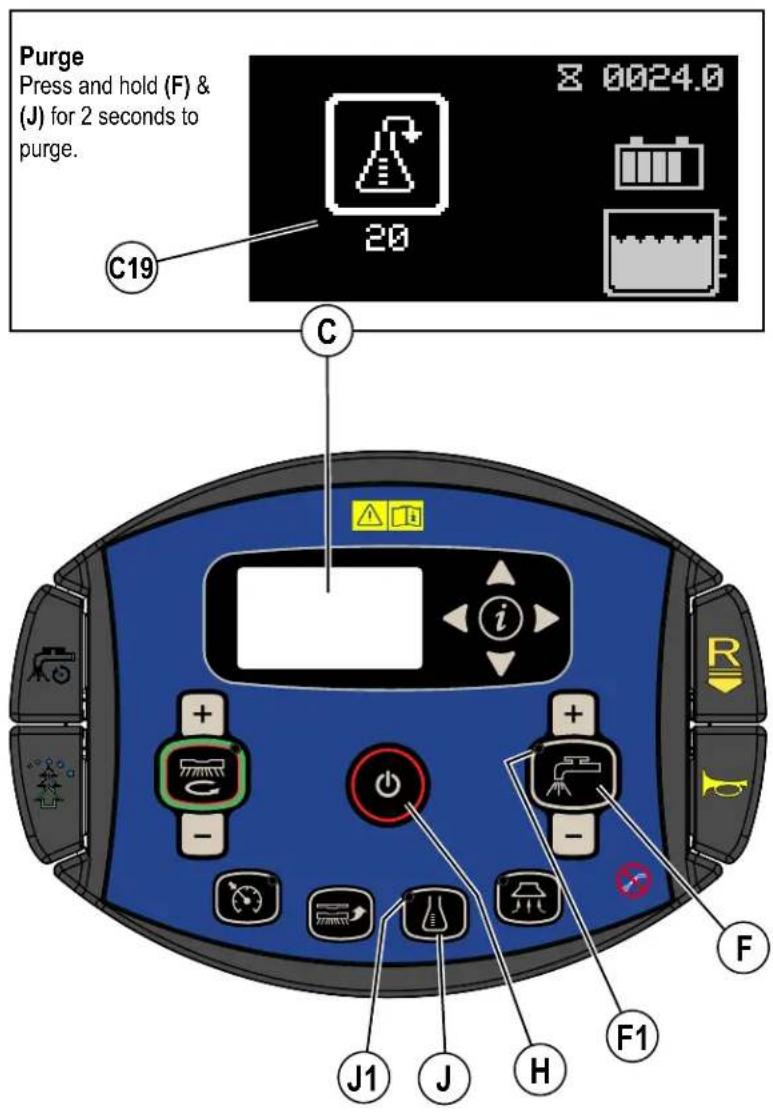
3 Press and hold the Solution Switch (F) and the Detergent Switch (J) down for 2 seconds. Release the switches when the Detergent Purge Indicator (C19) appears on the display (the Detergent Switch Light (J1) and Solution Switch Light (F1) will be ON). NOTE: Once activated the purge process takes 20 seconds. Press (F) or (J) again before 20 seconds to cancel purge. Normally one purge cycle is adequate to purge the system.
To Purge Weekly (SCRUB AND SOLUTION SYSTEMS MUST BE OFF):
1 Disconnect and remove the detergent cartridge. Install and connect a Cartridge filled with clean warm water.
2 Follow steps 2 and 3 from "To Purge When Changing Detergent".
When the detergent level is nearing the bottom of the cartridge it is time to refill or replace the cartridge.
SERVICE NOTE: Follow the "To Purge Weekly" instructions above if the machine is going to be stored for an extended period of time.
FIGURE 2-8
DETERGENT SYSTEM USE (ECOFLEX)
Detergent Use (SCRUB AND SOLUTION SYSTEM MUST BE ON): See Figure 2-9.
No detergent is dispensed until the scrub and detergent systems are enabled and the Drive Pedal (3) pushed forward.
• The Detergent Indicator (C6) will be displayed in scrub mode when the detergent system is installed on the machine.
• The Detergent Percentage Indicator (C7) will display the selected percentage when the detergent system is on.
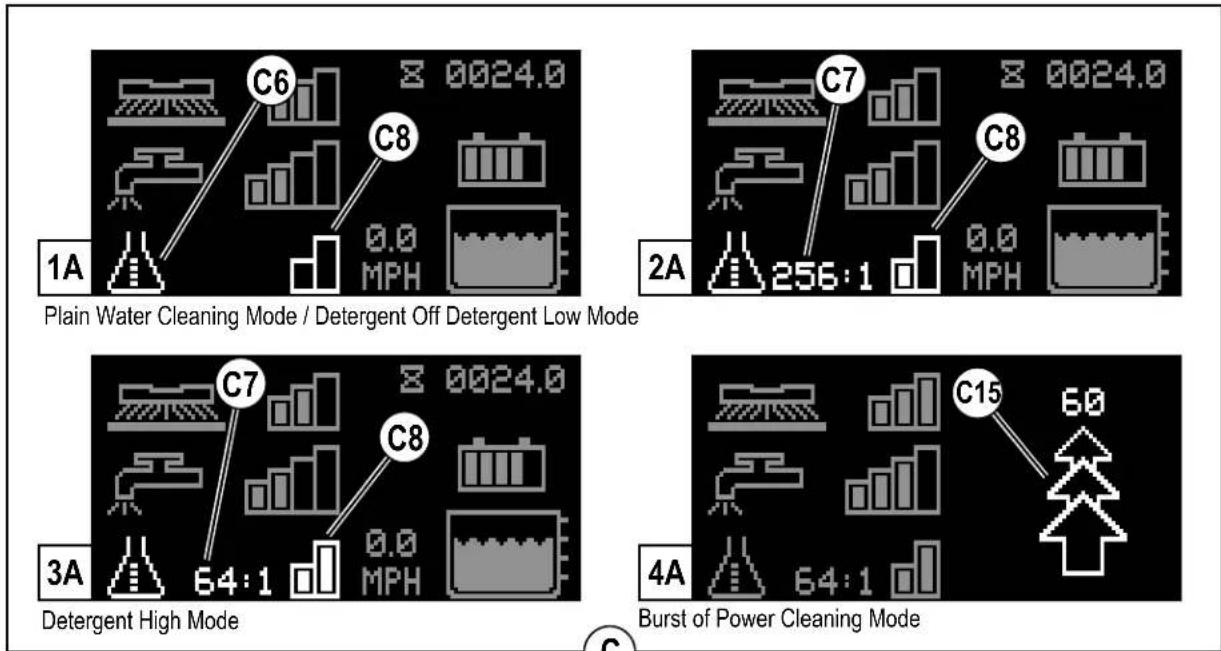
There are 4 modes of EcoFlex operation:
1A. Plain Water Cleaning Mode - During scrubbing, the detergent system can be turned off at any time by pressing the Detergent Switch (J) to allow scrubbing with water only. Detergent Percentage Indicator (C7) will be blank and Detergent Indicator Bar Graph (C8) will display no bars filled. Detergent Light (J1) will be off.
2A. Detergent Low Mode – Activated by pressing the Detergent Switch (J) when detergent is off (repeated presses will cycle to High Mode, off and back to low mode). Detergent Percentage Indicator (C7) will display the current low detergent level and Detergent Indicator Bar Graph (C8) will display first bar filled. Detergent Light (J1) will be on. See below the steps “To program the Detergent Low Level”.
3A. Detergent High Mode – Activated by pressing the Detergent Switch (J) when detergent is in low mode (repeated presses will cycle to off, low mode and back to high mode). Detergent Percentage Indicator (C7) will display the current high detergent level and Detergent Indicator Bar Graph (C8) will display left and right bars filled. Detergent Light (J1) will be on. See below the steps "To program the Detergent High Level".
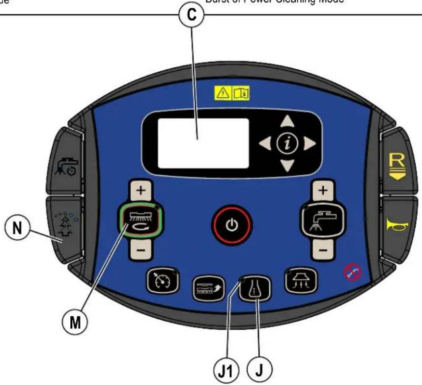
4A. Burst of Power Cleaning Mode – Push the Burst of Power Paddle (N) to increase the detergent ratio/percentage for one minute to the pre-programmed "high" detergent level (as noted in programming instructions below). Detergent system will be turned ON at "low" detergent level if it was off. This will also cause the solution flow rate to increase to the next level and the scrub pressure to increase to the next level. Burst of Power Indicator (C15) will blink for the duration of the Burst of Power process on the display along with a countdown timer. Push Paddle (N) again before countdown timer has expired to cancel Burst of Power. The amount of time Burst of Power runs is adjustable (see "Information Menu Display" submenu "Options").
To program the Detergent High Level
- Press the OneTouch™ Scrub switch (M) to activate the scrub system.
- Press and release Detergent Switch (J) until you have entered the detergent high mode ((C8) shows left and right bars filled).
- Press and hold the Detergent Switch (J) for approximately 2 seconds until the Percentage Indicator (C7) flashes.
- While the ratio/percentage is flashing, pressing and releasing the detergent switch will cycle through the available settings; Percentage = 0.3%, 0.4%, 0.5%, 0.66%, 0.8%, 1%, 1.5%, 2%, 3%, 3.8%
Ratio = 300:1, 256:1, 200:1, 150:1, 128:1, 100:1, 64:1, 50:1, 32:1, 26:1

CAUTION!
Do not use a concentration level exceeding the detergent manufacturer's recommendation.
- Once the desired level is displayed on the screen, stop and it will save the setting after 3 seconds.
- Whenever the high detergent setting is set to a lower concentration than the current programmed low setting, the low default setting will be equal to the high setting until changed by the operator.
To program the Detergent Low Level
- Press the OneTouch™ Scrub switch (M) to activate the scrub system.
- Press and release Detergent Switch (J) until you have entered the detergent low mode ((C8) shows left bar filled).
- Press and hold the Detergent Switch (J) for approximately 2 seconds until the Percentage Indicator (C7) flashes.
- While the ratio/percentage is flashing, pressing and releasing the detergent switch will cycle through the available settings (Note: only ratios/ percentages that are a lower concentration or equal to the high detergent setting will be available.
- Once the desired level is displayed on the screen, stop and it will save the setting after 3 seconds.
Once set, the detergent flow rate automatically increases and decreases with the solution flow rate, but the detergent ratio/percentage remains the same.
DETERGENT SYSTEM PREPARATION AND USE (ECOFLEX)
FIGURE 2-9
Be sure you understand the operator controls and their functions.
While on ramps or inclines, avoid sudden stops. Avoid abrupt sharp turns. Use low speed down ramps.
STARTING THE MACHINE
1 Follow the instructions in "Preparing the Machine for Use" section of this manual and verify the following;
- Batteries are fully charged.
- Exterior of machine is free of damage. Report any damage to your supervisor.
• Proper brushes is correctly installed. - Squeegee is installed.
- Solution tank is full.
- Recovery tank is empty.
- Ensure that area to be scrubbed is clear of obstacles that are not fixed, such as hoses, buckets or pails, boxes, electrical cords, carts, pallets, etc.

WARNING!
Do not dispense flammable cleaning agents, operate the machine on or near these agents, or operate in areas where flammable liquids exist.
2 Refer to illustrations on pages 8-11 if needed. Sit in the Operator's Seat (2), adjust the seat to a comfortable position using the Seat Adjustment Lever under the seat.
3 Place the Magnetic SmartKey (39) into the SmartKey Reader (22) on the machine. Press the Power Switch (H) to turn ON the machine.
4 Reference the Battery Indicator (C3). and Hour Meter (C1) before proceeding.
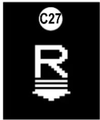
5 To transport the machine to the work area apply even pressure with your foot to the front of Drive Pedal (3) to go forward. For reverse, first press Reverse Paddle (D). Reverse Indicator (C27) will appear on the display then apply even pressure with your foot to the front of Drive Pedal (3). An audible alert will sound in reverse.
6 Adjust machine speed by varying the pressure on the Drive Pedal (3).

STOPPING THE MACHINE
1 Stop the machine by releasing the Drive Pedal (3).
2 After releasing the Drive Pedal the Brake Pedal (40) can be pressed to help stop the machine.
3 ONLY IN THE EVENT OF AN EMERGENCY!
To stop all machine functions immediately, press the Emergency Stop (A).
• The display will show Emergency Stop Activated Indicator (C20).
- To reset the machine functions, rotate the emergency stop clockwise.
OPERATING THE MACHINE - CONTINUED

WARNING!
Be sure you understand the operator controls and their functions.
While on ramps or inclines, avoid sudden stops when loaded. Avoid abrupt sharp turns. Use low speed down hills.
To Scrub...
Follow the instructions in "Starting the Machine" section and drive the machine to the start point for cleaning.
1 See Figure 3-1. Press the One-Touch Scrub ON Switch (M) once for Regular Scrub. Press the Scrub Pressure Increase Switch (M+) once for Heavy Scrub or twice for Extreme Scrub mode. The solution flow has settings that coincide with the scrub pressure, it will increase and decrease along with the scrub pressure.
NOTE: The solution flow rate can also be increased or decreased independently of the scrub pressure by pressing the Solution Flow Increase Switch (F+) or Solution Flow Decrease Switch (F-), observe the Solution Flow Rate Bar Graph (C10). Any subsequent scrub pressure adjustments will reset the solution flow rate to default.
2 When the One-Touch Scrub ON Switch (M) is selected, the brushes and squeegee are automatically lowered to the floor. The scrub, solution, vacuum and detergent (EcoFlex models) systems are all automatically enabled and will start when the Drive Pedal (3) is activated. Any individual system can be turned OFF or back ON by simply pressing its switch at any time during scrubbing.
NOTE: When operating the machine in reverse the squeegee automatically raises.
Detergent: See "Detergent System Preparation and Use (EcoFlex) for detailed information regarding adjustment and use.
3 Begin scrubbing by driving the machine forward in a straight line at a normal walking speed and overlap each path by 2-3 inches (50-75 mm). Adjust the machine speed and solution flow when necessary according to the condition of the floor. Push the Timed Solution Off Paddle (O) before entering a turn to temporarily turn off the solution flow. The Solution Flow Rate Bar Graph (C10) will be replaced by a 5 second countdown timer showing how long the solution flow will be off. Push paddle again before timer runs out to cancel solution off.
NOTE: While scrubbing the maximum machine speed can be set by pressing the Speed Limiter Switch (L). Adjust the machine to the desired speed using the Drive Pedal (3) then press the Speed Limiter Switch (N). The operator can now press the pedal all the way forward without increasing the machine speed thereby reducing operator fatigue. The machine Speed (C5) is shown on the display. The speed limit will be in effect every time you scrub until the speed limiter switch is pressed again (while scrubbing) to disable the speed limit.

CAUTION!
To avoid damaging the floor, keep the machine moving while the brushes are turning.
4 When scrubbing, check behind the machine occasionally to see that all of the waste water is being picked up. If there is water trailing the machine, you may be dispensing too much solution, the recovery tank may be full, or the squeegee tool may require adjustment.
5 For extremely dirty floors, a one-pass scrubbing operation may not be satisfactory and a "double-scrub" operation may be required. This operation is the same as a one-pass scrubbing except on the first pass the squeegee (33) and scrub deck blades (AA) are in the up position see Side Blade - Double Scrub Position. Press the Vacuum Switch (G) to raise the squeegee.
This allows the cleaning solution to remain on the floor to work longer. The final pass is made over the same area, with the squeegee and side blades lowered to pick up the accumulated solution
6 The recovery tank has a Shutoff Float (25). When the tank is full the float is activated and closes the inlet so no more water can enter the recovery tank. When the float is activated the operator may notice a change in the sound of the vacuum motor or will notice machine is no longer picking up water. When the shutoff float is activated, the recovery tank must be emptied. The machine will not pick up water with the float activated but no machine functions will turn off.
7 When the operator wants to stop scrubbing or the recovery tank is full, press the One-Touch Scrub Switch (M) once. This will automatically stop the scrub brushes and solution flow and the scrub deck will raise up. The squeegee will raise up after a brief delay and the vacuum will stop after an additional delay (this is to allow any remaining water to be picked up without turning the vacuum back on). When scrub is turned off the speed limit is also turned off and machine speed will go back to normal operation.
8 Drive the machine to a designated waste water "DISPOSAL SITE" and empty the recovery tank. To empty, pull the Recovery Tank Drain Hose (28) from its storage area. Hold the end of the hose above the water level in the tank then unscrew the cap. Squeeze the hose as shown until the hose is near the drain to avoid sudden uncontrolled flow of waste water. Screw on the cap and push the recovery tank drain hose back into its storage area. Refill the solution tank and continue scrubbing.
NOTE: Make sure the Recovery Tank Cover (24) and the cap on the Recovery Tank Drain Hose (28) are properly seated or the machine will not pick-up water correctly.
If the batteries become discharged to the low voltage cutout threshold the Battery Low Voltage Indicator (C14) will come on, the scrub brushes and solution flow will stop and the scrub deck will raise up. The squeegee will raise up after a brief delay and the vacuum will stop after an additional delay. Transport the machine to a service area. Recharge the batteries according to the instructions in "Charging Wet Batteries" or "Charging Gel/AGM (VRLA) Batteries" sections of this manual.
OPERATING THE MACHINE - CONTINUED
FIGURE 3-1
WET VACUUMING
Steps to follow in fitting the machine with optional attachments for wet vacuuming.
1 Disconnect the recovery hose (29) from the squeegee mount. Connect the coupler and hose from the wand kit to the recovery hose.
2 Attach suitable wet pick-up tools to the hose. (An optional Vac Wand Kit PN56116355 is available from Nilfisk).
3 Place the magnetic SmartKey onto the SmartKey Reader (22) and press the Power Switch (H). While standing alongside the machine (not on the seat) press the Vacuum Switch (G). The vacuum motor will run continuously until the switch is pressed again to turn it OFF. The Wand Indicator (C17) is displayed. NOTE: Pressing the Vacuum Switch (G) while seated on the machine will cause the squeegee to lower and the vacuum motor(s) to run while machine is moving forward. The Vacuum Indicator (C16) will be displayed.
AFTER USE
1 When finished scrubbing, press the One-Touch Scrub Switch (M). This will automatically raise, retract and stop all the machine systems (brush, squeegee, vacuum, solution and detergent (EcoFlex models)). Then drive the machine to a service area for daily maintenance and review of other needed service up keep.
2 To empty the solution tank, remove the Solution Drain Hose (13) from its storage clamp under the front bumper of the machine. Direct the hose to a designated "DISPOSAL SITE" and remove the plug. Rinse the tank with clean water.
3 To empty the recovery tank, pull the Recovery Tank Drain Hose (28) from its storage area. Hold the end of the hose above the water level in the tank then unscrew the cap. The Recovery Tank Drain Hose can be squeezed to regulate the flow and avoid sudden, uncontrolled flow of waste water. Rinse the recovery tank with clean water. Inspect the recovery and vacuum hoses; replace if kinked or damaged.
4 Remove the brushes or pad holders. Rinse the brushes or pads in warm water and hang up to dry.
5 Remove the squeegee, rinse it with warm water and re-install on mount or hang it from the back of the recovery tank.
6 Remove the hopper on cylindrical systems and clean thoroughly. Remove from either side of the machine by tilting the hopper up and away from housing, then pull out.
7 Check the maintenance schedule below and perform any required maintenance before storage.
8 Store the machine indoors in a clean dry place. Keep from freezing. Leave the tanks open to air them out.
9 Turn the machine off by pressing the Power Switch (H) and then remove the magnetic key.
10 Batteries are the most expensive replacement item on this machine. To protect your investment and to get as many cycles from the batteries as possible, remember the following:
- Batteries will last longer if kept fully charged.
- Batteries equipped with this machine will not develop a memory.
- Batteries will last longer and will deliver more cycles if they are opportunity charged.
- Battery chargers will not over or undercharge the batteries.
- Batteries will prematurely fail if stored in a discharged state.
- Every day after use, the battery charger must be plugged in and the charger must be allowed to run through a full charging sequence to fully charge the batteries.
MAINTENANCE
MAINTENANCE SCHEDULE
| MAINTENANCE ITEM Daily Weekly Monthly Yearly | ||||
| Charge Batteries X | ||||
| Check/Clean Tanks & Hoses X | ||||
| Check/Clean/Rotate the Brushes/Pads X | ||||
| Check/Clean the Squeegee X | ||||
| Empty/Clean Debris Catch Tray in Recovery Tank X | ||||
| Check/Clean the vacuum motor foam filter(s) X | ||||
| Clean Hopper on Cylindrical System X | ||||
| Clean the surface of the Magnetic SmartKey Reader (22) | X | |||
| Check Each Battery Cell(s) Water Level (wet batteries) | X | |||
| Inspect Scrub Deck Blades | X | |||
| Inspect and clean Solution Filter | X | |||
| Clean Solution Trough on Cylindrical System | X | |||
| Purge Detergent System (EcoFlex only) | X | |||
| * Clean Solution Tank | X | |||
| Lubrication – see “Lubricating the Machine” | X | |||
| ** Check Carbon Brushes | X | |||
* Cleaning the solution tank is only needed if you use a mixture of water and cleaning detergent within the tank.
** Have Nilfisk check the carbon brushes for; vacuum motor(s) after 1200 recovery hours (replace motor(s) after 2000 recovery hours), scrub motors (disc & cylindrical) after 1200 scrub hours.
NOTE: Refer to the Service Manual for more detail on maintenance and service repairs.
CLEANING RECOVERY TANK
1 Drive the machine to the appointed disposal area.
2 Ensure that the machine is off and the SmartKey (39) is removed.
3 Pull the Recovery Tank Drain Hose (28) from its storage area.
4 Direct the hose to a designated "DISPOSAL SITE" and unscrew the cap (hold the end of the hose above the water level in the tank to avoid sudden, uncontrolled flow of waste water). The Recovery Tank Drain Hose can be squeezed to regulate the flow.
5 Lift open the Recovery Tank Cover (24).
6 Rinse the recovery tank out thoroughly to remove any and all debris from the tank. To clean out the recovery tank leave the drain hose open to a floor drain and spray the inside of the tank clean with a hose. A hose with a spray attachment can be used to spray out the recovery tank but should not be directed onto the Vacuum Motor Filter Housing (26). Do not allow sprayed water to splash outside of tank or into the vacuum motor inlet.
NOTE: The spray hose should not be used to clean the exterior of the machine near the operator control panel to prevent water ingress into sensitive electronics.
7 Remove the Debris Catch Tray (27) from the recovery tank. Empty and rinse the debris catch tray then reinstall it.
8 Open the Vacuum Motor Filter Housing (26) and remove the filter. Remove any debris that has gathered inside the filter housing. Rinse the filter then reinstall.
9 Check the condition of the recovery tank cover gasket and the area it seats against. They should be clean to create a good seal.
NOTE: The gasket allows the creation of a vacuum in the tank, which is necessary to vacuum up the recovery water.
10 Close the recovery tank cover. NOTE: The cover can be left open to air out the tank between uses.
CLEANING SOLUTION FILTER
1 Drive the machine to the appointed disposal area.
2 Ensure that the machine is off and the SmartKey (39) is removed.
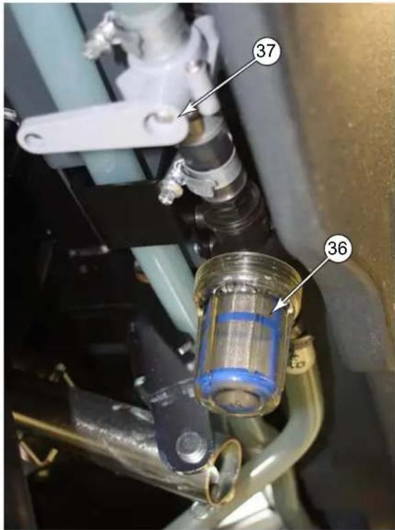
3 Close the Solution Shutoff Valve (37) by rotating the handle 90° so it's pointed at the right side of the machine (Figure 4-1 shows handle in the closed position).
4 Unscrew the solution filter cover (36). There will likely still be some solution in the line that will spill out.
5 Clean the filter cover and screen.
6 Reinstall the screen and cover, ensure the gasket is in place.
7 Open the Solution Shutoff Valve (37).
FIGURE 4-1
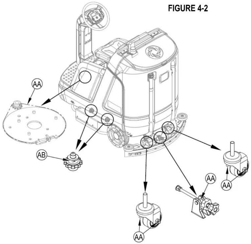
LUBRICATING THE MACHINE
Once a month, pump a small amount of grease into each grease fitting on the machine until grease seeps out around the bearings. See Figure 4-2.
Grease fitting locations (or apply grease to) (AA):
• Squeegee Caster Wheel Axle and Pivot
- Steering Chain
- Squeegee mount angle adjustment knob threads
Once a month, apply light machine oil or synthetic lubricant spray to lubricate (AB):
- Side Blade Down Stop Adjustment Threads
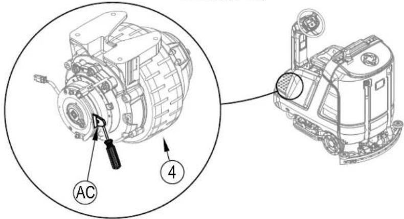
ELECTROMAGNETIC BRAKE
CAUTION!
To avoid uncontrolled machine movement, block the wheels and ensure machine is on a level surface before disengaging the electromagnetic brake.
See Figure 4-3. The Drive Wheel Assembly (4) has a built in electromagnetic brake that is engaged whenever the machine power is OFF or the Drive Pedal (3) is not being pressed. This brake can be manually overridden if necessary by inserting a medium to large screwdriver behind the Yoke (AC) as shown. This should only be done in the event you need to push or pull the unit a short distance.
FIGURE 4-3
CHARGING WET BATTERIES
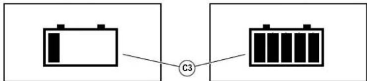
Charge the batteries each time the machine is used or when the Battery Charge Level Indicator (C3) is reading less than full.
WARNING!
Do not top off the batteries before charging. Check to ensure the plates are covered only.
Charge batteries in a well-ventilated area. If battery acid makes contact with your skin, flush the affected area with water for 5 minutes and seek medical attention. FIGURE 4-4
Do not smoke while servicing the batteries.
When Servicing Batteries...
* Remove all jewelry
* Do not smoke
* Wear safety glasses, rubber gloves and a rubber apron
* Work in a well-ventilated area
* Do not allow tools to touch more than one battery terminal at a time
* ALWAYS disconnect the negative (ground) cable first when replacing batteries to prevent sparks.
* ALWAYS connect the negative cable last when installing batteries.
If your machine shipped with an onboard battery charger do the following:
1 Turn the machine off at the Power Switch (H).
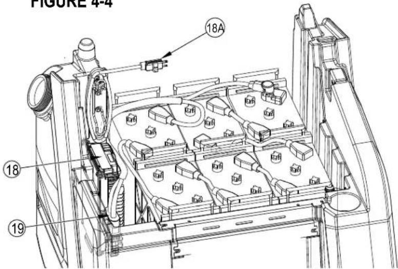
2 See Figure 4-4. Tip the seat forward (gas spring holds the seat open) for battery, charger access and proper ventilation.
3 Unwind the electrical cord (18A) for the onboard charger and plug it into a properly grounded outlet. Refer to the OEM product manual for more detailed operating instructions. While AC power is applied to the onboard charger all machine functions are disabled.
FIGURE 4-4
flowchart
graph LR
    A[" "] --> C[" "]
    C --> D[" "]
    style A fill:#f9f,stroke:#333
    style D fill:#bbf,stroke:#333
4 The Battery Charge Status Indicator (C3) will begin showing the batteries' state of charge. This indicates that the charging cycle has begun. As the charging cycle continues, the battery charge level will fill in.
5 When the Battery Charge Status Indicator (C3) is completely filled, the machine senses fully charged batteries, however the charging process may not be complete. Rely on the status lights on the Charger (18) (and its OEM manual) to verify when the batteries are completely charged. This may take several hours depending upon the condition of the batteries before charging.
6 After charging is complete unplug the charger and wind up the Cord (18A). Wait at least 10 seconds before turning on the machine after unplugging the charger.
If your machine shipped without an onboard battery charger do the following:
1 Turn the machine off at the Power Switch (H).
2 See Figure 4-4. Tip the seat forward for battery access and proper ventilation, gas spring holds seat open.
3 Disconnect the batteries from the machine and push the connector from the charger into the Machine Battery Connector (19). Follow the instructions on the battery charger and OEM product manual. SERVICE NOTE: Make sure you plug the battery charger into the connector that attaches to the batteries.
CAUTION!
To avoid damage to floor surfaces, wipe water and acid from the top of the batteries after charging. Under or overcharging will shorten battery life and limit performance. Be sure to FOLLOW PROPER CHARGING INSTRUCTIONS!
CHECKING THE BATTERY WATER LEVEL
Check the water level of the batteries at least once a week.
Remove the vent caps and check the water level in each battery cell. Use distilled or demineralized water in a battery filling dispenser (available at most auto parts stores) to fill each cell to the level indicator (or to .39 inches / 10 mm over the top of the separators). DO NOT over-fill the batteries!
CAUTION!
Acid can spill onto the floor if the batteries are overfilled.
Tighten the vent caps. Wash the tops of the batteries with a solution of baking soda and water (2 tablespoons of baking soda to 1 liter of water).
CHARGING GEL/AGM (VRLA) BATTERIES
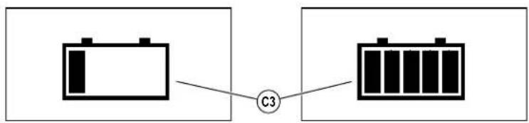
Charge the batteries each time the machine is used or when the Battery Charge Level Indicator (C3) is reading less than full.
WARNING!
Charge batteries in a well-ventilated area. If battery acid makes contact with your skin, flush the affected area with water for 5 minutes and seek medical attention.
Do not smoke while servicing the batteries.
FIGURE 4-4
When Servicing Batteries...
* Remove all jewelry
* Do not smoke
* Wear safety glasses, rubber gloves and a rubber apron
* Work in a well-ventilated area
* Do not allow tools to touch more than one battery terminal at a time
* ALWAYS disconnect the negative (ground) cable first when replacing batteries to prevent sparks.
* ALWAYS connect the negative cable last when installing batteries.
CAUTION!
Your valve regulated lead acid (VRLA) battery will deliver superior performance and life ONLY IF IT IS RECHARGED PROPERLY! Under or overcharging will shorten battery life and limit performance. Be sure to FOLLOW PROPER CHARGING INSTRUCTIONS! DO NOT ATTEMPT TO OPEN THIS BATTERY! If a VRLA battery is opened, it loses its pressure and the plates become oxygen contaminated. THE WARRANTY WILL BE VOIDED IF THE BATTERY IS OPENED.
flowchart
graph LR
    A[" "] --> C[" "]
    C --> D[" "]
    style A fill:#fff,stroke:#000
    style D fill:#fff,stroke:#000
    classDef box1 stroke:#000,stroke-width:2px;
    classDef box2 stroke:#000,stroke-width:2px;
    classDef box3 stroke:#000,stroke-width:2px;
    class A,B,C box1;
If your machine shipped with an onboard battery charger do the following:
1 Turn the machine off at the Power Switch (H).
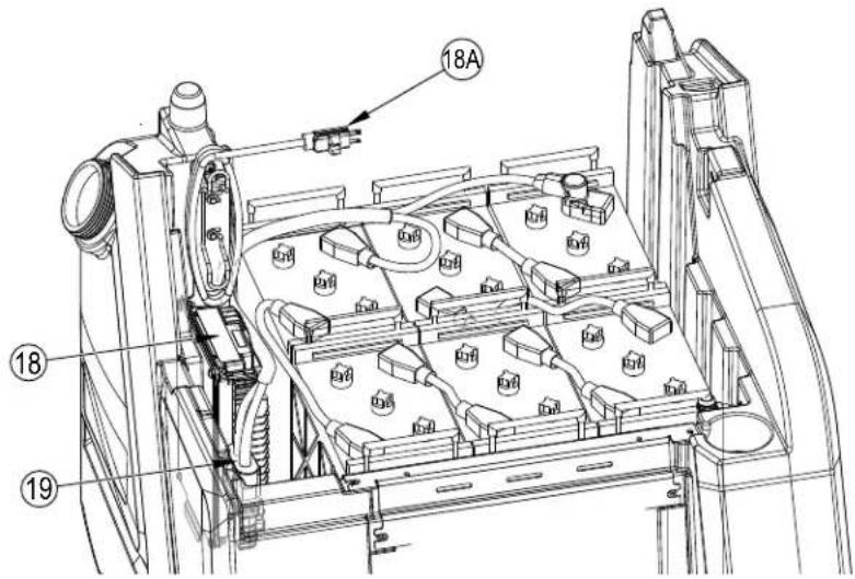
2 See Figure 4-4. Tip the seat forward for battery, charger access and proper ventilation, gas spring holds the seat open.
3 Unwind the electrical cord (18A) for the onboard charger and plug it into a properly grounded outlet. Refer to the OEM product manual for more detailed operating instructions. While AC power is applied to the onboard charger all machine functions are disabled.
4 The Battery Charge Status Indicator (C3) will begin showing the batteries' state of charge. This indicates that the charging cycle has begun. As the charging cycle continues, the battery charge level will fill in.
5 When the Battery Charge Status Indicator (C3) is completely filled, the machine senses fully charged batteries, however the charging process may not be complete. Rely on the status lights on the Charger (18) (and its OEM manual) to verify when the batteries are completely charged. This may take several hours depending upon the condition of the batteries before charging.
6 After charging is complete unplug the charger and wind up the Cord (18A). Wait at least 10 seconds before turning on the machine after unplugging the charger.
If your machine shipped without an onboard battery charger do the following:
1 Turn the machine off at the Power Switch (H).
2 See Figure 4-4. Tip the seat forward for battery access and proper ventilation, gas spring holds the seat open.
3 Disconnect the batteries from the machine and push the connector from the charger into the Machine Battery Connector (19). Follow the instructions on the battery charger and OEM product manual. SERVICE NOTE: Make sure you plug the battery charger into the connector that attaches to the batteries.
IMPORTANT: Make sure you have an appropriate charger for use on Gel cell batteries. Use only "voltage-regulated" or "voltage-limited" chargers. Standard constant current or taper current chargers MUST NOT be used. A temperature-sensing charger is recommended, as manual adjustments are never accurate and will damage any VRLA battery.
If the squeegee leaves narrow streaks or water, the blades may be dirty or damaged. Remove the squeegee, rinse it under warm water and inspect the blades. Reverse or replace the blades if they are cut, torn, wavy or worn.
To Reverse or Replace the Rear Squeegee Wiping Blade...
1 See Figure 4-5. Raise the squeegee tool off the floor, then unsnap the Latch (AA) on the squeegee tool.
2 Remove the Tension Strap (AB).
3 Slip the Rear Blade (AJ) off the alignment pins.
4 The squeegee blade has 4 working edges as shown below. Turn the blade so a clean, undamaged edge faces toward the front of the machine. Replace the blade if all 4 edges are nicked, torn or worn to a large radius.
5 Install the blade, following the steps in reverse order and adjust the squeegee tilt.
To Reverse or Replace the Front Squeegee Blade...
1 Raise the squeegee tool off the floor, then loosen the (2) Thumb Nuts (31) on top of the squeegee and remove the squeegee tool from the mount (AG).
2 Loosen the Front Squeegee Blade Removal Thumb Nut (AC), then remove Tension Strap (AD) and Front Blade (AK).
3 The squeegee blade has 4 working edges as shown below. Turn the blade so a clean, undamaged edge faces toward the front of the machine. Replace the blade if all 4 edges are nicked, torn or worn to a large radius.
4 Install the blade, following the steps in reverse order and adjust the squeegee tilt/angle.
SQUEEGEE ADJUSTMENT
There are two squeegee tool adjustments possible, tilt and height.
Adjust the squeegee tilt whenever a blade is reversed or replaced, or if the squeegee is not wiping the floor dry.
1 Park the machine on a flat, even surface.
2 Lower the squeegee, move the machine ahead slightly and adjust the squeegee tilt and height using the Squeegee Tilt Adjust Knob (30) and Squeegee Caster Lock Knobs (32) so that the rear squeegee blade touches the floor evenly across its entire width and is bent over slightly as shown in the squeegee cross section.
3 Squeegee height is pre-set at the factory but may require periodic adjustment due to caster wear. Proper squeegee height is achieved when the rear squeegee blade touches the floor evenly across its entire width and is bent over slightly with the caster wheel just touching the floor.
a. Loosen Caster Lock Knobs (32).
b. Thread Casters (AE) up or down as required to achieve proper height and ensure blade position is uniform left to right.
c. Tighten Caster Stops (AF) against squeegee mount (AG).
d. Tighten Squeegee Caster Lock Knobs (32) against squeegee mount to lock adjustment.
4 The Tilt Adjust Knob (30) is used to adjust the tool tilt/angle for uniform contact from center to tips of blade.
a. Loosen Tilt Stop Knob (AH).
b. Turn Tilt Adjust Knob as required to adjust.
c. Tighten Tilt Stop Knob (AH) against the squeegee mount to lock adjustment.
SQUEEGEE MAINTENANCE - CONTINUED
FIGURE 4-5
The side blades' function is to channel the waste water to the squeegee, helping contain the water within the machines cleaning path. During normal use the blades will wear in time. The operator will notice a small amount of water leaking out underneath the side blades. A height adjustment can easily be made to lower the blades so that all the water can be picked up by the squeegee.
DISC - To reverse or replace the scrub system side blades ...
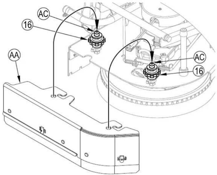
1 See Figure 4-6. Loosen the two Side Blade Assembly Removal Knobs (16) (2 per side) and pull the Side Blade Assembly (AA) slightly forward and then off the scrub deck.
2 Loosen the two Thumb Nuts (AL) then rotate the two Retainers (AB) to be horizontal and separate the blade from the retainer strap.
3 The main side blade has 4 working edges as shown. Turn the blade so a clean, undamaged edge faces toward the center of the machine. Replace the blades as a set if all edges are nicked, torn or worn beyond their ability to be adjusted.
4 Reinstall the blade onto the blade assembly and secure with Retainers (AB) by rotating back to the vertical position and tighten Thumb Nuts (AL). Adjust the blade height for proper contact to the floor when the brush deck is placed in the scrub position. See "Side Blade Height Adjustment" section.
CYLINDRICAL - To reverse or replace the scrub system side blades ...
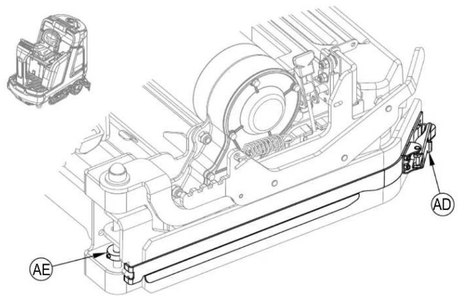
1 See Figure 4-7. Unlatch the retaining strap (AD) and remove the strap and blade.
2 The main side blade has 4 working edges as shown. Turn the blade so a clean, undamaged edge faces toward the center of the machine. Swap the right and left side blades to use the remaining two edges. Replace the blades as a set if all edges are nicked, torn or worn beyond their ability to be adjusted.
3 Reinstall the blade onto the blade assembly and secure by latching the retainer strap (AD). Adjust the blade for proper contact to the floor when the brush deck is placed in the scrub position. See "Side Blade Height Adjustment" section.
SIDE BLADE HEIGHT ADJUSTMENT
DISC -
1 See Figure 4-6. The side blade assembly knob removal screw studs have leveling Adjuster Collars (AC), that are to be raised or lowered to compensate for blade wear.
2 Make sure the machine is on a level surface.
3 Lower the scrub deck by pressing the One-Touch Scrub Switch (M) and drive the machine forward a short distance to ensure the blades fold over.
4 Observe blade fold over.
5 The side blade Removal Knobs (16) can be loosened with assembly left on and the Adjuster Collars (AC) rotated by reaching under the blade assembly.
6 Turn the Adjuster Collars (AC) (Up or Down) to where the blades just fold over enough when scrubbing that all the waste water is contained inside the scrub deck.
Note: Make small adjustments to obtain good blade wiping. Do not lower the blades too much to where they fold over excessively and cause unneeded blade wear.
CYLINDRICAL -
1 See Figure 4-7. Each side blade assembly has a Down Stop (AE), that can be raised or lowered to compensate for blade wear.
2 Make sure the machine is on a level surface.
3 Lower the scrub deck by pressing the One-Touch Scrub Switch (M) and drive the machine forward a short distance to ensure the blades fold over.
4 Observe blade fold over.
5 Loosen the Down Stop (AE) and adjust (Up or Down) to where the blades just fold over enough when scrubbing that all waste is contained inside the scrub deck.
Note: Make small adjustments to obtain good blade wiping. Do not lower the blades too much to where they fold over excessively and cause unneeded blade wear.
SIDE BLADE MAINTENANCE - CONTINUED
FIGURE 4-6
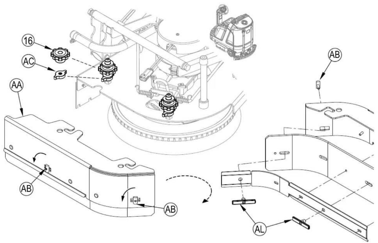
FIGURE 4-7
SIDE BLADE PRESSURE ADJUSTMENT - CYLINDRICAL ONLY
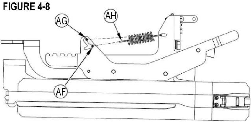
1 The cylindrical scrub deck side blades have two settings for down pressure. See Figure 4-8.
2 Position 1 (AF) is normal wiping pressure, it is recommended to start at this setting.
Position 2 (AG) is heavy wiping pressure, this setting can be used if wiping performance is not satisfactory. NOTE: Position 2 will cause faster blade wear.
3 Pull the end of Spring (AH) and move between the two settings. Use the same setting on both sides of the scrub deck.
1 See Figure 4-9. Loosen Side Blade Assembly Removal Knobs (16) and remove the Side Blade Assemblies (AA).
2 Place the Blade Assemblies (AA) onto the Blade Assembly Holders (AC) at the round holes in the blade assemblies. Repeat for blade assembly on the other side of the scrub deck.
3 When finished double scrubbing with the machine, reinstall Side Blade Assemblies into their normal operating position and tighten Removal Knobs (16).
FIGURE 4-9
CYLINDRICAL -
1 See Figure 4-10. Lift up on Blade Raise/Lower Lever (AJ) to raise blade. While holding the lever in the raised position, rotate and engage the Latch (AK).
2 When finished double scrubbing with the machine, lift up on Raise/Lower Lever (AJ) again and disengage the Latch (AK) and lower side blade back to its normal operating position.
FIGURE 4-10
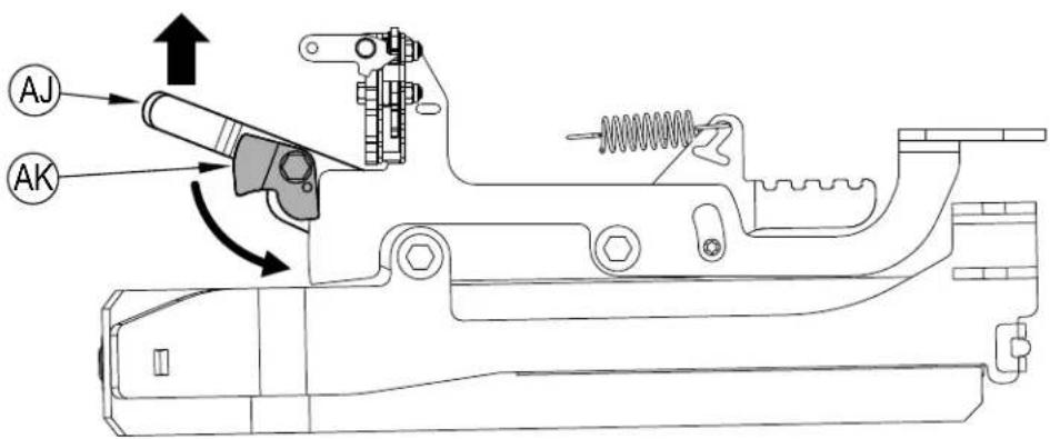
Left Side Blade Assembly shown raised in the double scrub position, inside view for clarity.
TROUBLESHOOTING
GENERAL MACHINE TROUBLESHOOTING
| Problem Possible Cause Remedy | ||
| Poor water pick-up | Worn or torn squeegee blades Reverse or replace | |
| Squeegee out of adjustment Adjust so blades touch floor or evenly across entire width | ||
| Recovery tank full Empty recovery tank | ||
| Recovery tank drain hose leak Secure drain hose cap or replace | ||
| Recovery tank cover gasket leak | Clean gasket and sealing surface / Replace gasket if damaged / Seat cover properly | |
| Debris caught in squeegee Clean squeegee tool | ||
| Squeegee seal clogged or missing Clean or replace squeegee seal | ||
| Vacuum hose clogged Remove debris | ||
| Using too much solution Reduce flow via control panel solution button | ||
| Foam filter cover not seated Seat cover properly | ||
| Poor scrubbing performance | Worn brush or pad Rotate or replace brushes | |
| Wrong brush or pad type | Consult Advance Authorized Service Center | |
| Wrong cleaning chemical | Consult Advance Authorized Service Center | |
| Moving machine too fast | Slow down | |
| Not using enough solution | Increase flow via control panel solution button | |
| Inadequate solution flow or no solution | Solution tank empty | Fill solution tank |
| Solution lines, valves, filter or trough clogged | Flush lines, trough and clean solution filter | |
| Solution turned OFF | Activate solution flow via control panel switch (F) | |
| Rotate Solution Shutoff Valve (37) to ON | ||
| Solution solenoid valve plugged or defective | Clean or replace valve(contact Advance Authorized Service Center) | |
| Machine does not power ON | Machine Battery Connector (19) disconnected | Reconnect battery connectors |
| Tripped 70 Amp circuit breaker (10a) | Check for electrical short circuit & reset | |
| Blown Main Fuse 150 Amp Replace Main Fuse 150 Amp | ||
| No FWD/REV wheel drive | Seat switch open | Sit on the seat to close seat switch |
| Drive system speed controller | Check error fault codes(contact Advance Authorized Service Center) | |
| Emergency Stop Switch (A) activated, display will show Emergency Stop Activated Indicator (C20). | Reset Emergency Stop Switch | |
| Poor Sweeping Performance (Cylindrical System) | Hopper Full | Empty and clean hopper |
| Brushes worn | Replace brushes | |
| Bristles have taken a set | Rotate brushes | |
| No Detergent Flow (EcoFlex models only) | Empty detergent cartridge | Fill detergent cartridge |
| Plugged or kinked detergent flow line | Purge system, straighten lines to remove any kinks | |
| Dry seal cap on detergent cartridge not sealed | Reseat dry seal cap | |
| Detergent pump failure | Check pump, wiring and lines | |
| Magnetic SmartKey Errors | No Key Indicator (C21).-No Magnetic SmartKey is present on the SmartKey Reader (22). | Place an appropriate SmartKey onto the SmartKey Reader. |
| Clean both the SmartKey and the SmartKey Reader using a clean cloth. Depress the SmartKey between your thumb and forefinger to insure free movement of the magnet. | ||
| Key Read Error Indicator (C22).- Magnetic SmartKey present on the SmartKey Reader (22) cannot be read. | Clean both the SmartKey and the SmartKey Reader using a clean cloth. Depress the SmartKey between your thumb and forefinger to insure free movement of the magnet. | |
| Restricted User Key Indicator (C23).-Magnetic SmartKey present on the SmartKey Reader (22) is not programmed to be used with this machine. | Place a SmartKey that has been programmed to be used with this machine onto the SmartKey Reader. | |
GENERAL MACHINE TROUBLESHOOTING
FAULT CODE DISPLAY
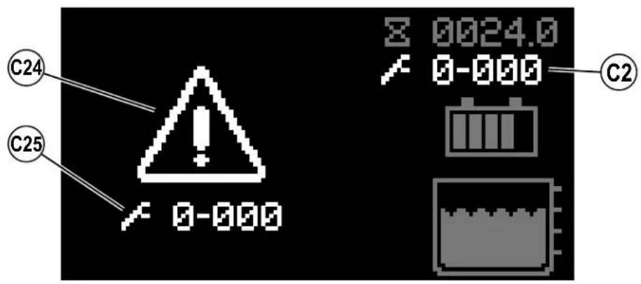
Any fault codes detected by the controllers will be displayed on the control panel display as they occur see Figure 5-1. If more than one error exists, the display will sequence through the error codes at one-second intervals. The error will display as a mechanical wrench symbol followed by a four-digit code.
Fault codes are displayed as X-YYY, where
X = system number (1: main board, 2: power module, 3: drive controller)
YYY = fault code number
For example, 1-101 would be solution solenoid valve – short.
C2 Active Fault Code
C24 Critical Fault Indicator
C25 Fault Code (Critical)
FIGURE 5-1
FAULT CODE HISTORY
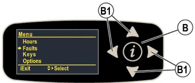
Every fault code that occurs is recorded by the machine and kept in a history log. See Figures 5-2 - 5-4. To view the fault history press the Information Switch (B) to bring up the information menu. Use the four Navigation Arrows (B1) (up, down, left & right) to move through the menu and the information switch to exit the menu.
FIGURE 5-2
Scroll down to Faults, right arrow to select.
Menu [Menu]
Hours [Hours]
Faults [Faults]
Keys [Keys]
Options [Options]
Exit [i Exit]

Select [Select]
flowchart
graph TD
    A["Menu"] --> B["Hours"]
    B --> C["Faults"]
    C --> D["Keys"]
    D --> E["Options"]
    E --> F["iExit"]
    F --> G["Select"]
    H["B1"] --> I["i"]
    I --> J["B"]
    I --> K["B1"]
Scroll down to Fault History, right arrow to select.
▶ Faults [Faults]
Active Faults [Active Faults]
Fault History [Fault History]
Back [Back] Select [Select]
FIGURE 5-3
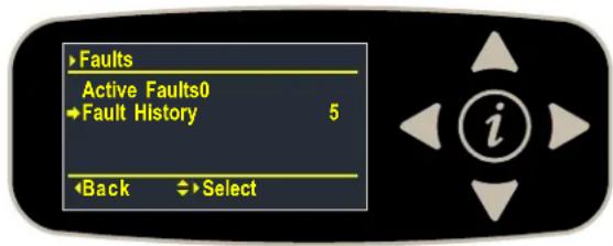
Each fault is displayed along with; (Nx) where "N" is the number of times the fault has occurred, the timestamp shows the most recent occurrence and description. Use the up and down arrows to scroll through the list of faults.
▶ Fault History [Fault History]
Fault Code (Nx) Drive Hours
Fault Code Description
Back [Back] Scroll [Scroll]
FIGURE 5-4
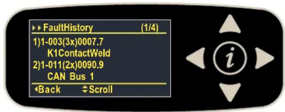
SPECIFICATIONS
ACCESSORIES / OPTIONS
In addition to the standard components, the machine can be equipped with the following accessories/options, according to the machine specific use:
| Brushes with harder or softer bristles Operator Foot Guard Kit | |
| Squeegee and side blades with different material Scrub-N-Vac Tool Kit | |
| Dual Vacuum Motor Kit Vacuum Wand Kit | |
| Blue Light Kit Headlight Kit | |
| Standard Seat Kit Squeegee Guard Kit | |
| Overhead Guard Kit Arm Rest Kit | |
| Seat Belt Kit EcoFlex Kit | |
| Battery Watering Kit Heavy Duty Front Bumper Kit | |
| Wash Hose Kit Mop Holder Kit | |
| Onboard Charger Kit Drain Hose Extension | |
| Multicon Kit | Right Hand Broom Kit |
| Solution Auto-Fill Kit | |
For further information about the above-mentioned accessories, contact an authorized Retailer.
MATERIAL COMPOSITION AND RECYCLABILITY
| Material Composition and Recyclability | ||
| Type | % of machine weight | % recyclable |
| Aluminum | 5% | 100% |
| Electrical / motors / engines - misc. 17% | 80% | |
| Ferrous metals | 43% | 100% |
| Harnesses / cables | 1% | 90% |
| Liquids | 0% | 0% |
| Plastic - non-recyclable | 3% | 0% |
| Plastic - recyclable | 5% | 100% |
| Polyethylene | 25% | 100% |
| Rubber | 1% | 0% |
SOLUTION FLOW RATES
| Standard Flow Rates* | Override Flow Rate** | |||
| 1 bar | 2 bars | 3 bars | 4 bars | |
| 32 Cylindrical | 0.70 GPM / liters/minute | 0.84 GPM / liters/minute | 1.00 GPM / liters/minute | 1.50 GPM / liters/minute |
| 36 Cylindrical | 0.70 GPM / liters/minute | 0.84 GPM / liters/minute | 1.00 GPM / liters/minute | 1.50 GPM / liters/minute |
| 34 Disc | 0.70 GPM / liters/minute | 0.84 GPM / liters/minute | 1.00 GPM / liters/minute | 2.00 GPM / liters/minute |
* These values are for Fixed Flow mode. Flow rates are set to be roughly constant (about +/-10%) over the full range of tank capacity.
** These are maximum values with a full solution tank.
TECHNICAL SPECIFICATIONS
(AS INSTALLED AND TESTED ON THE UNIT)
| Model SC5000 32C SC5000 36C SC5000 34D | |||||
| Model No. 56117001 56117003 56117004 | |||||
| Voltage, Batteries V 36V 36V 36V | |||||
| Battery Capacity (max) | Ah C20 | 420 | 420 | 420 | |
| Protection Grade, Operating | Class 3 | Class 3 | Class 3 | ||
| Protection Grade, Charging | Class 1 | Class 1 | Class 1 | ||
| Sound Pressure LevelIEC 60335-2-72: 2002 Amend. 1:2005, ISO 11203, ISO 3744 | dB(A)/20μPa | 63 | 63 | 61 | |
| Sound Pressure level - KpA(IEC 60335-2-72, ISO 11203) Uncertainty | dB(A) | 3.0 | 3.0 | 3.0 | |
| Gross Vehicle Weight* | Ibs / kg | 1876 / 850 | 1886 / 855 | 1870 / 848 | |
| Transportation Weight** | Ibs / kg | 1416 / 642 | 1426 / 646 | 1410 / 640 | |
| Maximum Wheel Floor Loading (center front) | psi / kg/cm2 | 177.7 / 12.5 | 184.1 / 12.9 | 182.1 / 12.8 | |
| Maximum Wheel Floor Loading (right rear) | psi / kg/cm2 | 169.8 / 11.9 | 167.5 / 11.8 | 161.3 / 11.3 | |
| Maximum Wheel Floor Loading (left rear) | psi / kg/cm2 | 187.4 / 13.2 | 183.6 / 12.9 | 173.5 / 12.2 | |
| Vibrations at the Hand Controls (ISO 5349-1) | m/s2 | 1.14 | 1.14 | 1.14 | |
| Vibrations at the Seat (EN 1032) | m/s2 | 0.19 | 0.19 | 0.19 | |
| Gradeability Transport* | % (°) | 20 / 11 | 20 / 11 | 20 / 11 | |
| Gradeability Cleaning* | % (°) | 12 / 6.8 | 12 / 6.8 | 12 / 6.8 | |
| Machine Length | inch / cm | 62.6 / 159 | |||
| Machine Height | inch / cm | 57.7 / 146 | |||
| Machine Height (w/overhead guard) | inch / cm | 79 / 200 | |||
| Machine Width | inch / cm | 37.5 / 95 | 41.3 / 105 | 37.5 / 95 | |
| Machine Width with Squeegee | inch / cm | 43 / 109 "J" | 43 / 109 "J" | 43 / 109 "J" | |
| Minimum Aisle Turn Width | inch / cm | 66 / 168 | |||
| Solution Tank Capacity | Gallon / L | 37 / 140 | |||
| Recovery Tank Capacity | Gallon / L | 38.8 / 147 | |||
| Transport Speed (Fwd. Maximum) | mph / kph | 5 / 8 | |||
| Transport Speed (Rev. Maximum) | mph / kph | 3 / 4.8 | |||
| Battery Compartment Size (approximate) | |||||
| Height (maximum) | inch / cm | 17.1 / 43.5 | |||
| Width (maximum) | inch / cm | 21.8 / 55.5 | |||
| Length (maximum) | inch / cm | 24.8 / 62.9 | |||
| Scrub brush size | |||||
| Outside Scrub Brush Diameter - Cylindrical(inside core is ∅ 1.75 in / 4.5 cm) | inch / cm | ∅ 5.75 / 14.6 ∅ 5.75 / 14.6 | — | ||
| Scrub Brush Length - Cylindrical(two brushes per machine) | inch / cm 31.1 / 78.9 | 35.1 / 89.1 | — | ||
| Brush Diameter - Disc(Quantity of 2) | inch / cm | — | — | ∅ 17.0 / 43.2 | |
| Scrub BrushSpeed | Cylindrical | RPM | 776.5 | 776.5 | — |
| Disc | RPM | — | — | 250 | |
| Hopper Capacity - Cylindrical | in3/L | 575 / 9.4 652 / 10.7 | — | ||
| Cleaning Path Width (scrubbing path) | inch / cm | 31.6 / 80.3 | 35.6 / 90.5 | 33.2 / 84.3 | |
| Sweeping Path with optional side broom -Cylindrical | inch / cm 37.4 / 95.0 | 37.4 / 95.0 | — | ||
*Gross Vehicle Weight: Standard machine without options, full solution tank and empty recovery tank, with removable scrub brushes, batteries installed and 165 lb / 75 kg operator.
**Transportation Weight: Standard machine without options, empty solution and recovery tanks, with batteries installed and no operator.
ÍNDICE
Introducción....3
CONOZCA SU MÁQUINA
PANEL DE CONTROL
natural_image
Simple white checkmark inside a square frame on black background, no text or symbols present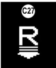
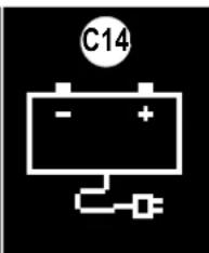

natural_image
Simple graphic of three upward-pointing triangles with a small circle in the corner (no text or symbols)
natural_image
Pixelated white padlock icon on black background, no text or symbols present
natural_image
Pure electrical circuit symbol for a battery, no text or labels present
natural_image
Simple icon of a laboratory flask with a circular head, no text or symbols present
natural_image
Simple icon of a sun with a horizontal line beneath it, no text or symbols present.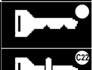
natural_image
Two abstract white icons on black background: one resembling a key with a circle, the other resembling a tool or device (no text or symbols)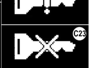
natural_image
Pure electrical circuit lines without any symbolsUSO DEL SISTEMA DE DETERGENTE (ECOFLEX)
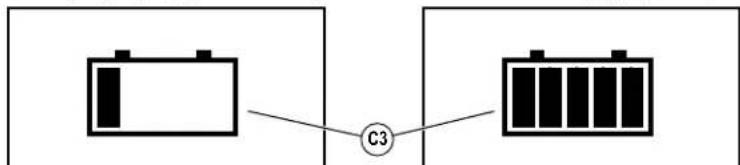
flowchart
graph LR
    A[" "] --> C[" "]
    C --> D[" "]
    style A fill:#fff,stroke:#000
    style D fill:#fff,stroke:#000
    classDef box1 stroke:#000,stroke-width:2px;
    classDef box2 stroke:#000,stroke-width:2px;
    classDef box3 stroke:#000,stroke-width:2px;
    class A,B,C box1;
CARGA DE LAS BATERÍAS DE GEL/AGM (VRLA)
flowchart
graph LR
    A[" "] --> C[" "]
    C --> D[" "]
    style A fill:#fff,stroke:#000
    style D fill:#fff,stroke:#000
    classDef box1 stroke:#000,stroke-width:2px;
    classDef box2 stroke:#000,stroke-width:2px;
    classDef box3 stroke:#000,stroke-width:2px;
    class A,B,C box1;
MANTENIMIENTO DE LA HOJA LATERAL
FIGURA 4-7
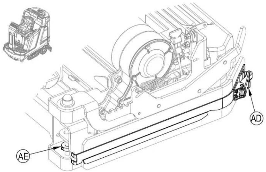
Accessoires/Options....40
APPRENEZ À CONNAÎTRE VOTRE MACHINE
PANNEAU DE COMMANDE
PANNEAU DE COMMANDE - SUITE
natural_image
Simple white checkmark inside a square frame with number 20 above (no text or symbols on the diagram itself)

natural_image
Simple graphic of three upward-pointing triangles with a small circle in the corner (no text or symbols)
natural_image
Pixelated white padlock icon on black background, no text or symbols present
natural_image
Pure electrical circuit symbol for a battery, no text or labels present
natural_image
Simple icon of a laboratory flask with a circular head, no text or symbols present
natural_image
Simple icon of a sun with a horizontal line beneath it, no text or symbols present.
natural_image
Two abstract white shapes on black background: one resembling a key with a circle, the other resembling a tool or device (no text or symbols)
natural_image
Pure electrical circuit lines without any symbolsAFFICHAGE DU MENU D'INFORMATION
Affichage du menu
PRÉPARATION DE LA MACHINE
BATTERIES
REMLISSAGE DU RÉSERVOIR DE SOLUTION
INDICATEUR DU RÉSERVOIR DE SOLUTION
PRÉPARATION DU SYSTÈME DE DÉTERGENT (MODÈLES ECOFLEX UNIQUEMENT) REMLISSEZ LA CARTOUCHE DE DÉTERGENT
ATTENTION!
FREIN ÉLECTROMAGNÉTIQUE
ATTENTION!
CHARGEMENT DES BATTERIES SÈCHES/AGM (VRLA)
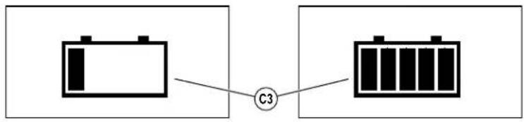
flowchart
graph LR
    A[" batteries "] --> C[" C3 "]
    C --> D[" batteries "]
    style A fill:#f9f,stroke:#333
    style D fill:#bbf,stroke:#333
ENTRETIEN DE LA LAME LATÉRALE
FIGURE 4-7
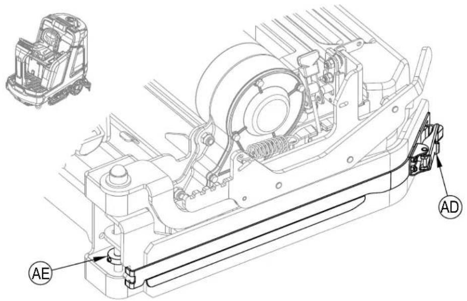
RÉGLAGE DE LA PRESSION DES LAMES LATÉRALES - CYLINDRIQUES UNIQUEMENT
LAME LATÉRALE - POSITION DE LAVAGE DOUBLE
DISQUE -
Erreurs actives [Active Faults]
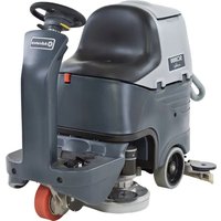
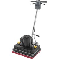
- Instructions for Use
- WARNING:
- TABLE OF CONTENTS
- INTRODUCTION
- CAUTION!
- PARTS AND SERVICE
- MODIFICATIONS
- NAME PLATE
- UNCRATE THE MACHINE
- TRANSPORTING THE MACHINE
- CAUTIONS AND WARNINGS
- SYMBOLS
- DANGER!
- WARNING!
- GENERAL SAFETY INSTRUCTIONS
- CAUTIONS AND WARNINGS - CONTINUED
- SAVE THESE INSTRUCTIONS
- REGULATORY
- FCC:
- IC:
- KNOW YOUR MACHINE
- CONTROL PANEL
- CONTROL PANEL - CONTINUED
- INFORMATION MENU DISPLAY
- Menu Display
- INFORMATION MENU DISPLAY - CONTINUED
- MAGNETIC SMARTKEY
- PREPARE THE MACHINE FOR USE
- BATTERIES
- INSTALL THE BATTERIES
- When Servicing Batteries...
- BATTERIES - CONTINUED
- INSTALL THE BRUSHES (DISC SYSTEM)
- INSTALL THE BRUSHES (CYLINDRICAL SYSTEM)
- FILLING THE SOLUTION TANK
- SOLUTION TANK INDICATOR
- SQUEEGEE INSTALLATION
- DETERGENT SYSTEM PREPARATION (ECOFLEX MODELS ONLY)
- FILL THE DETERGENT CARTRIDGE
- DETERGENT SYSTEM PURGE (ECOFLEX MODELS ONLY)
- To Purge When Changing Detergent (SCRUB AND SOLUTION SYSTEMS MUST BE OFF):
- To Purge Weekly (SCRUB AND SOLUTION SYSTEMS MUST BE OFF):
- DETERGENT SYSTEM USE (ECOFLEX)
- Detergent Use (SCRUB AND SOLUTION SYSTEM MUST BE ON): See Figure 2-9.
- To program the Detergent High Level
- To program the Detergent Low Level
- DETERGENT SYSTEM PREPARATION AND USE (ECOFLEX)
- STARTING THE MACHINE
- STOPPING THE MACHINE
- OPERATING THE MACHINE - CONTINUED
- To Scrub...
- WET VACUUMING
- AFTER USE
- MAINTENANCE
- MAINTENANCE SCHEDULE
- CLEANING RECOVERY TANK
- CLEANING SOLUTION FILTER
- LUBRICATING THE MACHINE
- ELECTROMAGNETIC BRAKE
- CHARGING WET BATTERIES
- CHECKING THE BATTERY WATER LEVEL
- CHARGING GEL/AGM (VRLA) BATTERIES
- To Reverse or Replace the Rear Squeegee Wiping Blade...
- To Reverse or Replace the Front Squeegee Blade...
- SQUEEGEE ADJUSTMENT
- SQUEEGEE MAINTENANCE - CONTINUED
- DISC - To reverse or replace the scrub system side blades ...
- CYLINDRICAL - To reverse or replace the scrub system side blades ...
- SIDE BLADE HEIGHT ADJUSTMENT
- DISC -
- CYLINDRICAL -
- SIDE BLADE PRESSURE ADJUSTMENT - CYLINDRICAL ONLY
- TROUBLESHOOTING
- GENERAL MACHINE TROUBLESHOOTING
- FAULT CODE DISPLAY
- FAULT CODE HISTORY
- SPECIFICATIONS
- ACCESSORIES / OPTIONS
- TECHNICAL SPECIFICATIONS
- (AS INSTALLED AND TESTED ON THE UNIT)
- ÍNDICE
- CONOZCA SU MÁQUINA
- PANEL DE CONTROL
- USO DEL SISTEMA DE DETERGENTE (ECOFLEX)
- CARGA DE LAS BATERÍAS DE GEL/AGM (VRLA)
- MANTENIMIENTO DE LA HOJA LATERAL
- APPRENEZ À CONNAÎTRE VOTRE MACHINE
- PANNEAU DE COMMANDE
- PANNEAU DE COMMANDE - SUITE
- AFFICHAGE DU MENU D'INFORMATION
- Affichage du menu
- PRÉPARATION DE LA MACHINE
- REMLISSAGE DU RÉSERVOIR DE SOLUTION
- INDICATEUR DU RÉSERVOIR DE SOLUTION
- PRÉPARATION DU SYSTÈME DE DÉTERGENT (MODÈLES ECOFLEX UNIQUEMENT) REMLISSEZ LA CARTOUCHE DE DÉTERGENT
- ATTENTION!
- FREIN ÉLECTROMAGNÉTIQUE
- CHARGEMENT DES BATTERIES SÈCHES/AGM (VRLA)
- ENTRETIEN DE LA LAME LATÉRALE
- RÉGLAGE DE LA PRESSION DES LAMES LATÉRALES - CYLINDRIQUES UNIQUEMENT
- LAME LATÉRALE - POSITION DE LAVAGE DOUBLE
- DISQUE -
Brand : ADVANCE
Model : SC5000 34D
Category : Floor cleaner