SCLX3015BKNBB - Basket FABER - Free user manual and instructions
Find the device manual for free SCLX3015BKNBB FABER in PDF.

| Product Type | Built-in hood (downdraft) |
| Brand | Faber |
| Model | SCLX3015BKNBB |
| Width | 30" (76 cm) |
| Depth | 16" (40.6 cm) |
| Height (adjustable) | 25 1/4" - 31 1/4" (64 - 79 cm) |
| Duct Diameter | 6" (15.2 cm) for exhaust, 10" (25.4 cm) for remote ventilator |
| Number of Speeds | 4 + intensive (6 min timed) |
| Lighting | LED, dimmable |
| Controls | Touch LED controls |
| Delay Function | Yes, automatic delayed shut-off after 30 minutes |
| Grease Filter Alarm | Yes, after 100 hours of operation |
| Carbon Filter Alarm | Yes, after 200 hours of operation |
| Remote Control | Optional (sold separately) |
| Filter Type | Washable metal grease filters (dishwasher safe) |
| Activated Carbon Filter | Optional (for recirculation) |
| Material | Stainless steel and glass |
| Warranty | 1 year parts and labor |
Frequently Asked Questions - SCLX3015BKNBB FABER
User questions about SCLX3015BKNBB FABER
0 question about this device. Answer the ones you know or ask your own.
Ask a new question about this device
Download the instructions for your Basket in PDF format for free! Find your manual SCLX3015BKNBB - FABER and take your electronic device back in hand. On this page are published all the documents necessary for the use of your device. SCLX3015BKNBB by FABER.
USER MANUAL SCLX3015BKNBB FABER
natural_image
Technical line drawing of a mechanical or architectural component with a rectangular frame and circular cutout (no text or symbols)SCIROCCO LUX
Installation Instructions
Use and Care Information
READ AND SAVE THESE INSTRUCTIONS BEFORE YOU START INSTALLING THIS RANGEHOOD
WARNING: - TO REDUCE THE RISK OF A RANGE TOP GREASE FIRE:
a) Never leave surface units unattended at high settings. Boilovers cause smoking and greasy spillovers that may ignite. Heat oils slowly on low or medium setting.
b) Always turn hood ON when cooking at high heat or when flambeing food (i.e. Crepes Suzette, Cherries Jubilee, Peppercorn Beef Flambé).
c) Clean ventilating fans frequently. Grease should not be allowed to accumulate on fan or filter.
d) Use proper pan size. Always use cookware appropriate for the size of the surface element.
WARNING: - TO REDUCE THE RISK OF INJURY TO PERSONS IN THE EVENT OF A RANGE TOP GREASE FIRE, OBSERVE THE FOLLOWING*:
a) SMOTHER FLAMES with a close-fitting lid, cookie sheet, or metal tray, then turn off the burner. BE CAREFUL TO PREVENT BURNS. If the flames do not go out immediately EVACUATE AND CALL THE FIRE DEPARTMENT.
b) NEVER PICK UP A FLAMING PAN - You may be burned.
c) DO NOT USE WATER, including wet dishcloths or towels - a violent steam explosion will result.
d) Use an extinguisher ONLY if:
1. You know you have a Class ABC extinguisher, and you already know how to operate it.
2. The fire is small and contained in the area where it started.
3. The fire department is being called.
4. You can fight the fire with your back to an exit.
* Based on "Kitchen Firesafety Tips" published by NFPA
WARNING - TO REDUCE THE RISK OF FIRE OR ELECTRIC SHOCK, do not use this fan with any solid-state speed control device.
WARNING - TO REDUCE THE RISK OF FIRE, ELECTRICAL SHOCK, OR INJURY TO PERSONS, OBSERVE THE FOLLOWING:
- Use this unit only in the manner intended by the manufacturer. If you have any questions, contact the manufacturer.
- Before servicing or cleaning unit, switch power off at service panel and lock the service disconnecting means to prevent power from being switched on accidentally. When the service disconnecting means cannot be locked, securely fasten a prominent warning device, such as a tag, to the service panel.
CAUTION: For General Ventilating Use Only. Do Not Use To Exhaust Hazardous or Explosive Materials and Vapors.
WARNING - TO REDUCE THE RISK OF FIRE, ELECTRICAL SHOCK, OR INJURY TO PERSONS, OBSERVE THE FOLLOWING:
- Installation Work And Electrical Wiring Must Be Done By Qualified Person(s) In Accordance With All Applicable Codes And Standards, Including Fire-Rated Construction.
-
Sufficient air is needed for proper combustion and exhausting of gases through the flue (chimney) of fuel burning equipment to prevent backdrafting. Follow the heating equipment manufacturer's guideline and safety standards such as those published by the National Fire Protection Association (NFPA), and the American Society for Heating, Refrigeration and Air Conditioning Engineers (ASHRAE), and the local code authorities.
-
When cutting or drilling into wall or ceiling, do not damage electrical wiring and other hidden utilities.
- Ducted fans must always be vented to the outdoors.
ALL WALL AND FLOOR OPENINGS WHERE THE RANGEHOOD IS INSTALLED MUST BE SEALED.
This rangehood requires at least 24" of clearance between the bottom of the rangehood and the cooking surface or countertop. This hood has been approved by UL at this distance from the cooktop.
This minimum clearance may be higher depending on local building codes. For gas cooktops and combination ranges, a minimum of 30" is recommended and may be required. The maximum depth of overhead cabinets is 13". Overhead cabinets on both sides of this unit must be a minimum of 18" above the cooking surface or countertop. Consult the cooktop or range installation instructions given by the manufacturer before making any cutouts. MOBILE HOME INSTALLATION The installation of this rangehood must conform to the Manufactured Home Construction and Safety Standards, Title 24 CFR, Part 3280 (formerly Federal Standard for Mobile Home Construction and Safety, Title 24, HUD, Part 280). See Electrical Requirements.
VENTING REQUIREMENTS
Determine which venting method is best for your application. Ductwork can extend either through the wall or the floor.
The length of the ductwork and the number of elbows should be kept to a minimum to provide efficient performance. The size of the ductwork should be uniform. Do not install two elbows together. Use duct tape to seal all joints in the ductwork system. Use caulking to seal exterior wall or floor opening around the cap.
Flexible ductwork is not recommended. Flexible ductwork creates back pressure and air turbulence that greatly reduces performance.
Make sure there is proper clearance within the wall or floor for exhaust duct before making cutouts. Do not cut a joist or stud unless absolutely necessary. If a joist or stud must be cut, then a supporting frame must be constructed.
WARNING - To Reduce The Risk Of Fire, Use Only Metal Ductwork.
CAUTION - To reduce risk of fire and to properly exhaust air, be sure to duct air outside – Do not vent exhaust air into spaces within walls or ceilings or into attics, crawl spaces, or garages.
Cold Weather installations
An additional back draft damper should be installed to minimize backward cold air flow and a nonmetallic thermal break should be installed to minimize conduction of outside temperatures as part of the vent system. The damper should be on the cold air side of the thermal break. The break should be as close as possible to where the vent system enters the heated portion of the house.

WARNING
- Venting system MUST terminate outside the home.
- DO NOT terminate the ductwork in an attic or other enclosed space.
- DO NOT use 4" laundry-type wall caps.
- Flexible-type ductwork is not recommended.
- DO NOT obstruct the flow of combustion and ventilation air.
- Failure to follow venting requirements may result in a fire.

WARNING
• Electrical ground is required on this rangehood.
- If cold water pipe is interrupted by plastic, nonmetallic gaskets or other materials, DO NOT use for grounding.
- DO NOT ground to a gas pipe.
- DO NOT have a fuse in the neutral or grounding circuit. A fuse in the neutral or grounding circuit could result in electrical shock.
- Check with a qualified electrician if you are in doubt as to whether the rangehood is properly grounded.
- Failure to follow electrical requirements may result in a fire.
State of California Proposition 65 Warning (US only)
WARNING
This product contains chemicals known to the State of California to cause cancer and birth defects or other reproductive harm.
For more information go to www.P65Warnings.ca.gov
RANGEHOOD DIMENSIONS
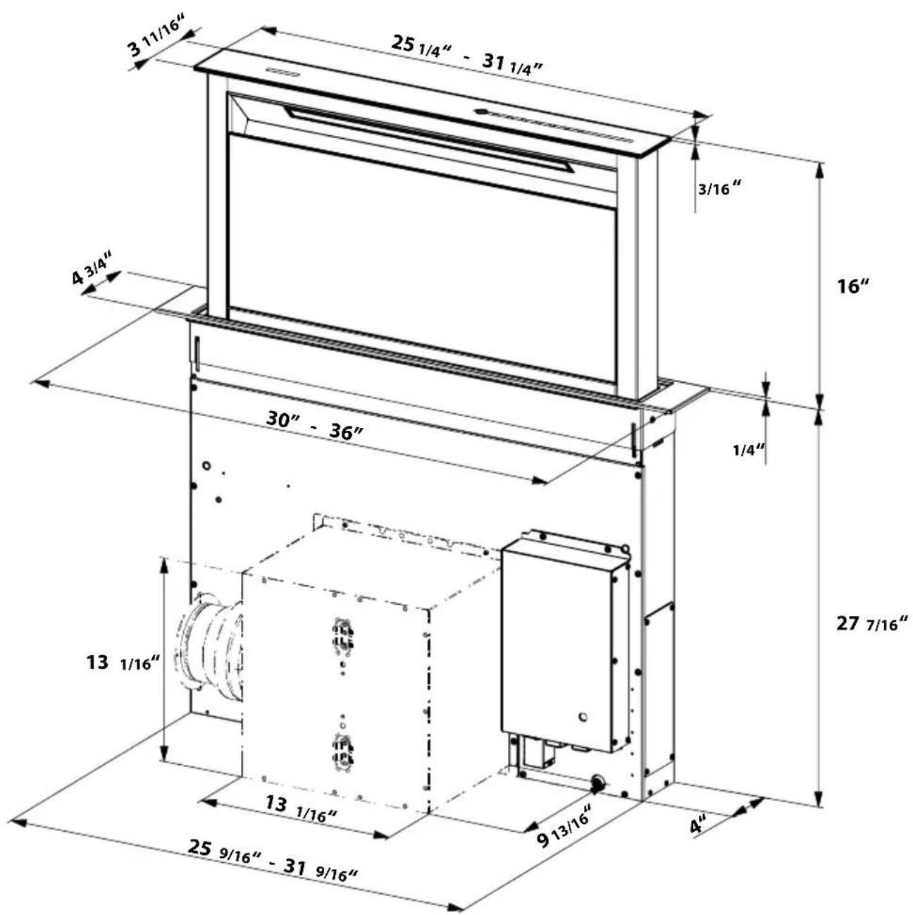
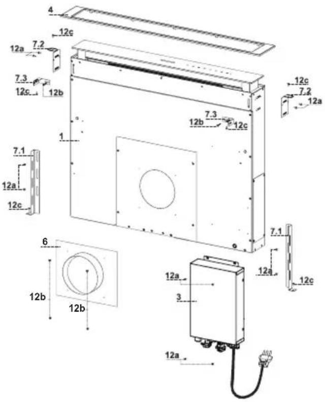
MAIN PARTS
Components
Ref. Qty. Product Components
1 1 Hood Canopy complete with:
Controls, Light, Filters.
3 1 Electric unit.
4 1 Top Frame
6 1 Duct Collar 10" duct collar used with Remote Blowers
Ref. Qty. Installation Components
7.1 2 Lower Fixing Bracket
7.2 2 Top Side Fixing Bracket
7.3 2 Top Front Bracket
12a 16 Screws 1/8" x 3/8"
12b 6 Screws 3/16" x 5/16"
12c 8 Screws 3/16" x 9/16"
Qty. Documentation
1 Instruction Manual
10" duct collar used with Remote Blowers
Parts needed
- 6" Round Metal ductwork.
Available Accessories (Purchased separately)
Recirculation Kit - sku # DUCTSCIR
Recirculation Vent Kit - Activated Charcoal Filter - FILTERSCIR
Internal Blower model - IBDD600-B
Remote Blower model - RB900, RB1200 (WIREBOX for Remote Blower included)
Wireless Remote Control - REMCTRL
Wiring box for Remote Blower - WIREBOXSCLX
Installation Instructions
1
FOR YOUR SAFETY:
WARNING Before beginning the installation, switch power off at service panel and lock the service disconnecting means to prevent power from being switched on accidentally. When the service disconnecting means cannot be locked, securely fasten a prominent warning device, such as a tag, to the service panel.
| Hood X Y | ||
| 30" 25 | 15/16" 4 5/16" | |
| 36" 31 | 15/16" 4 5/16" | |
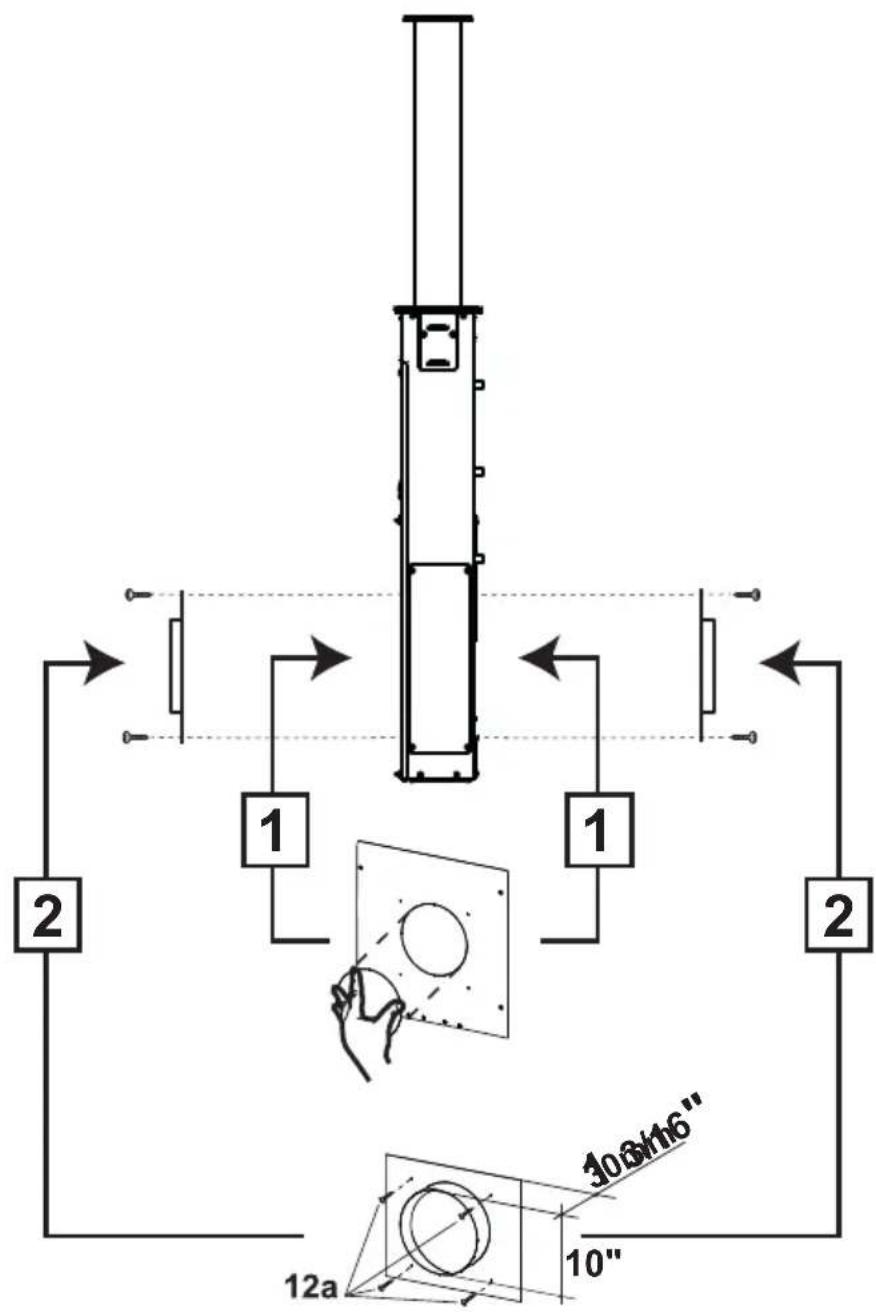
Cutout Dimensions
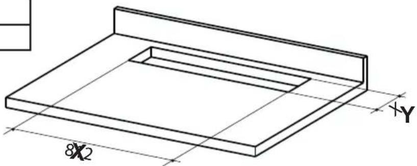
natural_image
Technical line drawing of a rectangular frame with dimension annotations (8x2 and x-y axes) — no readable text or symbols beyond measurement markers.The minimum distance between the opening for the cooktop and the one for the hood must be of at least 1 3/16" - 1 15/16" according to the strength of the material used for the working top.
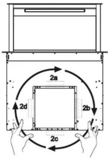
2
Inserting the Hood Canopy into the countertop from below
- Insert the Hood Canopy from below into the countertop cutout, drilled as described above.
- With the aid of a support, lift the Hood Canopy until the front comes out of the countertop.
- Insert the Brackets 7.2, as indicated in the figure, into the slots provided and fix them with the screws 12a provided.
• Center the Hood Canopy with respect to the Cooktop slot.
• Using the 2 screws 12c provided, secure the Hood Canopy to the countertop and remove the supports.
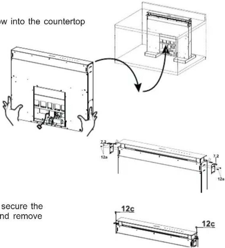
Warning:
If the countertop is made from a material that does not allow the screws 12c to be inserted, use a small amount of silicone to glue the Brackets 7.2 to the top and allow it to dry completely before proceeding with installation.
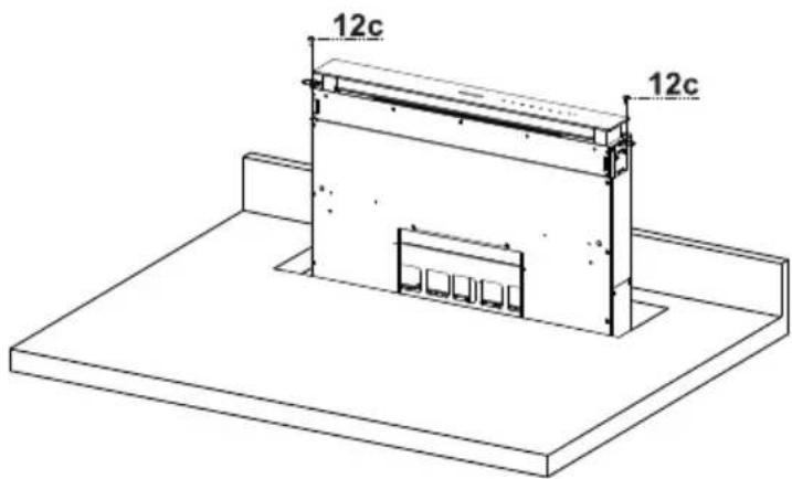
3
Inserting the Hood Canopy into the countertop from above
- Insert the Brackets 7.2, as indicated in the figure, into the slots provided and fix them with the screws 12a provided.
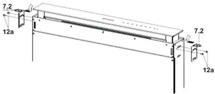
- Insert the Hood Canopy into the countertop, drilled as described above. - Center the Hood Canopy with respect to the cooktop slot. - Secure the Hood Canopy with the 2 screws 12c provided.
Warning:
If the countertop is made from a material that does not allow the screws 12c to be inserted, use a small amount of silicone to glue the Brackets 7.2 to the top and allow it to dry completely before proceeding with installation.
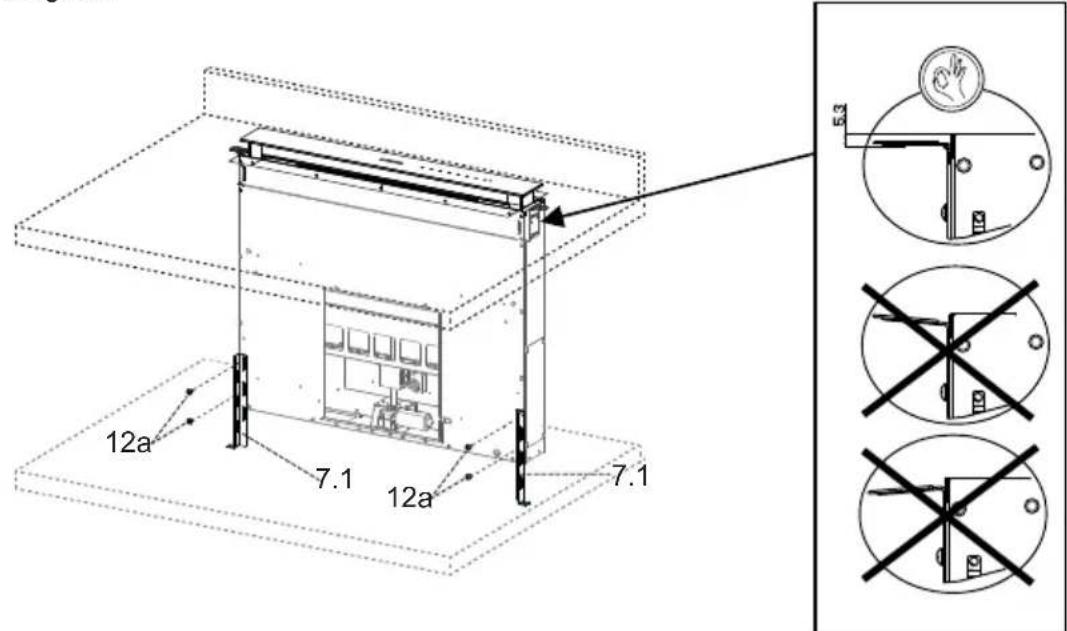
4
Securing the Lower Brackets
- Screw the brackets 7.1 to the front of the Hood Canopy using the screws 12a provided. - Before tightening the Brackets completely, make all the adjustments to allow them to rest on the lower base of the Cabinet Base to avoid deformation of the upper brackets 7.2 as shown in the figure.
5
Leveling and Securing the Lower Brackets
- With the aid of a level, set the Hood Canopy level vertically and secure it to the Lower Surface using 2 screws 12c provided.
- Tighten the screws 12a completely.
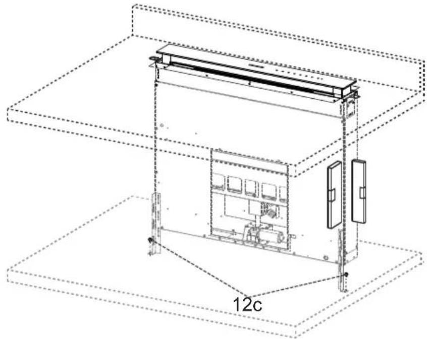
6
Securing the Squaring Brackets
- Screw the brackets 7.3 to the Hood Canopy using the screws 12b provided, without tightening completely.
- Using the screws 12c provided, fasten the other part of the brackets 7.3 either to the side walls of the unit or to the lower part of the cooktop.
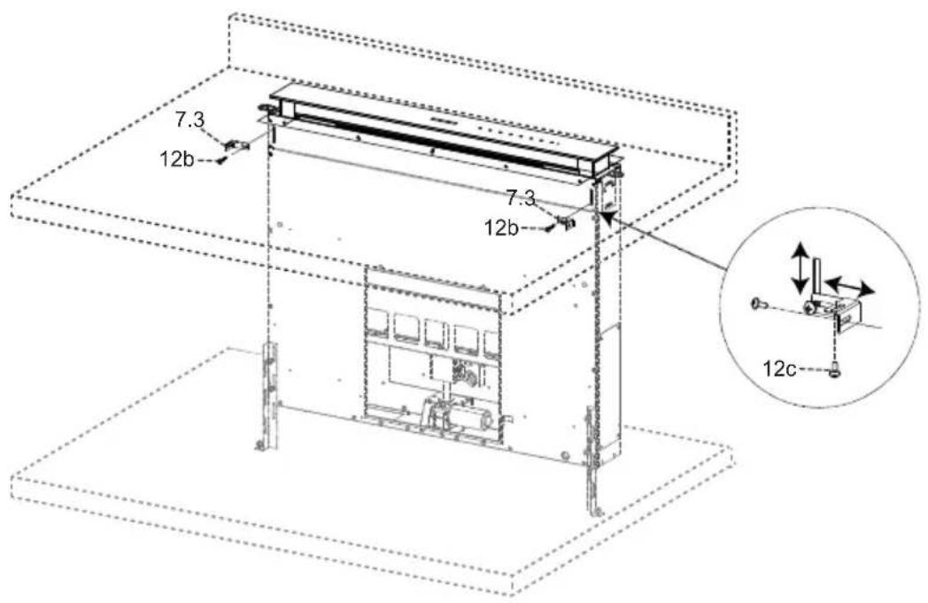
- Tighten the screws 12c and 12b completely.
7a
Internal Blower Installation
CAUTION - To Reduce The Risk Of Fire And Electric Shock, Install This Down Draft Only With Integral Blowers IBDD600-B Manufactured by Faber.
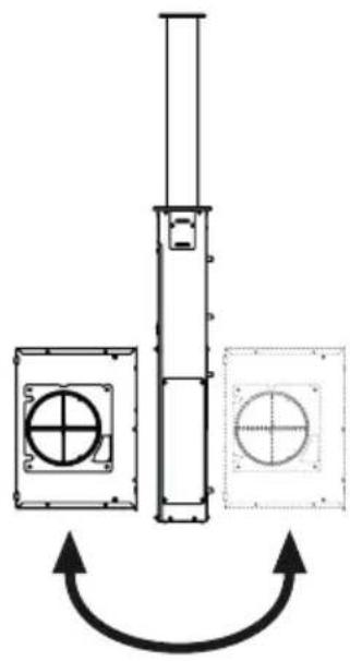
1
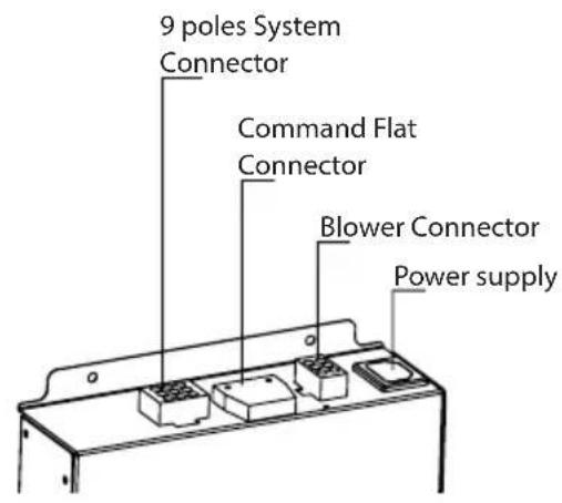
• Installation of the Internal Blower (1) at the front or rear must be decided according to the position of the cooktop, making sure that the plug is properly positioned.
natural_image
Pure mechanical diagram showing a vertical shaft and two circular components with crosshair indicators, no text or symbols present.2
- The Internal Blower can be rotated as shown in the figure 2 for multiple venting directions..
- Screw the Internal Blower to the Hood Canopy using the screws 12a and 12b provided as shown in the figure.
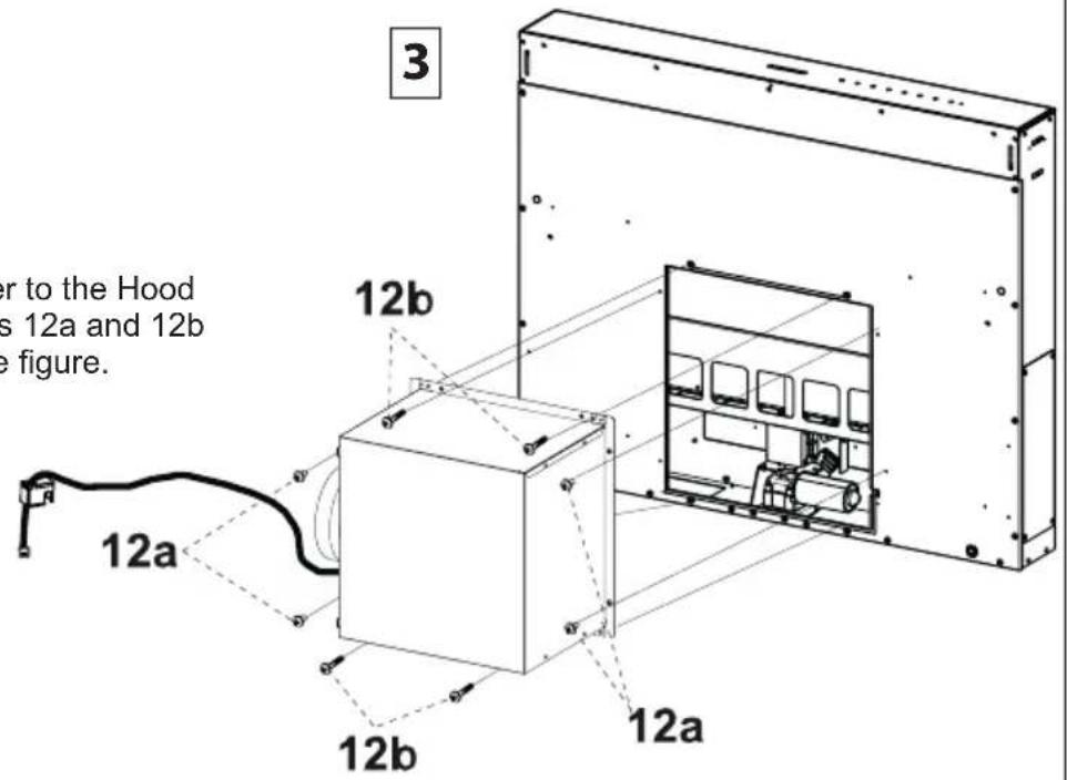
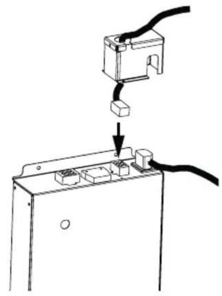
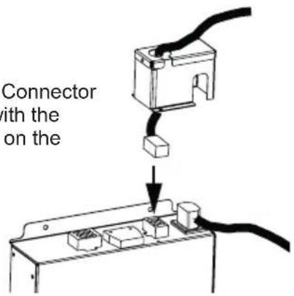
- Connect the Wire Connector from the Blower with the correct connector on the Electric Unit.
natural_image
Diagram showing a cable being inserted into an electrical enclosure, with no text or symbols present.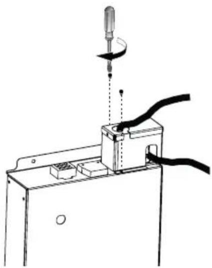
natural_image
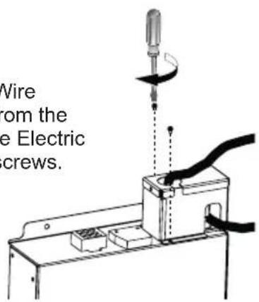
Technical line drawing of a mechanical assembly with a tool and cable (no text or symbols)- Secure the Wire Connector from the Blower at the Electric Unit with 2 screws.
7b
Installation of Remote Blower
CAUTION - To Reduce The Risk Of Fire And Electric Shock, Install This Down Draft Only With Remote Blowers RB900, RB1200 Manufactured by Faber.
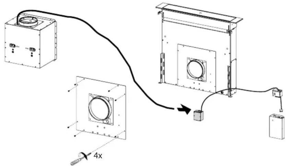
Connect the Remote Blower wiring to the connector of the Electric Unit. Accessories needed:
- Remote Blower model - RB900, RB1200 (purchased separately).
- WIREBOXSCLX for Remote Blower (purchased separately).
Attention: Install the Wiring Box with two screws (provided) on a flat and dry surface.
Connect the Remote Blower wiring plug connector to the connector of the Electric Unit.
Run 2-wire plus ground power cable from the Remote Blower to wiring box on the Cover according to local codes and ordinances. Use Listed fittings.
- Connect the Wire Connector from the Blower with the correct connector on the Electric Unit.
- Secure the Wire Connector from the Blower at the Electric Unit with 2 screws.
Installation of wiring connection
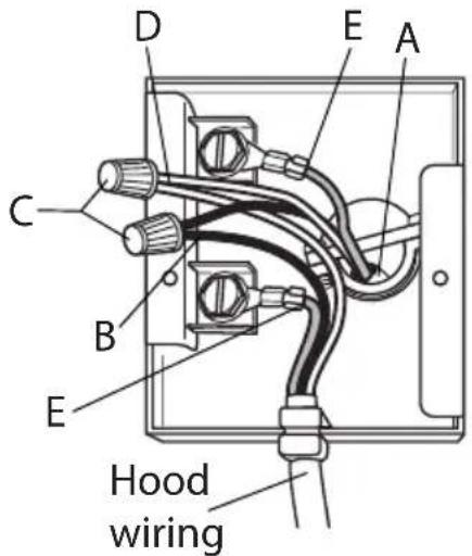
Remove the wiring electrical knockout using a flat-blade screwdriver. Feed the Power Supply Cable through the electrical knockout.
Connect the Power Supply Cable to the Remote Blower. Attach the White lead of the power supply (A) to the White lead of the rangehood (D) with a twist-on type wire connector. Attach the Black lead of the power supply to the Black lead of the rangehood (B) with a twist-on type wire connector (C). Connect the Green (E) (Green and Yellow) ground wire under the Green grounding screws. Replace the field wiring compartment cover
Connect the ductwork to the damper and seal all connections with duct tape.
Turn the power supply on. Turn on the blower and light. If the rangehood does not operate, check that the circuit breaker is not tripped or the house fuse blown. If the unit still does not operate, disconnect the power supply and check that the wiring connections have been made properly.
8
Installation of Electrical Module
- Connect the wires coming out of the bottom right part of the Hood Canopy to the corresponding connector on the Electric Unit, taking care not to make any wrong connections. Check the picture below.

natural_image
Technical line drawing of a mechanical assembly with no visible text or symbols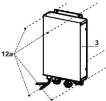
- Secure the Electric Unit to the Hood Canopy using the screws 12a provided.
- The Electric Unit can be installed on the left or right of the front of the hood canopy as shown above. It can also be installed on the cabinet base if space allows.
Connect the ductwork to the damper and seal all connections with duct tape.
Turn the power supply on. Turn on the blower and light. If the rangehood does not operate, check that the circuit breaker is not tripped or the house fuse blown. If the unit still does not operate, disconnect the power supply and check that the wiring connections have been made properly.
"GROUNDING INSTRUCTIONS"
This appliance must be grounded. In the event of an electrical short circuit, grounding reduces the risk of electric shock by providing an escape wire for the electric current. This appliance is equipped with a cord having a grounding wire with a grounding plug. The plug must be plugged into an outlet that is properly installed and grounded.
WARNING - Improper grounding can result in a risk of electric shock.
Consult a qualified electrician if the grounding instructions are not completely understood, or if doubt exists as to whether the appliance is properly grounded.
Do not use an extension cord. If the power supply cord is too short, have a qualified electrician install an outlet near the appliance."
Warning.: Do not install the product in such a way that the electric unit is in contact with the floor.
Connection the Air outlet with the Accessories Remote Motor
To connect the Hood to the outlet pipe, select the version that applies.
Standard Outlets
According to your venting direction (Front or Rear), break off the outlet hole already marked and screw on callout number from Main Parts Component using the 4 screws 12a provided.
9
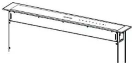
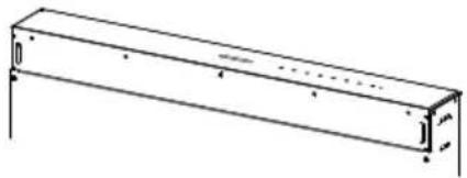
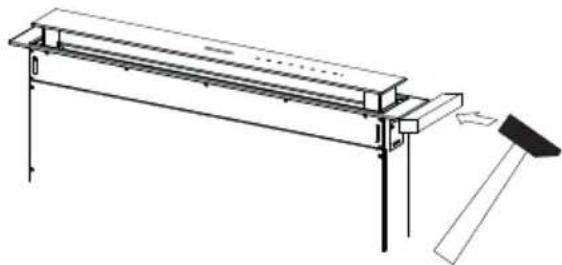
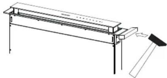
Installation of Top Frame
- Raise the downdraft to the Upper Position by a 1-2" (See Page 15 for Use of Controls).
- Remove the sponge guards from the corners of the glass.
• Take the Top Frame and insert it from above, making sure that its tabs insert into the slots provided on the downdraft and sliding it to the left.
Warning...: All the tabs must be inserted.
- Use a soft rubber mallet or similar tool to tap all along the Top Frame from right to left until it is completely flush.
A piece of wood or rubber block can be inserted between the hammer and the front Frame to prevent any damage.
- Please refer to the paragraph on Use for indications of how to return the downdraft to the Standard position.
natural_image
Pure technical line drawing of a rectangular beam or support structure without any text, numbers, or symbols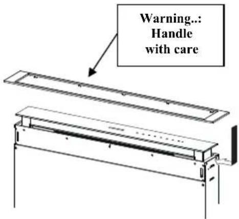
natural_image
Technical line drawing of a mechanical assembly with supports and a tool (no text or symbols)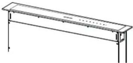
natural_image
Simple line drawing of a rectangular table with vertical supports and a horizontal bar (no text or symbols)10
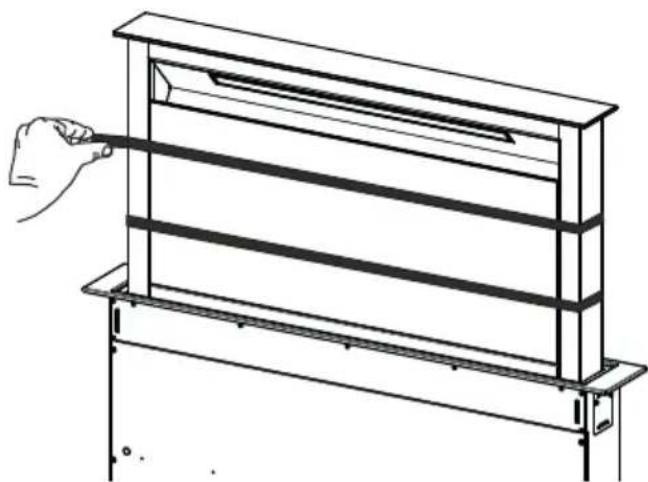
Front Cover Panel
- Raise the telescopic part to the Upper Position (See Page 15 for Use of Controls).
- Remove the 2 strips of adhesive tape fastening the panel during transport.
natural_image
Line drawing of a hand holding a rectangular frame with horizontal bars, no text or symbols presentUSE AND CARE INFORMATION
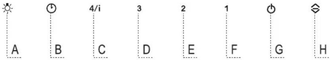
| Button | Functio n LED b u | t t on |
| A | The button only works when the downdraft is open. | |
| Press Briefly = Turns the Lights On/Off at maximum intensity. | ||
| Press and hold for 2 Seconds = Turns the Dimmer Lights On/Off. | ||
| B | Only works with the downdraft Open.Press briefly = Activates/Deactivates Delay mode, causing automatic shutdown of the Motor and the Lighting system from any speed with a 15' delay. It is disabled by pressing the same button again, turning the motor off or closing the downdraft. | LED Button B+ Button for the set Speed are lit. |
| Works both with the downdraft Up and Down.Press and hold for 2 Seconds = With the filter alarm triggered the Filter Alarm is Reset. These indications are only visible when the motor is turned off. | LED button ON:Indicates the need to wash the metal grease filters.The alarm is triggered after the Hood has been in operation for 100 working hours.Flashing LED button:Indicates the need to change the activated charcoal filters, and also to wash the metal grease filters. The alarm is triggered after the Hood has been in operation for 200 working hours. | |
| Works both with downdraft Up and Down with Motor + Lights = Off.Press and hold for 4 Seconds = Enables/disables the Keyboard lock. | All the LED buttons flash twice. During the Lock the LED buttons light up in sequence. | |
| C | Only works with the downdraft Up.Press briefly = Activates speed four. | LED button ON. |
| Only works with the downdraft Up.Press and hold for 2 seconds = Enables/Disables the Intensive speed. This speed is timed to run for 6 minutes. At the end of this time the system will return to the speed set previously.It is disabled by pressing the same button again, turning the motor off or closing the downdraft. | Flashing LED button. | |
| D | Only works with the downdraft Up.Activates speed three. | LED button ON. |
| E | Only works with the downdraft UpActivates/Deactivates speed two. | LED button ON. |
| F | Only works with the downdraft Up.Press briefly = Activates/Deactivates speed one. | LED button NO. |
| downdraft Up and DownPress and hold for 2 Seconds = Enables/Disables the Activated Charcoal Filter Alarm with the Motor turned off and no Filter Alarm triggered. | LED button B flashes twice = Activated Charcoal filter Alarm Activated.LED button B flashes once = Activated Charcoal filter Alarm Deactivated. | |
| G downdraft UpPress briefly = Turns the Motor off. | LED button goes out. | |
| LED button G + F flashes twice = Remote control Enabled.LED button G + F flashes once = Remote control Disabled. | ||
| H | downdraft Up = Lower the downdraft + Lights and Motor Off downdraft Down = Upper the downdraft + Lights and Motor On.Warning: If the downdraft remains partially open for any reason, press the Button to complete the opening or closing cycle. | |
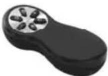
Remote Control (Purchased Separately)
The appliance can be controlled using a remote control powered by a 1.5 V carbon-zinc alkaline batteries of the standard LR03-AAA type (not included).
- Do not place the remote control near to heat sources.
• Used batteries must be disposed of in the proper manner.

natural_image
Illustration of a car interior with a circular vent and a green arrow indicating direction (no text or symbols)Remote Control Panel
Warning.: The remote control receiver is deactivated when first supplied. To activate it, see the paragraph Use Function of Button G.
| Motor | downdraft Down:Opens the downdraft, turns the motor on at speed one and turns the lights on at maximum intensity. | |
| downdraft Up:Brief pressure: Motor On / Off.Pressed for 2 Seconds: Closes the downdraft and Motor + Lights = Off. | ||
| - | Only with downdraftUpDecreases the working speed each time it is pressed. | |
| + | Only with downdraft UpIncreases the working speed each time it is pressed. | |
| i | Intensive | Only with downdraft UpActivates the Intensive function. |
| j | Delay | Only with downdraft UpActivates the Delay function. |
| Light | Only with downdraft UpBrief pressure: Lights On / Off.Pressed for 2 Seconds: Dimmer lights On / Off. |
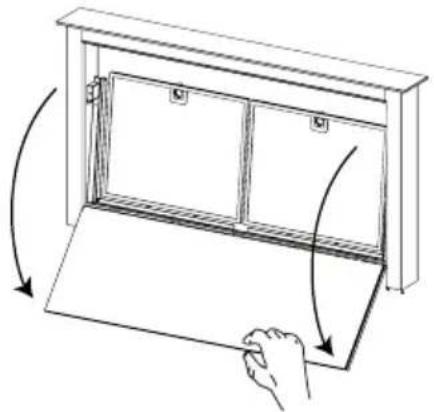
Cleaning the Front Cover Panels
- Open the Front Cover Panel by pulling it at the top.
- Disconnect the panel from the hood canopy.
- The panel must never be washed in the dishwasher.
- Clean the outside with a damp cloth and neutral detergent.
- Clean the inside using a damp cloth and neutral detergent; do not use wet cloths or sponges, or jets of water; do not use abrasive substances.
- On completing the operation hook the panel and close it.
natural_image
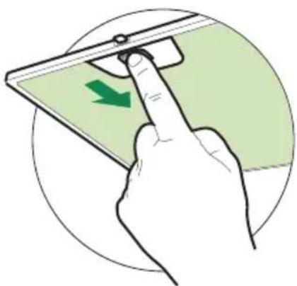
Line drawing of a cabinet with arrows indicating rotation or movement, no text or symbols presentCleaning the Metal grease filters
These can also be washed in the dishwasher, and need to be cleaned whenever button B lights up or at least once every 2 months use, or more frequently if use is particularly intensive.
Resetting the alarm signal
- Turn the Lights and the Motor off.
- Press and hold button B for 2 seconds.
Cleaning the Filters
- Raise the downdraft to the Up position (see USE).
- Pull forward on the top edge of the Front Cover to pull down.
- Remove the Filters one at a time, pushing them towards the back of the unit and at the same time pulling downward.
- Wash the Filters without bending them, and leave them to dry completely before replacing. (If the surface of the filter changes color as time goes by, this will have absolutely no effect on the efficiency of the filter itself).
- Replace, taking care to ensure that the handle faces forwards.
- Close the Front Cover panel.
natural_image
Illustration of a hand pressing a device on a green screen, with a green arrow indicating the left side (no text or symbols present)LED LIGHTING UNIT
- LED lights must be replaced by Faber factory authorized service.
Wiring Diagram
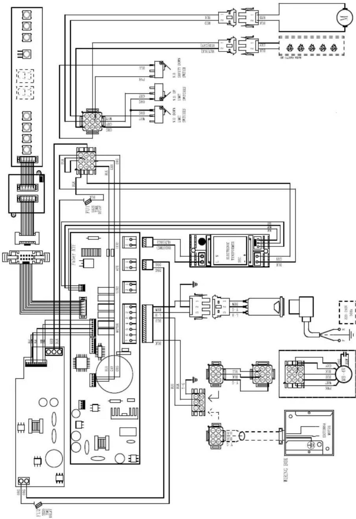
FABER
FABER CONSUMER WARRANTY & SERVICE
All Faber products are warranted against any defect in materials or workmanship for the original purchaser for a period of 1 year from the date of original purchase (requires proof of purchase). This warranty covers labor and replacement parts. Faber, at its option, may repair or replace the product or components necessary to restore the product to good working condition. To obtain warranty service, contact the dealer from whom you purchased the range hood, or the local Faber distributor. If you cannot identify a local Faber distributor, contact us at (508) 358-5353 for the name of a distributor in your area.
The following is not covered by Faber's warranty:
- Service calls to correct the installation of your range hood, to instruct you how to use your range hood, to replace or repair house fuses or to correct house wiring or plumbing.
- Service calls to repair or replace range hood light bulbs, fuses or filters. Those consumable parts are excluded from warranty coverage.
- Repairs when your range hood is used for other than normal, single-family household use.
- Damage resulting from accident, alteration, misuse, abuse, fire, flood, acts of God, improper installation, installation not in accordance with electrical or plumbing codes or Faber documentation, or use of products not approved by Faber.
- Replacement parts or repair labor costs for units operated outside the United States or Canada, including any non-UL or C-UL approved Faber range hoods.
- Repairs to the hood resulting from unauthorized modifications made to the range hood.
- Expenses for travel and transportation for product service in remote locations and pickup and delivery charges. Faber range hoods should be serviced in the home.
THIS WARRANTY DOES NOT ALLOW RECOVERY OF INCIDENTAL OR CONSEQUENTIAL DAMAGES, INCLUDING, WITHOUT LIMITATION, DIRECT, INDIRECT, INCIDENTAL, SPECIAL OR CONSEQUENTIAL DAMAGES, PERSONAL INJURY/WRONGFUL DEATH OR LOST PROFITS FABER WARRANTY IS LIMITED TO THE ABOVE CONDITIONS AND TO THE WARRANTY PERIOD SPECIFIED HEREIN AND IS EXCLUSIVE. EXCEPT AS EXPRESSLY SPECIFIED IN THIS AGREEMENT, FABER DISCLAIMS ALL EXPRESS OR IMPLIED CONDITIONS, REPRESENTATIONS, AND WARRANTIES INCLUDING, WITHOUT LIMITATION, ANY IMPLIED WARRANTIES OF MERCHANTABILITY OR FITNESS FOR A PARTICULAR PURPOSE.
This warranty gives you specific legal rights that may vary from state to state.
Model#:
Serial #: ____
January 4, 2016
VEUILLEZ LIRE ET CONSERVER LA PRÉSENTE NOTICE AVANT DE COMMENCER L'INSTALLATION DE LA HOTTE DE CUISINE
AVERTISSEMENT: POUR RÉDUIRE LE RISQUE D'UN FEU DE GRAISSE SUR LA TABLE DE CUISSON :
natural_image
Technical line drawing of a mechanical or electrical enclosure with labeled component '12c' (no text or symbols beyond label)6
natural_image
Pure mechanical diagram showing a vertical shaft and two circular components with crosshair indicators, no text or symbols present.2

natural_image
Diagram showing a cable being inserted into an electrical enclosure, with no text or symbols present.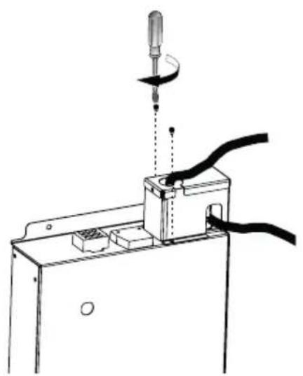
natural_image
Technical line drawing of a mechanical assembly with a tool and cable (no text or symbols)natural_image
Technical line drawing of a mechanical assembly with no visible text or symbols
natural_image
Pure technical line drawing of a rectangular beam or support structure without any text, numbers, or symbols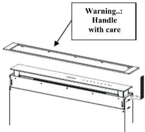
natural_image
Technical line drawing of a mechanical assembly with no visible text or symbols