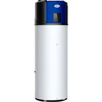
ATS-O-150VAW - Digital SLR Camera HTW - Free user manual and instructions
Find the device manual for free ATS-O-150VAW HTW in PDF.


| Product Type | Domestic Hot Water Heat Pump |
| Brand | HTW |
| Model | ATS-O-150VAW |
| Tank Capacity | 150 L |
| Power Supply | 220-240 V ~ / 50 Hz |
| Max Power Consumption | 700 W (compressor) + 1600 W (electric backup) |
| Max Current | 10 A (3.2 A + 6.8 A) |
| Max Water Temperature | 70 °C (60 °C without backup) |
| Ambient Temperature Range | -5 °C to 43 °C |
| Refrigerant Type | R134a (GWP 1430) |
| Compressor | Rotary, GMCC PJ125G1C-4DZDE |
| Max Airflow | 450 m³/h |
| Duct Diameter | 177 mm (flexible 180/200 mm) |
| Tank Material | Stainless Steel SUS304 |
| Max Working Pressure | 10 bar |
| Electric Backup Power | 1.6 kW |
| Magnesium Anode | Yes (check every 6 months) |
| Solar Heat Exchanger | Optional (SUS316, 1 m²) |
| Noise Level | 46 dB(A) |
| Dimensions (D x H) | 560 x 1490 mm |
| Net Weight | 86 kg |
| Special Functions | Timer, Wi-Fi control (optional), dehumidification, ventilation |
| Safety | High/low pressure protection, safety valve 0.7 MPa, lockout |
| Maintenance | Regular air filter cleaning, drain if not in use |
| Repairability | Service by qualified professional |
Frequently Asked Questions - ATS-O-150VAW HTW
User questions about ATS-O-150VAW HTW
0 question about this device. Answer the ones you know or ask your own.
Ask a new question about this device
Download the instructions for your Digital SLR Camera in PDF format for free! Find your manual ATS-O-150VAW - HTW and take your electronic device back in hand. On this page are published all the documents necessary for the use of your device. ATS-O-150VAW by HTW.
USER MANUAL ATS-O-150VAW HTW
OWNER'S AND INSTALLATION MANUAL
FR
MANUEL DE L'UTILISATEUR ET D'INSTALLATION
PT
natural_image
Two water heaters side by side, one with blue control panel and one with black cover (no visible text or symbols)ACUMULADOR AEROTÉRMICO | SANITARY WATER HEAT PUMP CHAUFFE-EAU THERMODYNAMIQUE| BOMBA DE CALOR ÁGUA SANITÁRIA | ACCUMULATORE AEROTERMICO
VAW
HTW-ATS-O-150VAW | HTW-ATS-O-200VAW
HTW-ATS-O-300VAW | HTW-ATS-O-500VAW
Por favor lea atentamente este manual antes de usar este producto.
Please, read carefully this manual before using the product.
natural_image
Illustration of a gasifier or cooling unit with pipes and control panel, no visible text or symbolsnatural_image
Illustration of a laundry setup with clothes hanging, air conditioner, table, and washing machine (no text or symbols)NOTA:
3.
y
Método 2:
flowchart
graph LR
    A["App icon"] -->|Search 'Smart Life-Smart Living'| B["House icon"]
    C["App icon"] -->|Search 'Smart Life-Smart Living'| D["House icon"]
Registro
Abra la aplicación.
flowchart
graph TD
    A["Working mode"] --> B["Heating"]
    B --> C["Heat+fan"]
    C --> D["Done"]
SAFETY INSTRUCTIONS....47
Warning....47
Caution....49
ITEMS INSIDE PRODUCT BOX....50
OVERVIEW OF THE UNIT....51
Parts and descriptions....51
Dimensions....52
How to replace the magnesium stick....53
Schematic overview of the water and refrigeration circuit.... 53
INSTALLATION....54
Transportation....54
Required service space....55
Installation overview. 56
Installation positions. 58
Water loop connection....59
Water affusion and water emptying. 59
Wire connection. 60
Trial running....60
User interface and operation. 61
LCD icons. 62
WIFI....66
PARAMETER CHECKING AND ADJUSTMENT 74
Parameter list....74
Malfunctioning of the unit and error codes. 75
MAINTENANCE....77
TROUBLESHOOTING....78
ENVIRONMENTAL INFORMATION....78
DISPOSAL REQUIREMENTS....79
WIRING DIAGRAM....80
TECHNICAL SPECIFICATION....82
HTW-ATS-O-***VAW 82
TEMPERATURE SENSOR R-T CONVERSION TABLE....84

READ THIS MANUAL CAREFULLY BEFORE STARTING UP THE UNIT. DO NOT THROW IT AWAY. KEEP IT IN YOUR FILES FOR FUTURE REFERENCE.

BEFORE OPERATING THE UNIT, MAKE SURE THE INSTALLATION HAS BEEN CARRIED OUT CORRECTLY BY A PROFESSIONAL DEALER. IF YOU FEEL UNSURE ABOUT
OPERATION, CONTACT YOUR DEALER FOR ADVICE AND INFORMATION.
INTRODUCTION
This manual
This manual includes the necessary information about the unit. Please read this manual carefully before you use and maintain the unit.
The unit
The hot water heat pump is one of the most economical systems to heat the water for family domestic use. Using free renewable energy from the air, the unit is highly efficient with low running costs. Its efficiency can be up to 3 \~ 4 times more than conventional gas boilers or electrical heaters.
Waste Heat recovery
Units can be installed near the kitchen, in the boiler-room or the garage, basically in every room which has a large number of waste-heat so that the unit has the higher energy efficiency even with very low outside temperatures during the winter.
Hot water and dehumidification
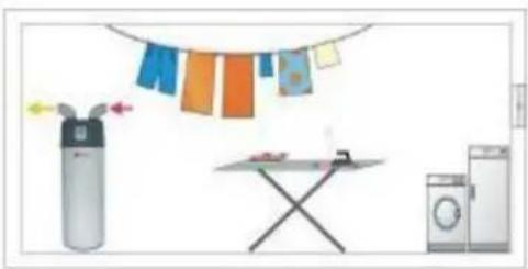
Units can be placed in the laundry room or clothing room. When it produces hot water it lowers the temperature and dehumidifies the room as well. The advantages can be experienced particularly in the humid season.
Storage room cooling
Units can be placed in the storage room as the low temperature keeps the food fresh.
Hot water and fresh air ventilation
Units can be placed in the garage, gym, basement etc. When it produces hot water, it cools the room and supplies fresh air.
Compatible with different energy sources
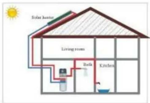
Units can be compatible with solar panels, external heat pumps, boilers or other different energy sources.
Ecological and Economical Heating
Units are the most efficient and economical alternative to both fossil fuel boilers and heating systems. By making use of the renewable source in the air, it consumes much less energy.
Compact design
Units are especially designed for offering sanitary hot water for family use. Its extremely compact structure and elegant design are suitable for indoor installation.
Multiple Functions
The special design of the air inlet and outlet makes the unit suitable for various ways of connections. With different ways of installation, the unit can work as just a heat pump but also as a fresh air blower, a dehumidifier, or an energy recovery device.
Other features
Stainless steel tank and a magnesium stick assure the durability of components and the tank.
Highly efficient compressor with the R134a refrigerant.
Electrical element available in the unit as a back-up, assuring constant hot water even in extreme cold winters.
SAFETY INSTRUCTIONS
To prevent injury to the user, other people, or property damage, the following instructions must be followed. Incorrect operation due to ignoring of instructions may cause harm or damage.
Install the unit only when it complies with local regulations, by-laws and standards. Check the main voltage and frequency. This unit is only suitable for earthed sockets, connection voltage 220 – 240 V \~ / 50Hz.
The following safety precautions should always be taken into account:
- Be sure to read the following WARNING before installing the unit.
- Be sure to observe the cautions specified here as they include important items related to safety.
- After reading these instructions, be sure to keep it in a handy place for future reference.
Warning

WARNING
Do not install the unit yourself.
Incorrect installation could cause injury due to fire, electric shock, the unit falling or leakage of water. Consult the dealer from whom you purchased the unit or a specialized installer.
Install the unit securely in a place.
When insufficiently installed, the unit could fall causing injury. The bearing surface should be flat to bear the weight of the unit and suitable for installing the unit without increasing noise or vibration.
When installing the unit in a small room, please take measures (like sufficient ventilation) to prevent the asphyxia caused by the leakage of refrigerant.
Use the specified electrical wires and attach the wires firmly to the terminal board (connection in such a way that the stress of the wires is not applied to the sections).
Incorrect connection and fixing could cause a fire.
Be sure to use the provided or specified parts for the installation work.
The use of defective parts could cause an injury due to possible fire, electric shocks, the unit falling etc.
Perform the installation securely and please refer to the installation instructions.
Incorrect installation could cause an injury due to possible fire, electric shocks, the unit falling, leakage of water etc.
Perform electrical work according to the installation manual and be sure to use a dedicated section, fused with 16A.
If the capacity of the power circuit is insufficient or there is an incomplete electrical circuit, it could result in a fire or an electric shock.
The unit must always have an earthed connection.
If the power supply is not earthed, you may not connect the unit.
Never use an extension cable to connect the unit to the electric power supply.
If there is no suitable, earthed wall socket available, have one installed by a recognized electrician.
Do not move/repair the unit yourself.
If the supply cord is damaged, it must be replaced by the manufacturer or its service agent or a similarly qualified person in order to avoid a hazard. Improper movement or repair on the unit could lead to water leakage, electrical shock, injury or fire.
The unit is no intended for use by children.
This appliance is not intended for use by persons (including children) with reduced physical, sensory or mental capabilities, or lack of experience and knowledge, unless they have been given supervision or instruction concerning use of the appliance by a person responsible for their safety. Children should be supervised to ensure that they do not play with the appliance.
Do not tear off the labels on the unit.
The labels are for the purpose of warning or reminding, keeping them can ensure your safe operations.
THE APPLIANCE SHALL BE INSTALLED IN ACCORDANCE WITH NATIONAL WIRING REGULATIONS.
See technical specification table for ambient temperature range and water temperature range. The water pressure range for the appliance is 0.15-0.7MPa.
- The water may drip from the discharge pipe of the one-way safety valve and that this pipe must be left open to the atmosphere.
- The one-way safety valve is to be operated regularly to remove lime deposits and to verify that it is not blocked. Please beware of burn, because of the high temperature of water.
Caution

CAUTION
Do not install the unit in a place where there is a chance of flammable gas leaks.
If there is a gas leak and gas accumulates in the area surrounding the unit, it could cause an explosion.
Perform the drainage/piping work according to the installation instruction.
If there is a defect in the drainage/piping work, water could leak from the unit and household goods could get wet and be damaged.
Do not clean the unit when the power is 'ON'.
Always shut 'OFF' the power when cleaning or servicing the unit. If not, it could cause an injury due to the high speed running fan or an electrical shock.
Do not continue to run the unit when there is something wrong or there is a strange smell.
The power supply needs to be shut 'OFF' to stop the unit; otherwise this may cause an electrical shock or fire.
Do not put your fingers or others into the fan, or evaporator.
The inside parts of the heat pump may run at high speed or high temperature, they could cause serious injury. Do not remove the grills on the fan outlet and top cover.
The hot water probable need to mix with cold water for terminal usage, too hot water (over 50^ C) in the heating unit may cause injury.
The installation height of power supply should be over 1.8m, if any water may spatter, the unit can be safe from water.
Fuse specification is T 3.15A 250V
Global Warming Potential (GWP) of R134a = 1430.
Dismantling of the unit, treatment of the refrigerant, of oil and of other parts must be done in accordance with relevant local and national legislation.
ITEMS INSIDE PRODUCT BOX
Before starting the installation, please make sure that all parts are found inside the box.
| The Unit Box | |
| Item | Quantity |
| Domestic hot water heat pump | 1 |
| Operation and Installation Manual | 1 |
OVERVIEW OF THE UNIT Parts and descriptions
HTW-ATS-O-150/200/300VAW
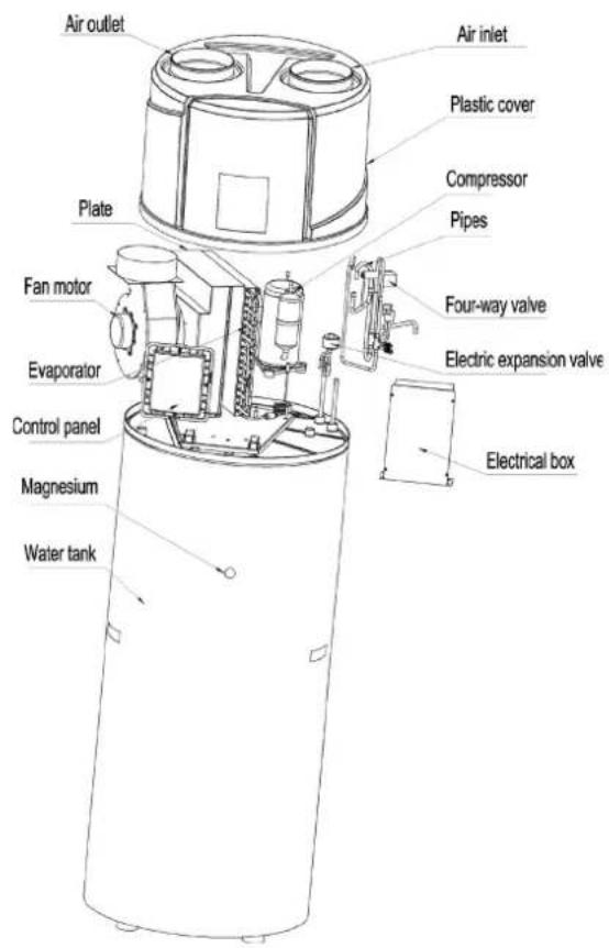
HTW-ATS-O-500VAW
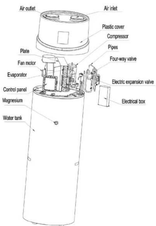
Dimensions
Model: HTW-ATS-O-***VAW
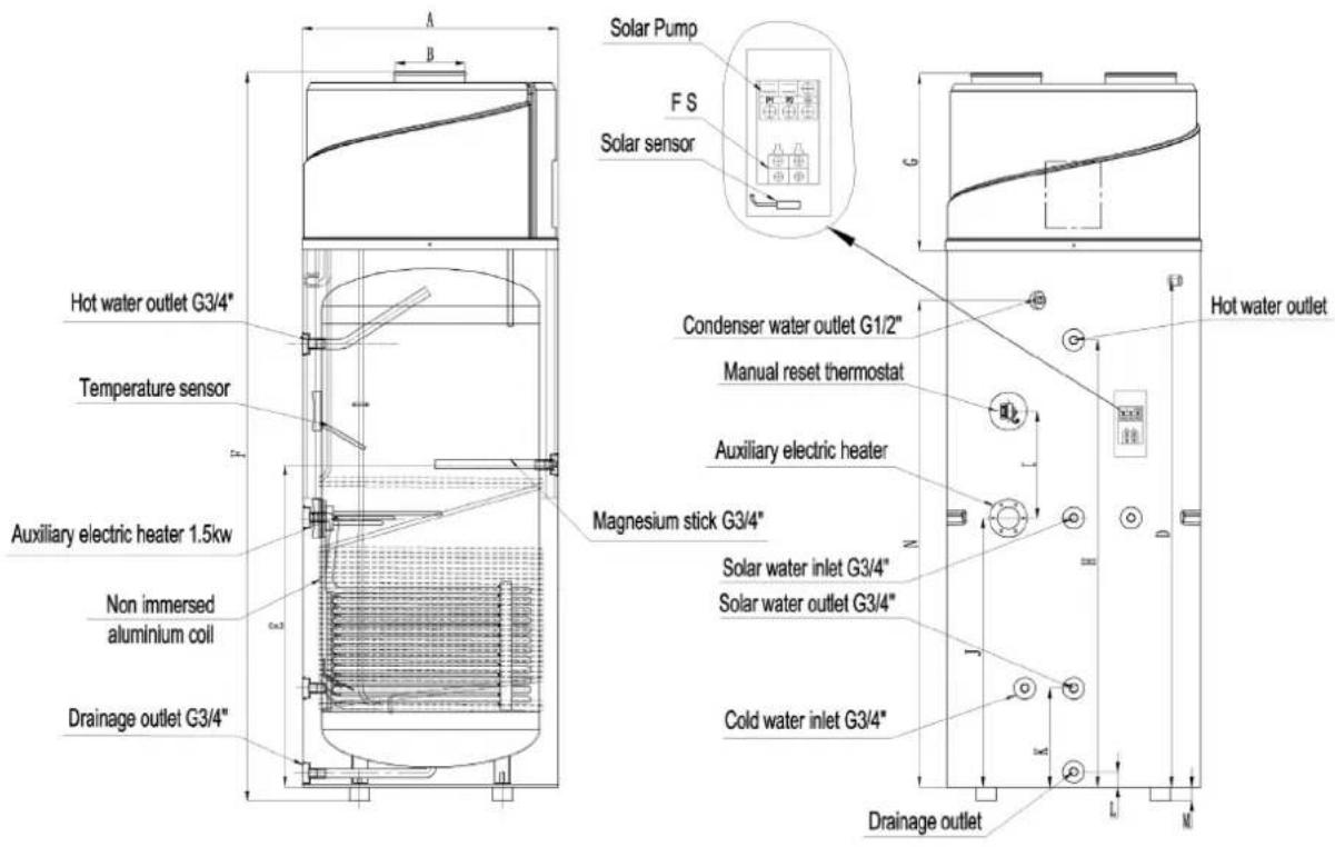
| 150L/150LS | 200L/200LS | 300L/300LS | 500L/500LS | |
| A | Φ560 | Φ560 | Φ640 | Φ700 |
| B | Φ177 | Φ177 | Φ177 | Φ177 |
| D | 946 | 1185 | 1280 | 1680 |
| E | 553 | 875 | 1040 | 1420 |
| F | 1489 | 1750 | 1845 | 2250 |
| G | 450 | 450 | 450 | 450 |
| H | 737 | 1025 | 1140 | 1520 |
| I | 270 | 270 | 270 | 270 |
| J | 457 | 600 | 680 | 893 |
| K | 482 | 250 | 250 | 280 |
| L | 32.5 | 32.5 | 32.5 | 32.5 |
| M | 35 | 35 | 35 | 35 |
| N | 847 | 1135 | 1230 | 1633 |
Remark:
1) The extra heat source is optional.
2) Add the solar control. While the parameter 14=1, solar energy control is available. The terminal "TO PUMP" is connected solar energy water pump, "FS" is connected the flow switch of solar water circuit, "SOLAR SENSOR" is testing the temp of solar thermal collector.
3) The Magnesium stick is an anti-corrosion element. It is assembled in the water tank to avoid the creation of fur around the inside tank and to protect the tank, and other components. It can help to extend the life-span of the tank. Check the magnesium stick every half year and change it if it has been used out! Note: replace by professional.
How to replace the magnesium stick

- Turn the power of the unit 'OFF' and pull out the plug.
- Drain all the water out of the tank.
- Remove the old magnesium stick from the tank.
- Replace the new magnesium stick.
- Recharge the water.
Schematic overview of the water and refrigeration circuit
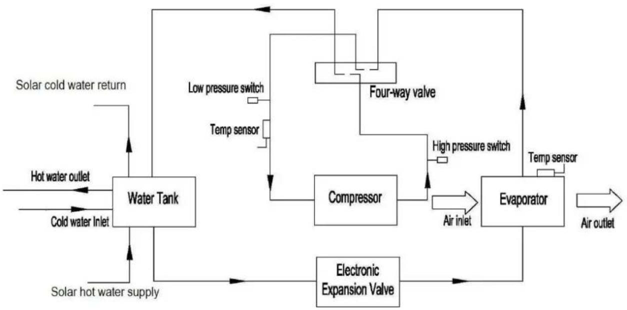
flowchart
graph TD
    A["Hot water outlet"] --> B["Water Tank"]
    C["Cold water inlet"] --> B
    B --> D["Solar hot water supply"]
    D --> E["Electric Expansion Valve"]
    E --> F["Compressor"]
    F --> G["Evaporator"]
    G --> H["Air outlet"]
    I["Solar cold water return"] --> B
    J["Low pressure switch"] --> F
    K["Temp sensor"] --> F
    L["Four-way valve"] --> F
    M["High pressure switch"] --> G
    N["Temp sensor"] --> G
    O["Air inlet"] --> G
    P["Solar hot water supply"] --> B
Choose the suitable unit
Please refer to the table below to choose the suitable unit.
| Family members | Tank capacity |
| 2 ~ 3 people | 150L |
| 4 ~ 5 people | 200L |
| 6~ 7 people | 300L |
| More than 8 people | 500L |
Note: The table is just for reference.
INSTALLATION

WARNING
- Asked your supplier to install the unit. Incomplete installation performed by yourself may result in a water leakage, electric shock, or fire.
■ Indoor installation is highly recommended. It is not allowed to install the unit at outdoor or rain achieving place.
■ The installation place without direct sunlight and other heat supplies is recommended. If no way to avoid these, please install a covering.
■ The unit must be securely fixed to avoid noise and shaking. - Make sure that there’s no obstacle around the unit.
In the place where there is strong wind, fix the unit in the locationprotected from the wind.
Transportation
As a rule, the unit is to be stored and/or transported in its shipping container in upright position and without water charge. For a transport over short distance (provided that it is done with care), an inclination angle up to 30 degrees is permitted, both during transport and storage. Ambient temperatures of -20 to +70 degrees Celsius are permitted.
- Transport using a forklift
When transported by a forklift, the unit must remain mounted on the pallet. The lifting rate should be kept to a minimum. Due to its top-heaviness, the unit must be secured against tipping over. To prevent any damage, the unit must be placed on a level surface.
- Manual transport
For the manual transport, a wooden/plastic pallet can be used. Using ropes or carrying straps, a second or third handling configuration is possible. With this type of handling, it is advised that the maximum permissible inclination angle of 45 degree is not exceeded. If transport in an inclined position cannot be avoided, the unit should be taken into operation one hour after it has been moved into final position.
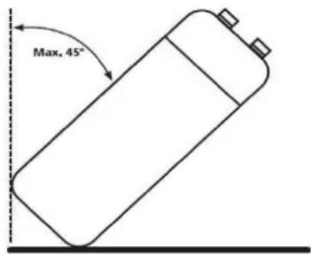

ATTENTION: DUE TO THE HIGH CENTER OF GRAVITY, LOW OVERTURNING
MOMENT, THE UNIT MUST BE SECURED AGAINST TIPPING OVER.
Required service space
Below you will find the minimum space required to be able to complete service and maintenance tasks on the units.
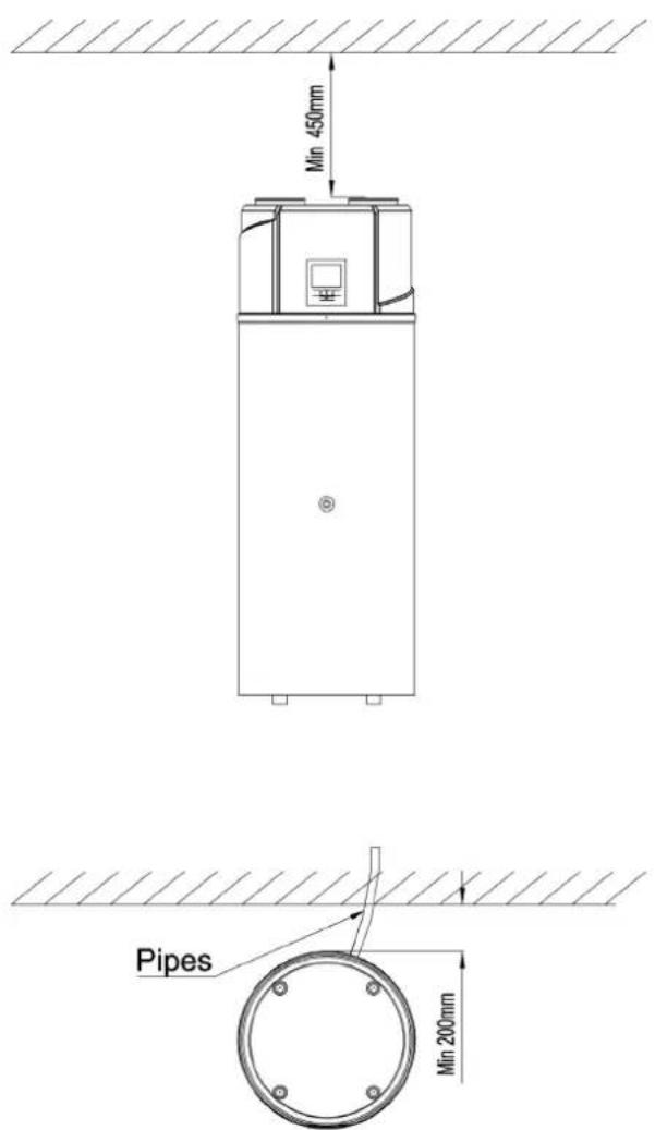
Note:
- If air inlet and/or outlet pipes are connected, portion airflow and capacity in heat pump unit will lose.
- If the unit connects with air ducts it should be DN 180mm for pipes or 180mm internal diameter flexible hose. Total length of the ducts should not be longer than 8m or the maximum static pressure should not exceed than 60Pa. Be in mind of bending site of the duct no more than 4m.
- The air outlet pipe needs to be insulated to prevent condensate condensation
Installation overview
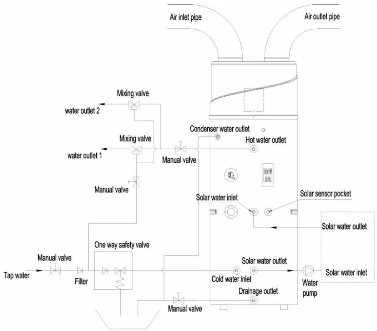
flowchart
graph TD
    Tap["Tap water"] -->|Manual valve| Filter["Filter"]
    Filter --> One_way_safety_valve["One way safety valve"]
    One way_safety_valve --> Manual_valve["Manual valve"]
    Manual_valve --> MixedValve["Mixing valve"]
    MixedValve --> Water_outlet1["Water outlet 1"]
    MixedValve --> Water_outlet2["Water outlet 2"]
    MixedValve --> Water_outlet3["Water outlet 3"]
    MixedValve --> MixedValve2["Mixing valve"]
    MixedValve --> MixedValve1["Manual valve"]
    MixedValve --> MixedValve2["Manual valve"]
    MixedValve --> MixedValve1["Manual valve"]
    MixedValve --> MixedValve3["Manual valve"]
    MixedValve --> MixedValve4["Manual valve"]
    MixedValve4 --> Condenser_2["Condenser water outlet"]
    Condenser_2 --> Hot_water_outlet["Hot water outlet"]
    Condenser_2 --> Solar_sensor_pocket["Solar sensor pocket"]
    Solar_sensor_pocket --> Solar_water_outlet["Solar water outlet"]
    Solar_sensor_pocket --> Solar_water_inlet["Solar water inlet"]
    Solar_water_inlet --> Water_pump["Water pump"]
    Solar_water_inlet --> Cold_water_inlet["Cold water inlet"]
    Solar_water_inlet --> Drainage_outlet["Drainage outlet"]
    Air_inlet_pipe["Air inlet pipe"] --> Condenser_2
    Air_outlet_pipe["Air outlet pipe"] --> Condenser_2
    Air_inlet_pipe --> Condenser_2
    Air_inlet_pipe --> Air_outlet_pipe
    Air_inlet_pipe --> Air_sensor_pocket
    Air_inlet_pipe --> Air_sensor_pocket
Note: Solar heat exchange coil is optional.

ATTENTION:
- The PT valve must be installed to release pressure. If not, it could cause damage to the unit, or even hurt people
- The one-way safety valve must be installed. If not, it could cause damage to the unit, or even hurt people. The set point of this safety valve is 0.7 MPa. For the installation place please refer to the pipeline connection sketch.
-
The condensate water drainage pipe should be installed in a continuously downward direction and in a frost-free environment.
-
The water may drip from the discharge pipe of the one-way safety valve and that this pipe must be left open to the atmosphere.
- The one-way safety valve is to be operated regularly to remove lime deposits and to verify that it is not blocked. Please beware of burn, because of the high temperature of water.
- The tank water can be drained through the drainage hole on the bottom of the tank.
- After all the pipes installed turn on the cold water inlet and hot water outlet to fill the tank. When there is water normally following out from water outlet, the tank is full. Turn off all valves and check all pipes. If any leakage, please repair.
- If the inlet water pressure is less than 0.15MPa, a pressure pump should be installed at the water inlet. For ensure the long safety using age of tank at the condition of water supply hydraulic higher than 0.7MPa, a reducing valve should be mounted at the water inlet pipe.
- Filters are needed in the air inlet. If the unit is connected with ducts, filter in there must be put forward to the air inlet of duct.
- To fluently drain condensate water from evaporator, please install the unit at the horizontal floor. Otherwise, please make sure the drain vent is at the lowest place. Recommending the inclination angle of unit to be ground should no more than 2 degree.
Installation positions
(1) Waste heat can be useful heat
Units can be installed near the kitchen, in the boiler-room or the garage, basically in every room which has a large number of waste-heat so that the unit has the higher energy efficiency even with very low outside temperatures during the winter.
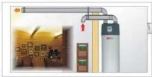
natural_image
Illustration of a gasifier or cooling unit with pipes and control panel, no visible text or symbols(2) Hot water and dehumidification
Units can be placed in the laundry room or clothing room. When it produces hot water it lowers the temperature and dehumidifies the room as well. The advantages can be experienced particularly in the humid season.
natural_image
Illustration of a laundry setup with a refrigerator, clothes hanging, a table, and a washing machine (no text or symbols)(3) Solar panel or external heat pump could be the second heat source
Units can work with solar panel, external heat pump, boiler or other different energy source.
NOTE:
· Choose the right path to move the unit.
· This unit complies with the relevant technical standards of electrical equipment.
Water loop connection
Please pay attention to the below points when connecting the water loop pipe:
- Try to reduce the water loop resistance
- Make sure there is nothing in the pipe and the water loop is smooth, check the pipe carefully to see if there is any leak, and then pack the pipe with the insulation.
- Install the one way valve and safety valve in the water circulation system according to scratch on page 12. The specification of the one way safety value is 0.7Mpa. Make sure the direction marked on the valve align with the water flow direction.
- The nominal pipe wide of the field- installed sanitary installations must be selected on the basis of the available water pressure and the expected pressure drop within the piping system.
- The water pipes may be of the flexible type. To prevent corrosion damage, make sure that the materials used in the piping system are compatible.
- When installing the pipe-work on the customers' site, any contamination of the piping system must be avoided.
Water affusion and water emptying
Water Affusion:
If the unit is used for the first time or used again after emptying the tank, please make sure that the tank is full of water before turning on the power.
- Open the cold water inlet and hot water outlet.
- Start the water affusion. When there is water normally flowing out from the hot water outlet, the tank is full.
- Turn off the hot water outlet valve and water affusion is finished.

ATTENTION: Operation without water in water tank may result in damage of auxiliary
e-heater!
Water emptying:
If the unit needs cleaning, moving etc, the tank should be emptied.
- Close the cold water inlet
- Open the hot water outlet and open the manual valve of drainpipe
- Start the water emptying.
- After emptying, close the manual valve.
Wire connection
• The specification of the power supply wire is 3 × 1.5 mm^2 .
• Fuse specification is T 3.15A 250V
- There must be a switch when connecting the unit to the power system. The current of the switch is 16A.
- The unit must be installed a Creepage Breaker near the power supply and must be effectively earthed. The specification of the creepage breaker is 30mA, less than 0.1sec.
THE APPLIANCE SHALL BE INSTALLED IN ACCORDANCE WITH NATIONAL WIRING REGULATIONS.
Trial running
Checks before trial running
- Check both the water in the tank as well as the water pipe connection.
- Check the power system, make sure that the power supply is normal and the wire connection is ok.
- Check the inlet water pressure, make sure that the pressure is sufficient (above 0.15Mpa).
- Check if any water flows out from the hot water outlet, make sure that the tank is full of water before turning on the power.
- Check the unit; make sure everything is ok before turning 'ON' the power of the unit, check the light on the wire controller when the unit runs.
- Use the wire controller to start the unit.
- Listen to the unit carefully when turning 'ON' the power of the unit. Turn the power 'OFF' when you hear an abnormal sound.
• Measure the water temperature, to check the undulation of the water temperature. - Once the parameters have been set, the user cannot change the parameters optionally. Please use a qualified service person to do this.
OPERATION THE UNIT
User interface and operation
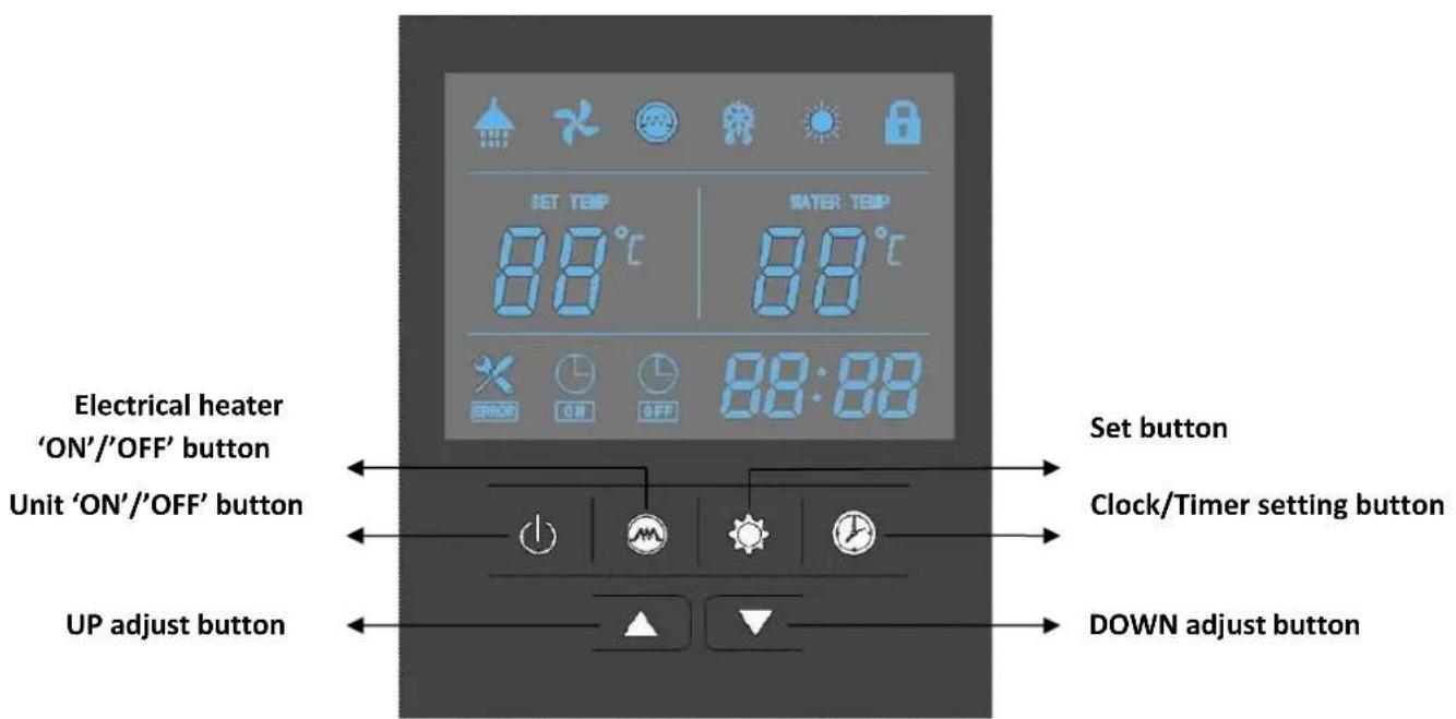
Operations
1. Power 'ON'
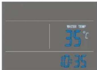
When turning 'ON' the power, whole icons are displayed on the controller screen for 3 seconds. After checking if everything is ok, the unit enters into the standby mode.
2. button
Press this button and keep for 2 seconds when the unit is standby, the unit can be turned 'ON'. Press this button and keep for 2 seconds when the unit is running, the unit can be turned 'OFF'. Short press this button to entry or exit the parameter setting or checking.
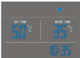
3. ▲ And ▼ buttons
- These are the multi-purpose buttons. They are used for the temp setting, parameter setting, parameter checking, clock adjustment and adjustment of the timer.
- During running status, press ▲ or ▼ button to adjust the setting temperature directly.
- Press these buttons when the unit is on clock setting status, the hour(s) and the minute(s) of the clock time can be adjusted.
- Press these buttons when the unit is on timer setting status, the hour(s) and the minute(s) of the timer 'ON'/'OFF' can be adjusted.
- Press ▲ and ▼ buttons at the same time and hold for 5 seconds, the buttons are locked.
- Press ▲ and ▼ buttons at the same time and hold for 5 seconds again, the buttons are unlocked.
4. button
Clock setting:
- After power on, short press 📋 button to entry the clock setting interface, hour and minute icons "88:88" flash together;
- Short press 📋 button to switch hour/minute setting, press the ▲ and ▼ buttons to set the exact hour(s) and minute(s);
- Press 📁 button again to confirm and exit.
Timer setting:
- After power on, long press 📋 button for 5 seconds to entry the timer setting interface, the timer on icon and hour icon "88:" flash together;
- Press the ▲ and ▼ buttons to set the exact hour(s).
- Press 🔒 button to transfer to minute setting, minute icon ":88" flash, press the ▲ and ▼ buttons to set the exact minute(s).
- Press 📋 button again to transfer to timer off setting, the timer off icon and hour icon "88:" flash together.
- Press the ▲ and ▼ buttons to set the exact hour(s).
- Press 📋 button to transfer to minute setting, minute icon “:88” flash, press the ▲ and ▼ buttons to set the exact minute(s).
- Press button again to save and exit the timer setting interface.
Press 🙏 button to cancel the timer settings during the timer 'ON' (or timer 'OFF') programming.
NOTE:
1) The timer 'ON' and timer 'OFF' functions can be set at the same time.
2) The timer settings are repeating.
3) The timer settings are still valid after a sudden power cut.
6. button
1) When the heat pump is ON, press this button to turn 'ON' the electrical heater. The heater icon 📂 will be showed, and the electrical heater will work according to the control program (parameter 3).
2) When the heat pump is ON, press this button and hold for 5 seconds to enable or disable the fan ventilation function.
3) When the heat pump is OFF, press this button to entry E-heater heating mode.
7. button
1) Check the temperatures and EXV open steps(running parameter)
-Press this button to entry temp and EXV open step checking.
-Press the ▲ and ▼ buttons to check the temp sensor values and EXV open steps (parameters A-H).
2) Check the system parameters
-In any status, press this button and hold for 5 seconds, entry the system parameter checking interface.
-Press the ▲ and ▼ buttons to check the system parameters.
3) Adjust the system parameters
- When the unit is off, press 🙏 for 5 seconds, entry the parameter checking interface.
- Press ▲ or ▼ button to select the parameter, and press ⚙ button to confirm it.
- Press the ▲ and ▼ buttons to adjust the selecting parameter, then press ⚙ to confirm the setting.
- When the unit is off, press ⚙️ for 5 seconds, entry the parameter checking interface. - Press ▲ or ▼ button to select the parameter, and press ⚙️ button to confirm it. - Press the ▲ and ▼ buttons to adjust the selecting parameter, then press ⚙️ to confirm the setting.
If no action to the buttons for 10 seconds, the controller will exit and save the setting automatically.
NOTE: The parameters have been set; the user cannot change the parameters optionally. Please ask a qualified service person to do this when required.
8. Error codes
During standby or running status, if there is a malfunction, the unit will stop automatically and show the error code on the left screen of the controller.
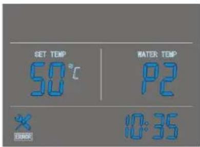
LED icons
1. Hot water available
The icon indicates that the domestic hot water temperature reaches the set point. The hot water is available for use. Heat pump is standby.
2. Fan ventilation
The icon indicates that the fan ventilation function is enabled.
When the unit is on, press the 📄 button and hold it for 5 seconds the fan ventilation function can be enabled or disabled. If this function is enabled the fan will continue working to ventilate the air, when the water temperature reaches the set point and unit is standby. If this function is disabled the fan will stop, when the water temperature reaches the set point and unit is standby.
3. Electrical heating
The icon indicates that the electrical heating function is enabled. The electrical heater will work according to the control program.
4. Defrosting
this icon shows the heat pump is under defrosting
5. Heating
this icon shows the heat pump is working
6. Key lock
The icon indicates the key lock function is enabled. The keys cannot be operated until this function is disabled.
7. Left temperature display

The display shows the setting water temperature.
When checking or adjusting the parameters, this section will display the relating parameter number.
8. Right temperature display

The display shows the current downside temperature of the water tank.
When checking or adjusting the parameters, this section will display the related parameter value.
In case any malfunction occurs, this section will display the related error code.
9. Time display

The display shows the clock time or timer time.
10. Timer 'ON'
The icon indicates that the timer 'ON' function is enabled.
11. Timer 'OFF'
The icon indicates that the timer 'OFF' function is enabled.
12. Error
The icon indicates there is malfunction.
WIFI
Install the App
Method I:
Scan the QR code to download the App, Smart Life-Smart Living, for iOS system and Android system. Finish the download and install it.
Notes: Please scan the QR code by browser for Android system.

Method 2:
Search the App, Smart Life-Smart Living, in App store for iOS system or in Google Play Store for Android system. Finish the download and install it.

flowchart
graph LR
    A["App icon"] -->|Search 'Smart Life-Smart Living'| B["House icon"]
    C["App icon"] -->|Search 'Smart Life-Smart Living'| D["House icon"]
Register
Open the App.
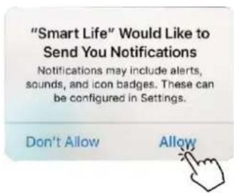
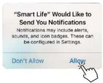
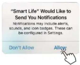
After click "Allow", enter next interface.
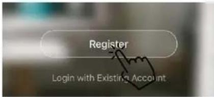
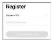
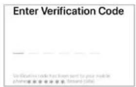
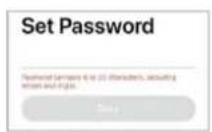
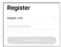
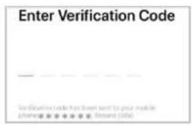
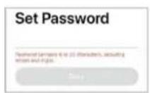
Click "Agree". Choose country and type mobile number or email address to get the message of verification code. Please set the password, and remember it.
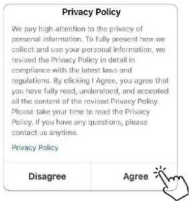
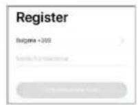
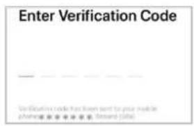
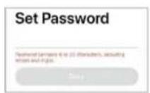
App configuration
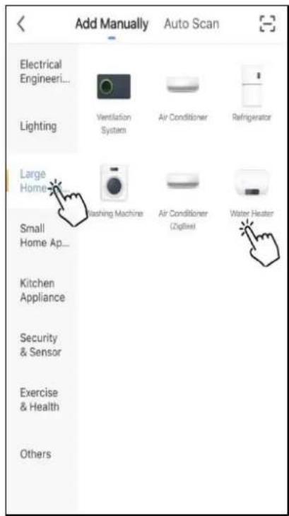
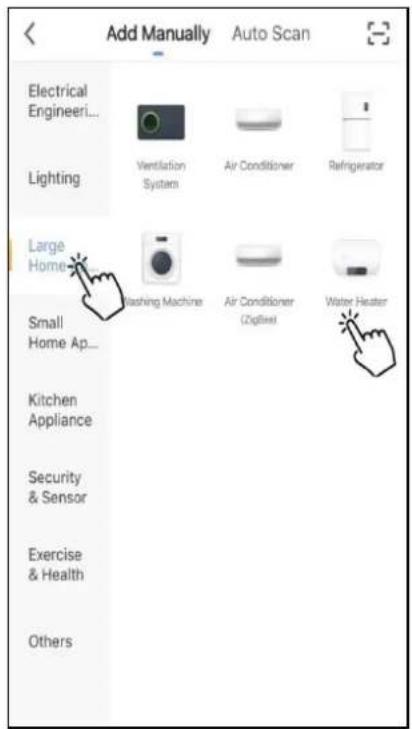
After setting the password to log in the app, add the device. Click "Large Home Applications" and "Water Heater" to next interface.
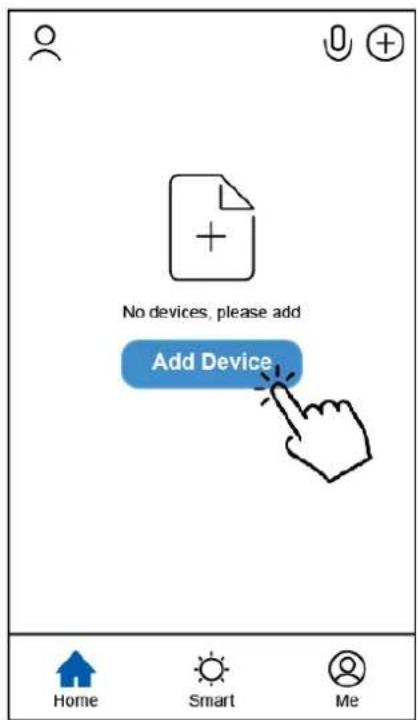
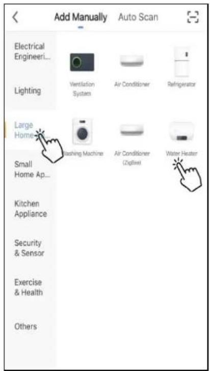
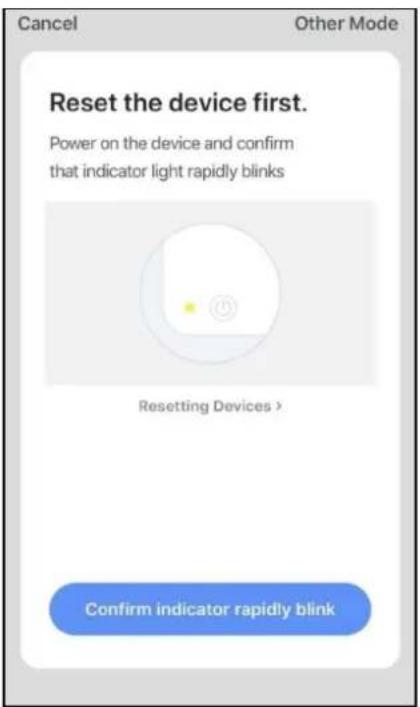
Please connect the Wi-Fi module with heat pump unit. At the same time, please keep the module and mobile devices can receive the same networks.
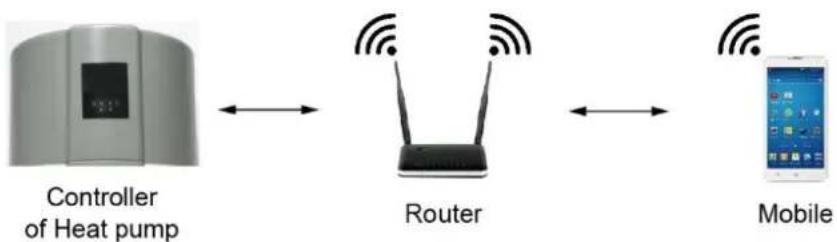
flowchart
graph LR
    A["Controller of Heat pump"] <--> B["Router"]
    B <--> C["Mobile"]
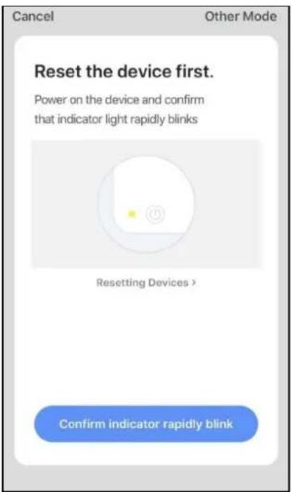
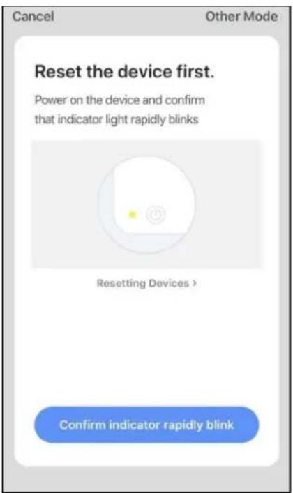
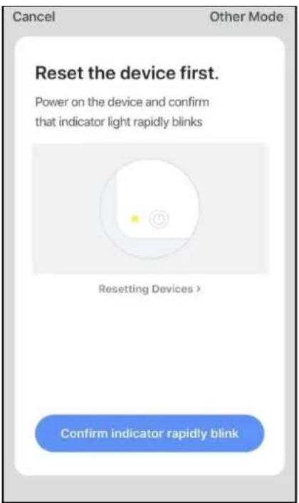
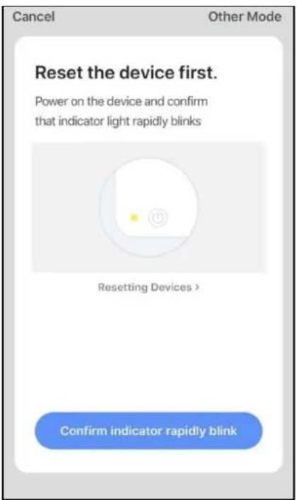
Power on the heat pump unit, and keep pressing the timer button and the increase button at the same time for 5 seconds. The SET 🔊 icon will be flashed. When the Wi-Fi indicator keeps fast-flashing, please click the "Confirm indicator rapidly blink".
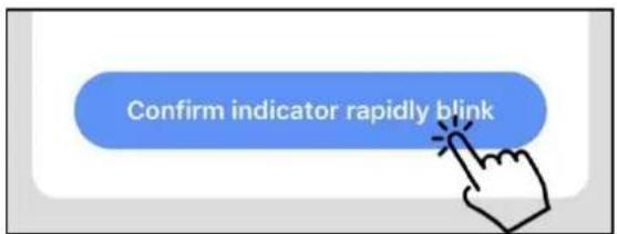
Notes: when the icon of set flashes quickly, it means the controller is in the Wi-Fi mode. When it flashes slowly, it means the controller is connecting with the App. During the connection, if the icon of set is extinguished, it means the App connection with the unit is finished.
If the mobile is not connected with Wi-Fi from the router, the interface will be automatically skipped to the following interface.

Click "go to connect" to set the mobile's Wi-Fi.
If the mobile is already connected with the Wi-Fi from the router, please type the password and click "Confirm" in the next interface.
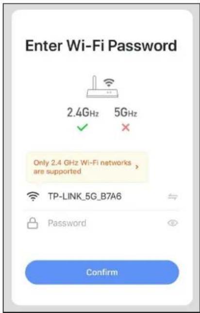
After click "Confirm", the Wi-Fi module, mobile device and Wi-Fi router begin to be connected. Finsih the connecting, and the interface will be skipped to the next interface.
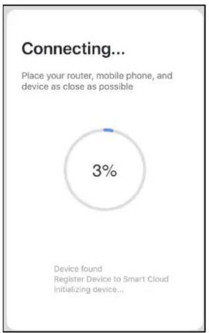
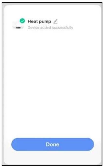
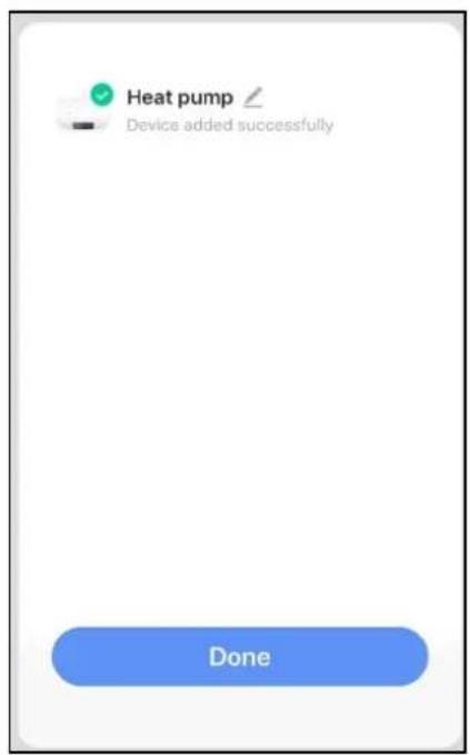
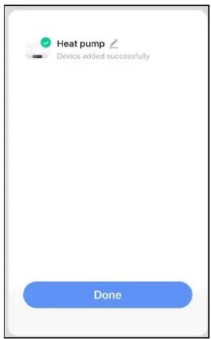
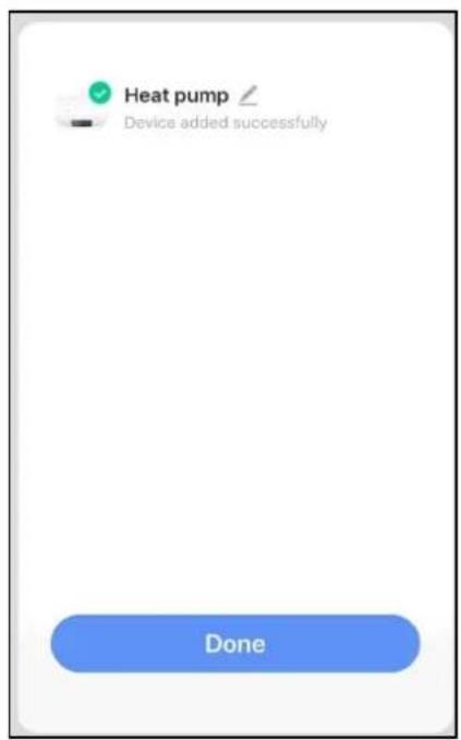
In this interface, the device (heat pump unit) can be named as you want. Click "Done" to finish the App installation. The screen of the mobile device will display the app control interface.
App operation
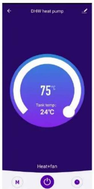

1. Modify button
Click it to enter the modify interface.
2. Temperature setting bar
Move the ball to left or right by finger to set the setting temperature.
3. 75^ Setting temperature value
This value will be changed according to the location of the ball in the temperature setting bar.
Tank temp:
- 24°C Water temperature value in the tank.
This value is detected by the water temperature sensor in the water tank.
5. Ⓜ Mode button
Click the mode button to enter the mode interface. In the mode interface, two modes including heating mode and heating fan mode can be selected.
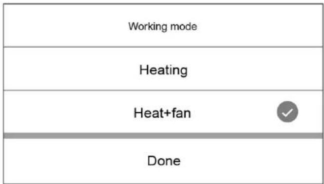
flowchart
graph TD
    A["Working mode"] --> B["Heating"]
    B --> C["Heat+fan"]
    C --> D["Done"]
- Auto Mode Running mode icon of the ehat pumpunit
According to the mode selection, this icon will display Auto Mode, Cooling Mode and Heating Mode.
- Timer button
Press this button to enter timer interface.
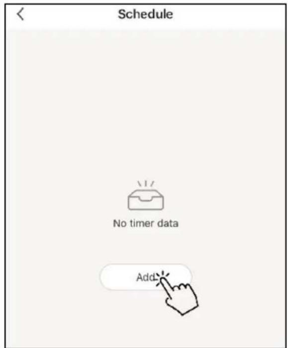
Click "Add" to set the schedule.
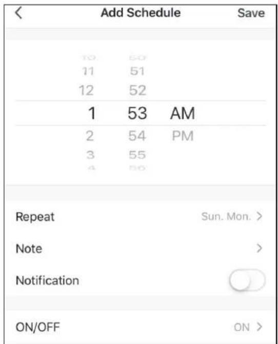
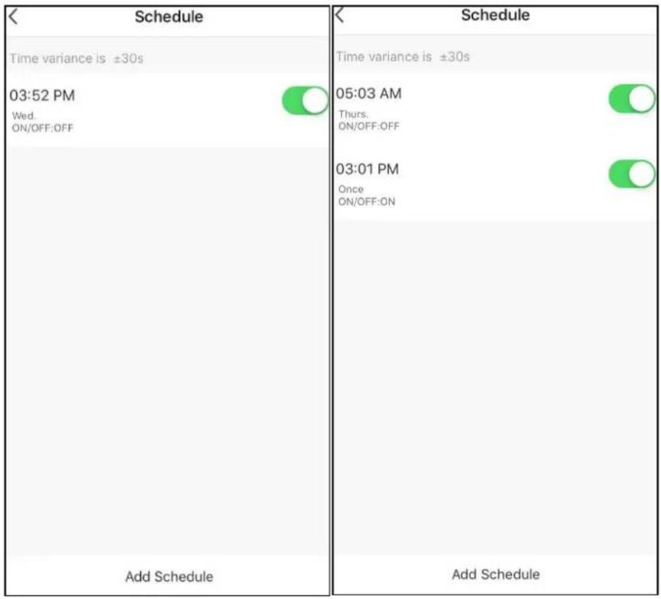
Please in this interface, setting the time and day for timer on and timer off. After setting, please click "Save" to confirm and save. The timer setting will be displayed in next interface. In this interface, click "Add Schedule" to add another timer on/off.
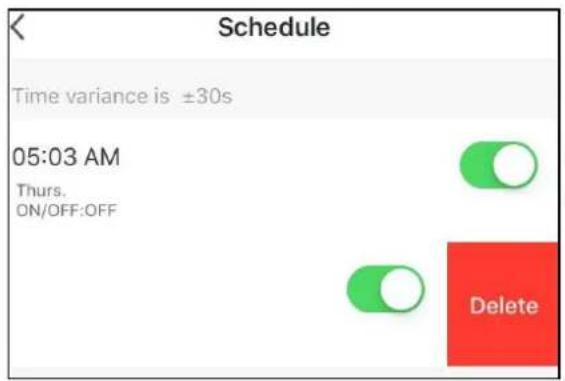
Slide the schedule from left to right to delete the schedule.
- ⏻ On/Off button
Click this button to switch on or switch off the heat pump unit.
PARAMETER CHECKING AND ADJUSTMENT
Parameter list
Some system parameters can be checked and adjusted by the controller. Below is the parameter list:
| Parameter No. | Description Range Default | Remarks | ||
| 0 | Tank water setting temp. | 10 ~ 70°C | 50°C | Adjustable |
| 1 | Water temperature gap to restart | 2 ~ 15°C | 5°C | Adjustable |
| 2 | E-heater off tank water temp | 10 ~ 85°C | 55°C | Adjustable |
| 3 | E-heater delay time | 0 ~ 90min | 6 | t * 5 min |
| 4 | Week disinfection temperature | 50 ~ 70°C | 70°C | Adjustable |
| 5 | High temp disinfection time | 0 ~ 90 min | 30 min | Adjustable |
| 6 | Defrosting period | 30~90 min | 45 min | Adjustable |
| 7 | Defrosting entry coil temp. | -30 ~ 0°C | -7°C | Adjustable |
| 8 | Defrosting exit coil temp. | 2 ~ 30°C | 13°C | Adjustable |
| 9 | Max defrosting cycle period | 1 ~ 12 min | 8 min | Adjustable |
| 10 | Electronic expansion valve adjustment | 0/1 | 1 | Adjustable (0-manual, 1-auto) |
| 11 | Target over-heat degree | -9 ~ 9°C | 5°C | Adjustable |
| 12 | Steps of manually adjusting the electronic expansion valve | 10 ~ 50 step | 35 step | Adjustable |
| 13 | Disinfection start up time adjusting | 0~23 | 23 | Adjustable(hour) |
| 14 | Parameter of solar water pump | 0/1 | 0 | Adjustable( 0 without water pump, 1with water pump) |
| 15 | Solar water pump star return difference | 2-20°C | 10 Adjustable | |
| 16 | High temp disinfection frequency | 7-28day 7 | Adjustable | |
| 17 | Temperature setting method | 0/1 1 | ||
| 18 | Set temperature when light source is present (PV is on) | 10 ~ 70°C | 60 | |
| 19 | Set temperature when no light source (PV is alternating) | 10 ~ 70°C | 50 | |
| A | Inlet water temp. sensor detect range | -9 ~ 99°C | Actual testing value. Error code P1 will be shown in case of a malfunction | |
| B | Outlet water temp. sensor detect range | -9 ~ 99°C | Actual testing value. Error code P2 will be shown in case of a malfunction | |
| C | Evaporator coil temp. sensor detect range | -9 ~ 99°C | Actual testing value. Error code P3 will be shown in case of a malfunction | |
| D | Return gas temp. sensor detect range | -9 ~ 99°C | Actual testing value. Error code PP4 will be shown in case of a malfunction | |
| E | Ambient temp. sensor detect range | -9 ~ 99°C | Actual testing value. Error code PP5 will be shown in case of a malfunction | |
| F | Electronic expansion valve step | -9 ~ 99°C | N*10 step | |
| H | Temp of solar thermal collector | 0-140°C | Measured value, if failure, show P6 | |
Malfunctioning of the unit and error codes
When an error occurs or the protection mode is set automatically, the circuit board and the wired controller will both display the error message.
| Protection/Malfunction | Error code | LED indicator | Possible reasons Corrective actions |
| Standby | Dark | ||
| Normal running | Bright | ||
| Lower tank water temp. sensor failure | P1 | ☆●(1flash 1 dark) | 1) The sensor open circuit2) The sensor short circuit3) PCB board failure |
| Upper tank water temp. sensor failure | P2 | ☆☆●(2 flashes 1 dark) | 1) The sensor open circuit2) The sensor short circuit3) PCB board failure |
| Evaporator coil temp. sensor failure | P3 | ☆☆☆●(3 flashes 1 dark) | 1) The sensor open circuit2) The sensor short circuit3) PCB board failure |
| Return air temp sensor failure | P4 | ☆☆☆☆●(4 flashes 1 dark) | 1) The sensor open circuit2) The sensor short circuit3) PCB board failure |
| Ambient | P5 | ☆☆☆☆☆ | 1) The sensor open |
| temp. sensor failure | ●(5 flashes 1 dark) | circuit2) The sensor short circuit3) PCB board failure | connection2) Replace the sensor3) change the PCB board | |
| Solar temp. sensor failure | P6 | ☆☆☆☆☆☆☆☆☆☆☆● (10 flash1dark) | 1) The sensor open circuit2) The sensor short circuit3) PCB board failure | 1) Check the sensor connection2) Replace the sensor3) change the PCB board |
| Emergency switch off | EC | only show the protection code | 1) Connecting wire off2) PCB board failure | 1) According to the physical truth judging whether is normal or not2) change the PCB board |
| High pressure protection (HP Switch) | E1 | ☆☆☆☆☆☆●(6 flashes 1 dark) | 1) Too high air inlet temp2) Less water in the tank3) The electronic expansion valve assembly blocked4) Too much refrigerant5) The switch damaged6) The uncompressed gas is in refrigerant system7) PCB board failure | 1) Check if the air inlet temp is over the working limited2) Check if the tank is full of water. If not, charge water3) Replace the electronic expansion valve assembly4) Discharge some refrigerant5) Replace a new switch6) Discharge and then recharge the refrigerant7) change the PCB board |
| Low pressure protection (LP Switch) | E2 | ☆☆☆☆☆☆☆●(7 flashes 1 dark) | 1) Too low air inlet temp2) The electronic expansion valve assembly blocked3) Too less refrigerant4) The switch damaged5) The fan assembly can not work6 PCB board failure | 1) Check if the air inlet temp is over the working limited2) Replace the electronic expansion valve assembly3) Charge some refrigerant4) Replace a new switch5) Check if the fan working when the compressor working. If not, some problems with the fan assembly6) change the PCB board |
| Over heat protection (HTP Switch) | E3 | ☆☆☆☆☆☆☆☆●(8 flashes 1 dark) | 1) Too high tank water temp2) The switch damaged3) PCB board failure | 1) If the tank water temp is over 85C, the switch will open and the unit will stop for protection. After the water comes to normal temp,2) Replace a new switch3) Change the PCB board |
| Solar thermal collector high tem protection | E4 | ☆☆☆☆☆☆☆☆☆☆☆☆●(11flash1 dark) | 1) solar water circuit water flow very little or without water flow2) Related connecting wires off3) Water pump failure4) PCB board failure | 1) Solar water circuit fluid infusion and exhaust2) Related connecting wires being reconnected3) Change the water pump4) change the PCB board |
| Water flow failure | E5 | ☆☆☆☆☆☆☆☆☆●(9 flash 1dark) | 1) solar water circuit water flow very little or without water flow2) Related connecting wires off3) water pump failure4) water flow switch failure5) PCB board failure | 1) Solar water circuit fluid infusion and exhaust2) Related connecting wires being reconnected3) Change the water pump4) Change the water flow switch5) Change the PCB board |
| Defrost | Defrosting indicate | ☆☆☆☆☆☆☆......( all long flashes) | ||
| Communication failure | E8 | Bright |
MAINTENANCE
Maintenance activities
In order to ensure an optimum operation of the unit, a number of checks and inspections on the unit and the field wiring have to be carried out at regular intervals, preferably yearly.
➢ Check the water supply and air vent frequently, to avoid lack of water or air in the water loop.
Clean the water filter to keep a good water quality. Lack of water and dirty water can damage the unit.
Keep the unit in a place where it is dry and clean, and which has good ventilation. Clean the heat exchanger every one to two months.
➢ Check each part of the unit and the pressure of the system. Replace the defect part if there is any, and recharge the refrigerant if it is required.
➢ Check the power supply and the electrical system, make sure the electrical components are good, and the wiring is well. If there is a damaged part or a strange smell, please replace it in time.
If the heat pump is not used for a long time, please drain out all the water from the unit and seal the unit to keep it good. Please drain the water from the lowest point of the boiler to avoid freezing in winter. Water recharge and full inspection on the heat pump is required before it is restarted.
Do not turn the power 'OFF' when you use the unit continuously, or the water in the pipe will freeze and split the pipe.
Keep the unit clean by means of soft damp cloth, no maintenance is required by the operator.
It is recommended to clean the tank and e-heater regularly to keep an efficient performance.
Generally no maintenance is required by the operator, except below: It is recommended to set a lower temperature to decrease the heat release, prevent scale and save energy if the outlet water is sufficient. Keep the unit clean by means of soft damp cloth.
TROUBLESHOOTING
This section provides useful information for diagnosing and correcting certain troubles which may occur. Before starting the troubleshooting procedure, carry out a thorough visual inspection of the unit and look for obvious defects such as loose connections or defective wiring.
Before contacting your local dealer, read this chapter carefully, it will save you time and money.

WHEN CARRYING OUT AN INSPECTION ON THE SWITCH BOX OF THE UNIT, ALWAYS MAKE SURE THAT THE MAIN SWITCH OF THE UNIT IS SWITCHED 'OFF'.
The guidelines below might help to solve your problem. If you cannot solve the problem, consult your installer/local dealer.
No image on the controller (blank display). Check if the main power is still connected.
One of the error codes appears, consult your local dealer.
The scheduled timer does work but the programmed actions are executed at the wrong time (e.g. 1 hour too late or too early). Check if the clock and the day of the week are set correctly, adjust if necessary.
ENVIRONMENTAL INFORMATION
This equipment contains fluorinated greenhouse gases covered by the Kyoto Protocol. It should only be serviced or dismantled by professional trained personnel.
This equipment contains R134a refrigerant in the amount as stated in the specification. Do not vent R134a into the atmosphere: R134a, is a fluorinated greenhouse gas with a Global Warming Potential (GWP) = 1430.
DISPOSAL REQUIREMENTS
Dismantling of the unit, treatment of the refrigerant, of oil and of other parts must be done in accordance with relevant local and national legislation.
Your product is marked with this symbol. This means that electrical and electronic products shall not be mixed with unsorted household waste.
Do not try to dismantle the system yourself: the dismantling of the system, treatment of the refrigerant, of oil and other parts must be done by a qualified installer in accordance with relevant local and national legislation.
Units must be treated at a specialized treatment facility for re-use, recycling and recovery. By ensuring that this product is disposed off correctly, you will help to prevent potential negative consequences for the environment and human health. Please contact the installer or local authority for more information.
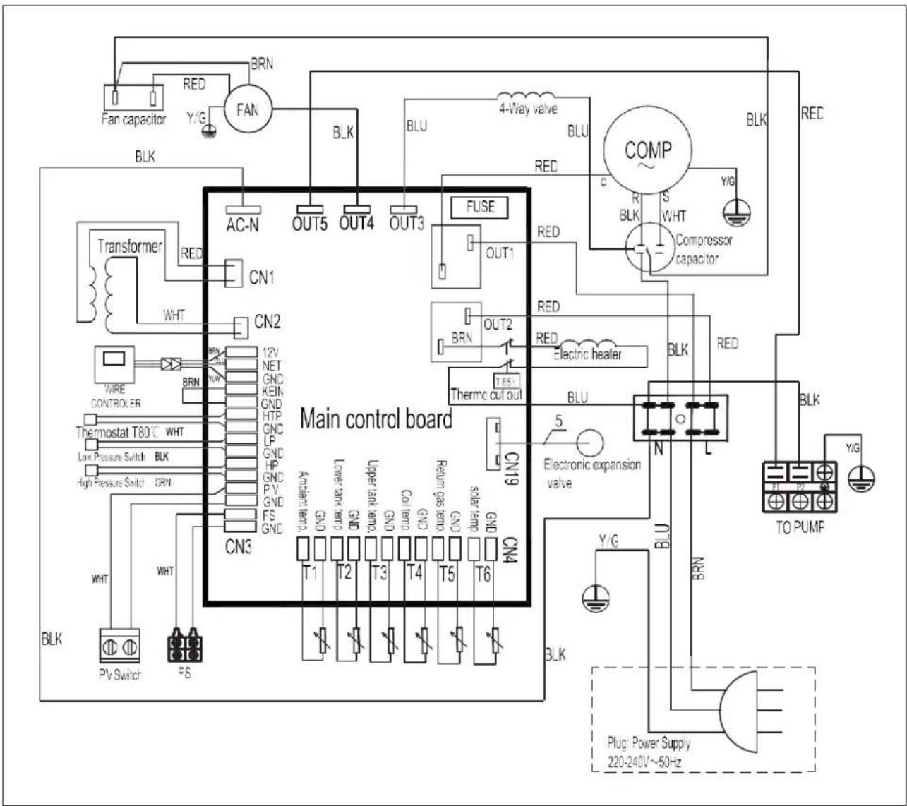
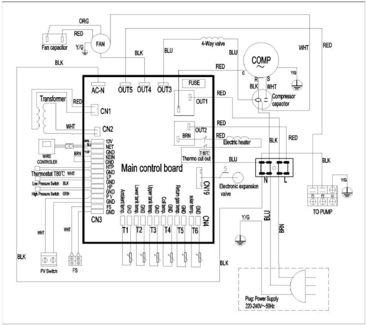
WIRING DIAGRAM
Please refer to the wiring diagram on the electric box.
HTW-ATS-O-150/200/300VAW (S)
TECHNICAL SPECIFICATION
| TECHNICAL DATA | 150L | 150LS | 200L | 200LS | 300L | 300LS | 500L | 500LS | |
| Power supply | V/Ph/Hz | 220-240 / 1/50 | |||||||
| Water tank Volume L | 150 | 200 | 300 | 500 | |||||
| Max power input W | 700 + 1600(e-heater) | 1,420 + 1,600(e-heater) | |||||||
| Max current | A | 3.2+ 6.8 (e-heater) | 6.2+6.8 (e-heater) | ||||||
| Max.outlet water temperature range(without using E-heater) | °C | 60 | |||||||
| Max. water temperature | °C | 70 | |||||||
| Min. water temperature | °C | 1 | |||||||
| Ambient working temp. | °C | -5-43 | |||||||
| Max. discharge pressure | bar | 20 | |||||||
| Min. suction pressure | bar | 6 | |||||||
| Refrigerant type | R134a | ||||||||
| Compressor | Type | Rotary | |||||||
| Brand | GMCC | ||||||||
| Model | PJ125G1C-4DZDE | PJ250M2C-4FT | |||||||
| Fan motor | Type | asynchronous motor | |||||||
| W | 80 | 194 | |||||||
| RPM | 1280 | 1430 | |||||||
| Air flow | m3/h | 450 | 900 | ||||||
| Duct diameter mm | 177 (Fit flexible 180/200mm duct) | ||||||||
| Max allowed pressure of tank | bar | 10 | |||||||
| Inside body material of tank | SUS 304 | ||||||||
| Auxiliary electrical heater | kW | 1,6 (incoloy825) | |||||||
| Electronic expansion valve | yes | ||||||||
| Magnesium stick | yes | ||||||||
| Solar heat exchanger | N/A | SUS316~ 1m2 | N/A | SUS316~ 1m2 | N/A | SUS316~ 1m2 | N/A | SUS316~ 1m2 | |
| Hot water outlet | inch | G 1 | |||||||
| Solar heat source inlet/outlet | inch | G 3/4 | |||||||
| Cold water inlet | inch | G 1 | |||||||
| Drainage | inch | G 3 / 4 | |||||||
| Condensed water outlet | inch G 1 / 2 | ||||||||
| Heat pump heat exchanger material | Aluminium alloy | ||||||||
| Net Dimensions | mm | 560x1490 | 560x1750 | 640x1845 | 700x2250 | ||||
| Packing Dimensions | mm | 615x615x1610 | 615x615x1870 | 695x695x1965 | 750x750x2355 | ||||
| Net Weight | Kg | 86 | 93 | 90 | 97 | 97 | 104 | 115 | 122 |
| Gross Weight | Kg | 90 | 97 | 94 | 101 | 101 | 108 | 120 | 127 |
| Noise level | dB(A) | 46 48 | |||||||
| NOTES:* During disinfection, the max water temp could be up to 70^ by electrical heater | |||||||||
TEMPERATURE SENSOR R-T CONVERSION TABLE
R25= 5.0KΩ±1.0% B25-50 = 3470K±1.0%
| °C | Rmin /KΩ | KΩ | Rmax/ KΩ | °C | Rmin /KΩ | KΩ | Rmax/ KΩ | °C | Rmin /KΩ KΩ | Rmax/ | KΩ |
| -20 | 36.195 | 37.303 | 38.441 | 21 | 5.779 | 5.847 | 5.914 | 62 | 1.343 | 1.374 | 1.406 |
| -19 | 34.402 | 35.437 | 36.499 | 22 | 5.558 | 5.62 | 5.683 | 63 | 1.301 | 1.331 | 1.362 |
| -18 | 32.709 | 33.676 | 34.668 | 23 | 5.346 | 5.404 | 5.463 | 64 | 1.26 | 1.29 | 1.321 |
| -17 | 31.109 | 32.012 | 32.939 | 24 | 5.144 | 5.198 | 5.252 | 65 | 1.221 | 1.25 | 1.28 |
| -16 | 29.597 | 30.441 | 31.306 | 25 | 4.95 | 5 | 5.05 | 66 | 1.183 | 1.212 | 1.242 |
| -15 | 28.168 | 28.957 | 29.765 | 26 | 4.761 | 4.811 | 4.861 | 67 | 1.147 | 1.175 | 1.204 |
| -14 | 26.816 | 27.554 | 28.308 | 27 | 4.58 | 4.63 | 4.68 | 68 | 1.111 | 1.139 | 1.168 |
| -13 | 25.538 | 26.227 | 26.932 | 28 | 4.408 | 4.457 | 4.507 | 69 | 1.077 | 1.105 | 1.133 |
| -12 | 24.328 | 24.972 | 25.631 | 29 | 4.242 | 4.292 | 4.341 | 70 | 1.045 | 1.072 | 1.099 |
| -11 | 23.183 | 23.785 | 24.4 | 30 | 4.084 | 4.133 | 4.182 | 71 | 1.013 | 1.04 | 1.067 |
| -10 | 22.098 | 22.661 | 23.236 | 31 | 3.933 | 3.981 | 4.03 | 72 | 0.983 | 1.009 | 1.035 |
| -9 | 21.071 | 21.598 | 22.135 | 32 | 3.788 | 3.836 | 3.885 | 73 | 0.953 | 0.979 | 1.005 |
| -8 | 20.098 | 20.59 | 21.093 | 33 | 3.649 | 3.697 | 3.745 | 74 | 0.925 | 0.95 | 0.975 |
| -7 | 19.176 | 19.636 | 20.106 | 34 | 3.516 | 3.563 | 3.611 | 75 | 0.897 | 0.922 | 0.947 |
| -6 | 18.301 | 18.732 | 19.171 | 35 | 3.388 | 3.435 | 3.483 | 76 | 0.871 | 0.895 | 0.919 |
| -5 | 17.472 | 17.875 | 18.285 | 36 | 3.266 | 3.313 | 3.36 | 77 | 0.845 | 0.869 | 0.893 |
| -4 | 16.686 | 17.063 | 17.446 | 37 | 3.149 | 3.195 | 3.241 | 78 | 0.82 | 0.843 | 0.867 |
| -3 | 15.94 | 16.292 | 16.65 | 38 | 3.037 | 3.082 | 3.128 | 79 | 0.796 | 0.819 | 0.842 |
| -2 | 15.231 | 15.561 | 15.896 | 39 | 2.929 | 2.974 | 3.019 | 80 | 0.773 | 0.795 | 0.818 |
| -1 | 14.559 | 14.867 | 15.18 | 40 | 2.826 | 2.87 | 2.915 | 81 | 0.751 | 0.773 | 0.795 |
| 0 | 13.92 | 14.208 | 14.501 | 41 | 2.726 | 2.77 | 2.815 | 82 | 0.729 | 0.751 | 0.773 |
| 1 | 13.313 | 13.582 | 13.856 | 42 | 2.631 | 2.675 | 2.718 | 83 | 0.708 | 0.729 | 0.751 |
| 2 | 12.736 | 12.988 | 13.244 | 43 | 2.54 | 2.583 | 2.626 | 84 | 0.688 | 0.709 | 0.73 |
| 3 | 12.188 | 12.423 | 12.662 | 44 | 2.452 | 2.494 | 2.537 | 85 | 0.668 | 0.689 | 0.709 |
| 4 | 11.666 | 11.887 | 12.11 | 45 | 2.368 | 2.409 | 2.451 | 86 | 0.649 | 0.669 | 0.69 |
| 5 | 11.17 | 11.376 | 11.585 | 46 | 2.287 | 2.328 | 2.369 | 87 | 0.631 | 0.651 | 0.671 |
| 6 | 10.698 | 10.891 | 11.086 | 47 | 2.209 | 2.25 | 2.29 | 88 | 0.613 | 0.632 | 0.652 |
| 7 | 10.249 | 10.429 | 10.611 | 48 | 2.135 | 2.174 | 2.214 | 89 | 0.596 | 0.615 | 0.634 |
| 8 | 9.822 | 9.99 | 10.16 | 49 | 2.063 | 2.102 | 2.141 | 90 | 0.579 | 0.598 | 0.617 |
| 9 | 9.414 | 9.572 | 9.73 | 50 | 1.994 | 2.032 | 2.071 | 91 | 0.563 | 0.581 | 0.6 |
| 10 | 9.027 | 9.173 | 9.321 | 51 | 1.927 | 1.965 | 2.003 | 92 | 0.548 | 0.566 | 0.584 |
| 11 | 8.657 | 8.794 | 8.932 | 52 | 1.863 | 1.901 | 1.938 | 93 | 0.533 | 0.55 | 0.568 |
| 12 | 8.305 | 8.432 | 8.561 | 53 | 1.802 | 1.839 | 1.876 | 94 | 0.518 | 0.535 | 0.553 |
| 13 | 7.969 | 8.088 | 8.208 | 54 | 1.743 | 1.779 | 1.815 | 95 | 0.504 | 0.521 | 0.538 |
| 14 | 7.648 | 7.76 | 7.872 | 55 | 1.686 | 1.721 | 1.757 | 96 | 0.49 | 0.507 | 0.524 |
| 15 | 7.343 | 7.446 | 7.551 | 56 | 1.631 | 1.666 | 1.701 | 97 | 0.477 | 0.493 | 0.51 |
| 16 | 7.051 | 7.148 | 7.245 | 57 | 1.579 | 1.613 | 1.647 | 98 | 0.464 | 0.48 | 0.496 |
| 17 | 6.773 | 6.863 | 6.953 | 58 | 1.528 | 1.561 | 1.595 | 99 | 0.452 | 0.467 | 0.483 |
| 18 | 6.507 | 6.5911 | 6.675 | 59 | 1.479 | 1.512 | 1.545 | 100 | 0.439 | 0.455 | 0.47 |
| 19 | 6.253 | 6.331 | 6.41 | 60 | 1.432 | 1.464 | 1.497 | ||||
| 20 | 6.011 | 6.083 | 6.156 | 61 | 1.386 | 1.418 | 1.451 |
TEMPERATURE SENSOR R-T CONVERSION TABLE
Only use for the solar temp sensor
R 25=50KΩ±1.0% B 25/50 = 3950K±1.0%
| °C | R(cent) | °C | R(cent) | °C | R(cent) | °C | R(cent) |
| -20 | 466.6 | 15 | 78.38 | 50 | 17.93 | 85 | 5.227 |
| -19 | 441.1 | 16 | 74.85 | 51 | 17.26 | 86 | 5.061 |
| -18 | 417.2 | 17 | 71.5 | 52 | 16.61 | 87 | 4.902 |
| -17 | 394.7 | 18 | 68.32 | 53 | 15.99 | 88 | 4.748 |
| -16 | 373.5 | 19 | 65.29 | 54 | 15.4 | 89 | 4.6 |
| -15 | 353.6 | 20 | 62.41 | 55 | 14.83 | 90 | 4.457 |
| -14 | 334.8 | 21 | 59.68 | 56 | 14.29 | 91 | 4.319 |
| -13 | 317.2 | 22 | 57.07 | 57 | 13.77 | 92 | 4.188 |
| -12 | 300.6 | 23 | 54.6 | 58 | 13.27 | 93 | 4.058 |
| -11 | 284.9 | 24 | 52.24 | 59 | 12.79 | 94 | 3.935 |
| -10 | 270.2 | 25 | 50 | 60 | 12.33 | 95 | 3.815 |
| -9 | 256.3 | 26 | 47.86 | 61 | 11.89 | 96 | 3.7 |
| -8 | 243.1 | 27 | 45.83 | 62 | 11.46 | 97 | 3.589 |
| -7 | 230.7 | 28 | 43.89 | 63 | 11.06 | 98 | 3.482 |
| -6 | 219 | 29 | 42.05 | 64 | 10.67 | 99 | 3.378 |
| -5 | 208 | 30 | 40.28 | 65 | 10.29 | 100 | 3.278 |
| -4 | 197.6 | 31 | 38.61 | 66 | 9.936 | 101 | 3.182 |
| -3 | 187.7 | 32 | 37.01 | 67 | 9.591 | 102 | 3.088 |
| -2 | 178.4 | 33 | 35.49 | 68 | 9.259 | 103 | 2.998 |
| -1 | 169.6 | 34 | 34.03 | 69 | 8.941 | 104 | 2.911 |
| 0 | 161.3 | 35 | 32.65 | 70 | 8.635 | 105 | 2.827 |
| 1 | 153.4 | 36 | 31.32 | 71 | 8.341 | 106 | 2.746 |
| 2 | 146 | 37 | 30.06 | 72 | 8.058 | 107 | 2.667 |
| 3 | 139 | 38 | 28.85 | 73 | 7.786 | 108 | 2.591 |
| 4 | 132.3 | 39 | 27.7 | 74 | 7.525 | 109 | 2.517 |
| 5 | 126 | 40 | 26.6 | 75 | 7.247 | 110 | 2.446 |
| 6 | 120 | 41 | 25.55 | 76 | 7.032 | 111 | 2.378 |
| 7 | 114.3 | 42 | 24.54 | 77 | 6.8 | 112 | 2.311 |
| 8 | 109 | 43 | 23.58 | 78 | 6.576 | 113 | 2.247 |
| 9 | 103.9 | 44 | 22.66 | 79 | 6.361 | 114 | 2.184 |
| 10 | 99.04 | 45 | 21.78 | 80 | 6.153 | 115 | 2.124 |
| 11 | 94.47 | 46 | 20.94 | 81 | 5.954 | 116 | 2.065 |
| 12 | 90.12 | 47 | 20.14 | 82 | 5.762 | 117 | 2.009 |
| 13 | 86 | 48 | 19.37 | 83 | 5.577 | 118 | 1.955 |
| 14 | 82.09 | 49 | 18.64 | 84 | 5.398 | 119 | 1.902 |
FRANÇAIS
MANUEL DE L'UTILISATEUR ET D'INSTALLATION
CHAUFFE-EAU THERMODYNAMIQUE
VAW
HTW-ATS-O-150VAW | HTW-ATS-O-200VAW
HTW-ATS-O-300VAW | HTW-ATS-O-500VAW
TABLE DES MATIÈRES
INTRODUCTION....88
Ce manuel....88
L'unité....88
CONSIGNES DE SÉCURITÉ 89
Attention....89
Mise en garde 91
LES POINTS À L'INTÉRIEUR DU PRODUIT. 92
APERÇU DE L'UNITÉ....93
natural_image
Illustration of an industrial HVAC system with pipes and control panel (no visible text or symbols)natural_image
Illustration of a laundry setup with clothes hanging, air purifier, table, and washing machine (no text or symbols)3.
Et
The image is too blurry to recognize any text content.
Icônes LED
Méthode 2:
flowchart
graph LR
    A["App icon"] -->|Search 'Smart Life-Smart Living'| B["House icon"]
    C["App icon"] -->|Search 'Smart Life-Smart Living'| D["House icon"]
Record
flowchart
graph TD
    A["Working mode"] --> B["Heating"]
    B --> C["Heat+fan"]
    C --> D["Done"]
- ⏻ Bouton ON/OFF
R 25=50KΩ±1.0% B 25/50 = 3950K±1.0%
| °C | R(cent) | °C | R(cent) | °C | R(cent) | °C | R(cent) |
| -20 | 466.6 | 15 | 78.38 | 50 | 17.93 | 85 | 5.227 |
| -19 | 441.1 | 16 | 74.85 | 51 | 17.26 | 86 | 5.061 |
| -18 | 417.2 | 17 | 71.5 | 52 | 16.61 | 87 | 4.902 |
| -17 | 394.7 | 18 | 68.32 | 53 | 15.99 | 88 | 4.748 |
| -16 | 373.5 | 19 | 65.29 | 54 | 15.4 | 89 | 4.6 |
| -15 | 353.6 | 20 | 62.41 | 55 | 14.83 | 90 | 4.457 |
| -14 | 334.8 | 21 | 59.68 | 56 | 14.29 | 91 | 4.319 |
| -13 | 317.2 | 22 | 57.07 | 57 | 13.77 | 92 | 4.188 |
| -12 | 300.6 | 23 | 54.6 | 58 | 13.27 | 93 | 4.058 |
| -11 | 284.9 | 24 | 52.24 | 59 | 12.79 | 94 | 3.935 |
| -10 | 270.2 | 25 | 50 | 60 | 12.33 | 95 | 3.815 |
| -9 | 256.3 | 26 | 47.86 | 61 | 11.89 | 96 | 3.7 |
| -8 | 243.1 | 27 | 45.83 | 62 | 11.46 | 97 | 3.589 |
| -7 | 230.7 | 28 | 43.89 | 63 | 11.06 | 98 | 3.482 |
| -6 | 219 | 29 | 42.05 | 64 | 10.67 | 99 | 3.378 |
| -5 | 208 | 30 | 40.28 | 65 | 10.29 | 100 | 3.278 |
| -4 | 197.6 | 31 | 38.61 | 66 | 9.936 | 101 | 3.182 |
| -3 | 187.7 | 32 | 37.01 | 67 | 9.591 | 102 | 3.088 |
| -2 | 178.4 | 33 | 35.49 | 68 | 9.259 | 103 | 2.998 |
| -1 | 169.6 | 34 | 34.03 | 69 | 8.941 | 104 | 2.911 |
| 0 | 161.3 | 35 | 32.65 | 70 | 8.635 | 105 | 2.827 |
| 1 | 153.4 | 36 | 31.32 | 71 | 8.341 | 106 | 2.746 |
| 2 | 146 | 37 | 30.06 | 72 | 8.058 | 107 | 2.667 |
| 3 | 139 | 38 | 28.85 | 73 | 7.786 | 108 | 2.591 |
| 4 | 132.3 | 39 | 27.7 | 74 | 7.525 | 109 | 2.517 |
| 5 | 126 | 40 | 26.6 | 75 | 7.247 | 110 | 2.446 |
| 6 | 120 | 41 | 25.55 | 76 | 7.032 | 111 | 2.378 |
| 7 | 114.3 | 42 | 24.54 | 77 | 6.8 | 112 | 2.311 |
| 8 | 109 | 43 | 23.58 | 78 | 6.576 | 113 | 2.247 |
| 9 | 103.9 | 44 | 22.66 | 79 | 6.361 | 114 | 2.184 |
| 10 | 99.04 | 45 | 21.78 | 80 | 6.153 | 115 | 2.124 |
| 11 | 94.47 | 46 | 20.94 | 81 | 5.954 | 116 | 2.065 |
| 12 | 90.12 | 47 | 20.14 | 82 | 5.762 | 117 | 2.009 |
| 13 | 86 | 48 | 19.37 | 83 | 5.577 | 118 | 1.955 |
| 14 | 82.09 | 49 | 18.64 | 84 | 5.398 | 119 | 1.902 |
PORTUGUÊS
DIAGRAMA ELÉCTRICO....165
ESPECIFICAÇÕES TÉCNICAS 167
HTW-ATS-O-***VAW 167
SENSOR DE TEMPERATURA R-T TABELA DE CONVERSÃO ....169

natural_image
Illustration of a smart air purifier system with control panel and sensor array (no text or symbols)natural_image
Illustration of a laundry setup with a washing machine, table, and clothes hanging on a line (no text or symbols)(3) Painel Solar ou bomba de calor externo poderia ser a segunda fonte de calor
2. Botão
3. Botões e ▼
Ícones LCD
Método 2:
flowchart
graph LR
    A["App icon"] -->|Search 'Smart Life-Smart Living'| B["House icon"]
    C["App icon"] -->|Search 'Smart Life-Smart Living'| D["House icon"]
Registro
Abra o aplicativo.
pie
Connecting... Place your router, mobile phone, and device as close as possible | Device found | | :--- | | Register Device to Smart Cloud Initializing device... |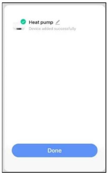
flowchart
graph TD
    A["Working mode"] --> B["Heating"]
    B --> C["Heat+fan"]
    C --> D["Done"]
- ⏻ Botão ON/OFF
R 25=50KΩ±1.0% B 25/50 = 3950K±1.0%
| °C | R(cent) | °C | R(cent) | °C | R(cent) | °C | R(cent) |
| -20 | 466.6 | 15 | 78.38 | 50 | 17.93 | 85 | 5.227 |
| -19 | 441.1 | 16 | 74.85 | 51 | 17.26 | 86 | 5.061 |
| -18 | 417.2 | 17 | 71.5 | 52 | 16.61 | 87 | 4.902 |
| -17 | 394.7 | 18 | 68.32 | 53 | 15.99 | 88 | 4.748 |
| -16 | 373.5 | 19 | 65.29 | 54 | 15.4 | 89 | 4.6 |
| -15 | 353.6 | 20 | 62.41 | 55 | 14.83 | 90 | 4.457 |
| -14 | 334.8 | 21 | 59.68 | 56 | 14.29 | 91 | 4.319 |
| -13 | 317.2 | 22 | 57.07 | 57 | 13.77 | 92 | 4.188 |
| -12 | 300.6 | 23 | 54.6 | 58 | 13.27 | 93 | 4.058 |
| -11 | 284.9 | 24 | 52.24 | 59 | 12.79 | 94 | 3.935 |
| -10 | 270.2 | 25 | 50 | 60 | 12.33 | 95 | 3.815 |
| -9 | 256.3 | 26 | 47.86 | 61 | 11.89 | 96 | 3.7 |
| -8 | 243.1 | 27 | 45.83 | 62 | 11.46 | 97 | 3.589 |
| -7 | 230.7 | 28 | 43.89 | 63 | 11.06 | 98 | 3.482 |
| -6 | 219 | 29 | 42.05 | 64 | 10.67 | 99 | 3.378 |
| -5 | 208 | 30 | 40.28 | 65 | 10.29 | 100 | 3.278 |
| -4 | 197.6 | 31 | 38.61 | 66 | 9.936 | 101 | 3.182 |
| -3 | 187.7 | 32 | 37.01 | 67 | 9.591 | 102 | 3.088 |
| -2 | 178.4 | 33 | 35.49 | 68 | 9.259 | 103 | 2.998 |
| -1 | 169.6 | 34 | 34.03 | 69 | 8.941 | 104 | 2.911 |
| 0 | 161.3 | 35 | 32.65 | 70 | 8.635 | 105 | 2.827 |
| 1 | 153.4 | 36 | 31.32 | 71 | 8.341 | 106 | 2.746 |
| 2 | 146 | 37 | 30.06 | 72 | 8.058 | 107 | 2.667 |
| 3 | 139 | 38 | 28.85 | 73 | 7.786 | 108 | 2.591 |
| 4 | 132.3 | 39 | 27.7 | 74 | 7.525 | 109 | 2.517 |
| 5 | 126 | 40 | 26.6 | 75 | 7.247 | 110 | 2.446 |
| 6 | 120 | 41 | 25.55 | 76 | 7.032 | 111 | 2.378 |
| 7 | 114.3 | 42 | 24.54 | 77 | 6.8 | 112 | 2.311 |
| 8 | 109 | 43 | 23.58 | 78 | 6.576 | 113 | 2.247 |
| 9 | 103.9 | 44 | 22.66 | 79 | 6.361 | 114 | 2.184 |
| 10 | 99.04 | 45 | 21.78 | 80 | 6.153 | 115 | 2.124 |
| 11 | 94.47 | 46 | 20.94 | 81 | 5.954 | 116 | 2.065 |
| 12 | 90.12 | 47 | 20.14 | 82 | 5.762 | 117 | 2.009 |
| 13 | 86 | 48 | 19.37 | 83 | 5.577 | 118 | 1.955 |
| 14 | 82.09 | 49 | 18.64 | 84 | 5.398 | 119 | 1.902 |
ITALIANO
SCHEMA CABLAGGIO....208
SPECIFICHE TECNICHE 210
HTW-ATS-O-***VAW 210
natural_image
Illustration of a gasifier or cooling unit with a piping system and control panel, no visible text or symbolsnatural_image
Illustration of a laundry setup with a washing machine, table, and clothes hanging on a line (no text or symbols)Nota:
2.

3.

Icone LCD
Metodo 2:
flowchart
graph LR
    A["App icon"] -->|Search 'Smart Life-Smart Living'| B["House icon"]
    C["Game icon"] -->|Search 'Smart Life-Smart Living'| D["House icon"]
Registrazione
flowchart
graph TD
    A["Working mode"] --> B["Heating"]
    B --> C["Heat+fan"]
    C --> D["Done"]
R 25=50KΩ±1.0% B 25/50 = 3950K±1.0%
| °C | R(cent) | °C | R(cent) | °C | R(cent) | °C | R(cent) |
| -20 | 466.6 | 15 | 78.38 | 50 | 17.93 | 85 | 5.227 |
| -19 | 441.1 | 16 | 74.85 | 51 | 17.26 | 86 | 5.061 |
| -18 | 417.2 | 17 | 71.5 | 52 | 16.61 | 87 | 4.902 |
| -17 | 394.7 | 18 | 68.32 | 53 | 15.99 | 88 | 4.748 |
| -16 | 373.5 | 19 | 65.29 | 54 | 15.4 | 89 | 4.6 |
| -15 | 353.6 | 20 | 62.41 | 55 | 14.83 | 90 | 4.457 |
| -14 | 334.8 | 21 | 59.68 | 56 | 14.29 | 91 | 4.319 |
| -13 | 317.2 | 22 | 57.07 | 57 | 13.77 | 92 | 4.188 |
| -12 | 300.6 | 23 | 54.6 | 58 | 13.27 | 93 | 4.058 |
| -11 | 284.9 | 24 | 52.24 | 59 | 12.79 | 94 | 3.935 |
| -10 | 270.2 | 25 | 50 | 60 | 12.33 | 95 | 3.815 |
| -9 | 256.3 | 26 | 47.86 | 61 | 11.89 | 96 | 3.7 |
| -8 | 243.1 | 27 | 45.83 | 62 | 11.46 | 97 | 3.589 |
| -7 | 230.7 | 28 | 43.89 | 63 | 11.06 | 98 | 3.482 |
| -6 | 219 | 29 | 42.05 | 64 | 10.67 | 99 | 3.378 |
| -5 | 208 | 30 | 40.28 | 65 | 10.29 | 100 | 3.278 |
| -4 | 197.6 | 31 | 38.61 | 66 | 9.936 | 101 | 3.182 |
| -3 | 187.7 | 32 | 37.01 | 67 | 9.591 | 102 | 3.088 |
| -2 | 178.4 | 33 | 35.49 | 68 | 9.259 | 103 | 2.998 |
| -1 | 169.6 | 34 | 34.03 | 69 | 8.941 | 104 | 2.911 |
| 0 | 161.3 | 35 | 32.65 | 70 | 8.635 | 105 | 2.827 |
| 1 | 153.4 | 36 | 31.32 | 71 | 8.341 | 106 | 2.746 |
| 2 | 146 | 37 | 30.06 | 72 | 8.058 | 107 | 2.667 |
| 3 | 139 | 38 | 28.85 | 73 | 7.786 | 108 | 2.591 |
| 4 | 132.3 | 39 | 27.7 | 74 | 7.525 | 109 | 2.517 |
| 5 | 126 | 40 | 26.6 | 75 | 7.247 | 110 | 2.446 |
| 6 | 120 | 41 | 25.55 | 76 | 7.032 | 111 | 2.378 |
| 7 | 114.3 | 42 | 24.54 | 77 | 6.8 | 112 | 2.311 |
| 8 | 109 | 43 | 23.58 | 78 | 6.576 | 113 | 2.247 |
| 9 | 103.9 | 44 | 22.66 | 79 | 6.361 | 114 | 2.184 |
| 10 | 99.04 | 45 | 21.78 | 80 | 6.153 | 115 | 2.124 |
| 11 | 94.47 | 46 | 20.94 | 81 | 5.954 | 116 | 2.065 |
| 12 | 90.12 | 47 | 20.14 | 82 | 5.762 | 117 | 2.009 |
| 13 | 86 | 48 | 19.37 | 83 | 5.577 | 118 | 1.955 |
| 14 | 82.09 | 49 | 18.64 | 84 | 5.398 | 119 | 1.902 |
GIAGroup
C/ Can Cabanyes, 88, Polígono Industrial Can Gordi. 08403 Granollers. Barcelona (Spain)
Tel (0034) 93 390 42 20 - Fax (0034) 93 390 42 05
info@groupgia.com - www.groupgia.com
FRANCE
info@htwfrance.com
PORTUGAL
info@htw.pt
ITALY
info.it@htwspain.com
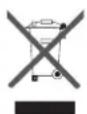
At the end of its working life, the product must not be disposed of as urban waste. It must be taken to a special local authority deifferentiated waste collection centre or to a dealer providing this service. Disposing of a household appliance separately avoids possible negative consequences for the environment and health deriving from inappropriate disposal and enables the constituent materials to be recovered to obtain significant savings in energy and resources. As a reminder of the need to dispose of household appliances separately, the product is marked with a crossed-outwheeled dustbin.
AVERTISSEMENTS POUR L'ÉLIMINATION CORRECTE DU PRODUIT AUX TERMES DE LA DIRECTIVE 2002/96 / CE.
- VAW
- NOTA:
- 3.
- y
- SAFETY INSTRUCTIONS....47
- ITEMS INSIDE PRODUCT BOX....50
- OVERVIEW OF THE UNIT....51
- INSTALLATION....54
- PARAMETER CHECKING AND ADJUSTMENT 74
- MAINTENANCE....77
- TROUBLESHOOTING....78
- ENVIRONMENTAL INFORMATION....78
- DISPOSAL REQUIREMENTS....79
- WIRING DIAGRAM....80
- TECHNICAL SPECIFICATION....82
- TEMPERATURE SENSOR R-T CONVERSION TABLE....84
- OPERATION, CONTACT YOUR DEALER FOR ADVICE AND INFORMATION.
- INTRODUCTION
- This manual
- The unit
- Waste Heat recovery
- Hot water and dehumidification
- Storage room cooling
- Hot water and fresh air ventilation
- Compatible with different energy sources
- Ecological and Economical Heating
- Compact design
- Multiple Functions
- Other features
- SAFETY INSTRUCTIONS
- Warning
- Do not install the unit yourself.
- Install the unit securely in a place.
- Caution
- Do not put your fingers or others into the fan, or evaporator.
- ITEMS INSIDE PRODUCT BOX
- OVERVIEW OF THE UNIT Parts and descriptions
- Dimensions
- Remark:
- How to replace the magnesium stick
- Schematic overview of the water and refrigeration circuit
- Choose the suitable unit
- INSTALLATION
- Transportation
- - Transport using a forklift
- - Manual transport
- Required service space
- Note:
- Installation overview
- ATTENTION:
- Installation positions
- Waste heat can be useful heat
- Hot water and dehumidification
- Solar panel or external heat pump could be the second heat source
- Water loop connection
- Water affusion and water emptying
- Water Affusion:
- Water emptying:
- Wire connection
- Trial running
- Checks before trial running
- OPERATION THE UNIT
- User interface and operation
- Operations
- Power 'ON'
- button
- ▲ And ▼ buttons
- button
- button
- button
- Error codes
- LED icons
- Hot water available
- Fan ventilation
- Electrical heating
- Defrosting
- Heating
- Key lock
- Left temperature display
- Right temperature display
- Time display
- Timer 'ON'
- Timer 'OFF'
- Error
- WIFI
- App configuration
- Modify button
- Temperature setting bar
- 75° Setting temperature value
- Tank temp:
- Ⓜ Mode button
- PARAMETER CHECKING AND ADJUSTMENT
- Parameter list
- Malfunctioning of the unit and error codes
- MAINTENANCE
- Maintenance activities
- TROUBLESHOOTING
- ENVIRONMENTAL INFORMATION
- DISPOSAL REQUIREMENTS
- WIRING DIAGRAM
- TEMPERATURE SENSOR R-T CONVERSION TABLE
- MANUEL DE L'UTILISATEUR ET D'INSTALLATION
- TABLE DES MATIÈRES
- INTRODUCTION....88
- CONSIGNES DE SÉCURITÉ 89
- LES POINTS À L'INTÉRIEUR DU PRODUIT. 92
- APERÇU DE L'UNITÉ....93
- Et
- The image is too blurry to recognize any text content.
- Icônes LED
- Botão
- Botões e ▼
- Ícones LCD
- 2.
- Icone LCD
- GIAGroup
- FRANCE
- PORTUGAL
- ITALY
Brand : HTW
Model : ATS-O-150VAW
Category : Digital SLR Camera