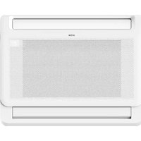
ADMIRA -MFI-46ADMR32 - Air Conditioning HTW - Free user manual and instructions
Find the device manual for free ADMIRA -MFI-46ADMR32 HTW in PDF.


| Product type | Wall-mounted split air conditioner |
| Brand | HTW |
| Model | ADMIRA -MFI-46ADMR32 |
| Cooling capacity | 12,000 BTU (approximately 3.5 kW) |
| Power supply | 220-240 V ~ 50 Hz |
| Power consumption | Approximately 1,050 W |
| Dimensions (indoor unit) | 78 x 25 x 20 cm |
| Dimensions (outdoor unit) | 70 x 50 x 28 cm |
| Weight (indoor unit) | 9 kg |
| Weight (outdoor unit) | 25 kg |
| Refrigerant | R32 |
| Noise level (indoor unit) | 42 dB(A) |
| Main functions | Cooling, heating (reversible), ventilation, dehumidification |
| Control | Remote control included |
| Filter | Washable air filter |
| Maintenance and cleaning | Clean the filter every month; have the unit checked by a professional once a year |
| Safety | Grounding mandatory; do not use an extension cord |
| Spare parts and repairability | Parts available from HTW and authorized dealers |
Frequently Asked Questions - ADMIRA -MFI-46ADMR32 HTW
User questions about ADMIRA -MFI-46ADMR32 HTW
0 question about this device. Answer the ones you know or ask your own.
Ask a new question about this device
Download the instructions for your Air Conditioning in PDF format for free! Find your manual ADMIRA -MFI-46ADMR32 - HTW and take your electronic device back in hand. On this page are published all the documents necessary for the use of your device. ADMIRA -MFI-46ADMR32 by HTW.
USER MANUAL ADMIRA -MFI-46ADMR32 HTW
OWNER'S AND INSTALLATION MANUAL
FR
MANUEL DE L'UTILISATEUR ET D'INSTALLATION
PT
Please, read carefully this manual before using the product.
• Al enfriar
• Al calentar
Ajuste la rejilla verticalmente.


Precaución

Sustituir las pilas

Make sure nothing is blocking all air inlets and outlets

PRECAUCIÓN
radio mínimo 10cm (3.9)
Safety Precautions ....46
Owner's Manual
Unit Specifications and Features....51
- Indoor unit display....
- Operating temperature....
- Other features ....
- Adjusting Air Flow Direction....54
Care and Maintenance ....55
Troubleshooting....57
Installation Manual
Accessories.... 60
Installation Summary......61
Unit Parts....62
Indoor Unit Installation....63
- Select installation location....63
2.Hang indoor unit....64 - Drill wall hole for connective piping.....
- Connect drain hose....67
Outdoor Unit Installation....68
- Select installation location....68
- Install drain joint....69
- Anchor outdoor unit....69
Refrigerant Piping Connection.... 71
A. Note on Pipe Length.... 72
B.Connection Instructions –Refrigerant Piping....72
1.Cut pipe....72
2.Remove burrs....73
3. Flare pipe ends....73
4. Connect pipes....73
Wiring....75
- Outdoor Uint Wiring....
2.Indoor Uint Wiring....77
3.Power Specifications....78
Air Evacuation....79
1.Evacuation Instructions....79
2. Note on Adding Refrigerant....80
Test Run....81
Safety Precautions
Read Safety Precautions Before Operation and Installation
Incorrect installation due to ignoring instructions can cause serious damage or injury.
The seriousness of potential damage or injuries is classified as either a WARNING or CAUTION.

WARNING
This symbol indicates the possibility of personnel injury or loss of life.

CAUTION
This symbol indicates the possibility of property damage or serious consequences.

WARNING
This appliance can be used by children aged from 8 years and above and persons with reduced physical, sensory or mental capabilities or lack of experience and knowledge if they have been given supervision or instruction concerning use of the appliance in a safe way and understand the hazards involved. Children shall not play with the appliance. Cleaning and user maintenance shall not be made by children without supervision(EN Standard requirements).
This appliance is not intended for use by persons(including children) with reduced physical, sensory or mental capabilities, or lack of experience and knowledge, unless they have been given supervision or instruction concerning use of the appliance by a person responsible for their safety. Children should be supervised to ensure that they do not play with the appliance.

WARNINGS FOR PRODUCT USE
- If an abnormal situation arises (like a burning smell), immediately turn off the unit and disconnect the power. Call your dealer for instructions to avoid electric shock, fire or injury.
- Do not insert fingers, rods or other objects into the air inlet or outlet. This may cause injury, since the fan may be rotating at high speeds.
- Do not use flammable sprays such as hair spray, lacquer or paint near the unit. This may cause fire or combustion.
- Do not operate the air conditioner in places near or around combustible gases. Emitted gas may collect around the unit and cause explosion.
- Do not operate your air conditioner in a wet room such as a bathroom or laundry room. Too much exposure to water can cause electrical components to short circuit.
- Do not expose your body directly to cool air for a prolonged period of time.
Do not allow children to play with the air conditioner. Children must be supervised around the unit at all times. - If the air conditioner is used together with burners or other heating devices, thoroughly ventilate the room to avoid oxygen deficiency.
- In certain functional environments, such as kitchens, server rooms, etc., the use of specially designed air-conditioning units is highly recommended.
CLEANING AND MAINTENANCE WARNINGS
- Turn off the device and disconnect the power before cleaning. Failure to do so can cause electrical shock.
- Do not clean the air conditioner with excessive amounts of water.
Do not clean the air conditioner with combustible cleaning agents. Combustible cleaning agents can cause fire or deformation.

CAUTION
- Turn off the air conditioner and disconnect the power if you are not going to use it for a long time.
• Turn off and unplug the unit during storms.
• Make sure that water condensation can drain unhindered from the unit. - Do not operate the air conditioner with wet hands. This may cause electric shock.
- Do not use device for any other purpose than its intended use.
- Do not climb onto or place objects on top of the outdoor unit.
- Do not allow the air conditioner to operate for long periods of time with doors or windows open, or if the humidity is very high.

ELECTRICAL WARNINGS
- Only use the specified power cord. If the power cord is damaged, it must be replaced by the manufacturer, its service agent or similarly qualified persons in order to avoid a hazard.
- Keep power plug clean. Remove any dust or grime that accumulates on or around the plug. Dirty plugs can cause fire or electric shock.
- Do not pull power cord to unplug unit. Hold the plug firmly and pull it from the outlet. Pulling directly on the cord can damage it, which can lead to fire or electric shock.
- Do not modify the length of the power supply cord or use an extension cord to power the unit.
- Do not share the electrical outlet with other appliances. Improper or insufficient power supply can cause fire or electrical shock.
• The product must be properly grounded at the time of installation, or electrical shock may occur. - For all electrical work, follow all local and national wiring standards, regulations, and the Installation Manual. Connect cables tightly, and clamp them securely to prevent external forces from damaging the terminal. Improper electrical connections can overheat and cause fire, and may also cause shock. All electrical connections must be made according to the Electrical Connection Diagram located on the panels of the indoor and outdoor units.
- All wiring must be properly arranged to ensure that the control board cover can close properly. If the control board cover is not closed properly, it can lead to corrosion and cause the connection points on the terminal to heat up, catch fire, or cause electrical shock.
- If connecting power to fixed wiring, an all-pole disconnection device which has at least 3mm clearances in all poles, and have a leakage current that may exceed 10mA, the residual current device(RCD) having a rated residual operating current not exceeding 30mA, and disconnection must be incorporated in the fixed wiring in accordance with the wiring rules.
TAKE NOTE OF FUSE SPECIFICATIONS
The air conditioner's circuit board (PCB) is designed with a fuse to provide overcurrent protection.
The specifications of the fuse are printed on the circuit board, such as :
T3.15A/250VAC, T5A/250VAC, T10A/250VAC, T20A/250VAC, T30A/250VAC, etc.
NOTE: For the units with R32 or R290 refrigerant, only the blast-proof ceramic fuse can be used.

WARNINGS FOR PRODUCT INSTALLATION
- Installation must be performed by an authorized dealer or specialist. Defective installation can cause water leakage, electrical shock, or fire.
- Installation must be performed according to the installation instructions. Improper installation can cause water leakage, electrical shock, or fire.
(In North America, installation must be performed in accordance with the requirement of NEC and CEC by authorized personnel only.) - Contact an authorized service technician for repair or maintenance of this unit. This appliance shall be installed in accordance with national wiring regulations.
- Only use the included accessories, parts, and specified parts for installation. Using non-standard parts can cause water leakage, electrical shock, fire, and can cause the unit to fail.
- Install the unit in a firm location that can support the unit's weight. If the chosen location cannot support the unit's weight, or the installation is not done properly, the unit may drop and cause serious injury and damage.
- Install drainage piping according to the instructions in this manual. Improper drainage may cause water damage to your home and property.
- For units that have an auxiliary electric heater, do not install the unit within 1 meter (3 feet) of any combustible materials.
- Do not install the unit in a location that may be exposed to combustible gas leaks. If combustible gas accumulates around the unit, it may cause fire.
- Do not turn on the power until all work has been completed.
- When moving or relocating the air conditioner, consult experienced service technicians for disconnection and reinstallation of the unit.
- How to install the appliance to its support, please read the information for details in "indoor unit installation" and "outdoor unit installation" sections.
Note about Fluorinated Gasses(Not applicable to the unit using R290 Refrigerant)
- This air-conditioning unit contains fluorinated greenhouse gasses. For specific information on the type of gas and the amount, please refer to the relevant label on the unit itself or the "Owner's Manual - Product Fiche" in the packaging of the outdoor unit.(European Union products only).
- Installation, service, maintenance and repair of this unit must be performed by a certified technician.
- Product uninstallation and recycling must be performed by a certified technician.
- For equipment that contains fluorinated greenhouse gases in quantities of 5 tonnes of CO2 equivalent or more, but of less than 50 tonnes of CO2 equivalent, If the system has a leak-detection system installed, it must be checked for leaks at least every 24 months.
- When the unit is checked for leaks, proper record-keeping of all checks is strongly recommended.

WARNING for Using R32/R290 Refrigerant
- When flammable refrigerant are employed, appliance shall be stored in a well -ventilated area where the room size corresponds to the room area as specific for operation.
For R32 frigerant models:
Appliance shall be installed, operated and stored in a room with a floor area larger than X m2 . Appliance shall not be installed in an unvertilated space, if that space is smaller than X m2 (Please see the following form).
| Model (Btu/h) | Minimum room area ( m2 ) |
| ≤18000 | 18 |
- Reusable mechanical connectors and flared joints are not allowed indoors. (EN Standard Requirements).
- Mechanical connectors used indoors shall have a rate of not more than 3g/year at 25% of the maximum allowable pressure. When mechanical connectors are reused indoors, sealing parts shall be renewed. When flared joints are reused indoors, the flare part shall be re-fabricated. (UL Standard Requirements)
- When mechanical connectors are reused indoors, sealing parts shall be renewed. When flared joints are reused indoors, the flare part shall be re-fabricated. (IEC Standard Requirements)
- Mechanical connectors used indoors shall comply with ISO 14903.
European Disposal Guidelines
This marking shown on the product or its literature, indicates that waste electrical and electrical equipment should not be mixed with general household waste.
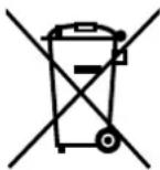
Correct Disposal of This Product
(Waste Electrical & Electronic Equipment)

This appliance contains refrigerant and other potentially hazardous materials. When disposing of this appliance, the law requires special collection and treatment. Do not dispose of this product as household waste or unsorted municipal waste.
When disposing of this appliance, you have the following options:
- Dispose of the appliance at designated municipal electronic waste collection facility.
- When buying a new appliance, the retailer will take back the old appliance free of charge.
- The manufacturer will take back the old appliance free of charge.
- Sell the appliance to certified scrap metal dealers.
Special notice
Disposing of this appliance in the forest or other natural surroundings endangers your health and is bad for the environment. Hazardous substances may leak into the ground water and enter the food chain.
Unit Specifications and Features
Indoor unit display
NOTE: This display panel on the indoor unit can be used to operate the unit in case the remote control has been misplaced or is out of batteries.

Display panel
(A) (B)
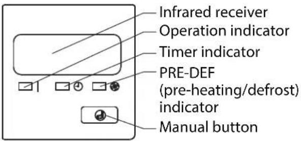

• 88 Displays temperature and Error codes:
“ dF when defrosting(for model B cooling & heating units)
" OR for 3 seconds when:
• TIMER ON is set(for model B)
• SWING or SILENCE is turned on
“ OF for 3 seconds when:
• TIMER OFF is set(for model B)
• SWING or SILENCE is turned off
“ SE when unit is self-cleaning
“FP when 8 C heating feature is turned on
MANUAL button: This button selects the mode in the following order: AUTO, FORCED COOL, OFF.
FORCED COOL mode: In FORCED COOL mode, the Operation light flashes. The system will then turn to AUTO after it has cooled with a high wind speed for 30 minutes. The remote control will be disabled during this operation.
OFF mode: The unit turns off and the remote control is re-enabled.
Operating temperature
When your air conditioner is used outside of the following temperature ranges, certain safety protection features may activate and cause the unit to disable.
Inverter Split Type
| COOL mode HEAT mode DRY mode | |||
| Room Temperature | 17°C - 32°C(62°F - 90°F) | 0°C - 30°C(32°F - 86°F) | 10°C - 32°C(50°F - 90°F) |
| Outdoor Temperature | 0°C - 50°C(32°F - 122°F) | -15°C - 24°C(5°F - 75°F) | 0°C - 50°C(32°F - 122°F) |
| -15°C - 50°C(5°F - 122°F)(For models with low temp. cooling systems.) | |||
| 0°C - 52°C(32°F - 126°F)(For special tropical models) | 0°C - 52°C(32°F - 126°F)(For special tropical models) | ||
FOR OUTDOOR UNITS WITH AUXILIARY ELECTRIC HEATER
When outside temperature is below 0° C ( 32° F), we strongly recommend keeping the unit plugged in at all time to ensure smooth ongoing performance.
Fixed-speed Type
| COOL mode | HEAT mode | DRY mode | |
| Room Temperature | 17°C-32°C (62°F-90°F) | 0°C-30°C(32°F-86°F) | 10°C-32°C (50°F-90°F) |
| Outdoor Temperature | 18°C-43°C (64°F-109°F) | -7°C-24°C(19°F-75°F) | 11°C-43°C (52°F-109°F) |
| -7°C-43°C (19°F-109°F)(For models with low-temp cooling systems) | 18°C-43°C (64°F-109°F) | ||
| 18°C-52°C (64°F-126°F)(For special tropical models) | 18°C-52°C (64°F-126°F)(For special tropical models) |
NOTE: Room relative humidity less than 80%. If the air conditioner operates in excess of this figure, the surface of the air conditioner may attract condensation. Please sets the vertical air flow louver to its maximum angle (vertically to the floor), and set HIGH fan mode.
To further optimize the performance of your unit, do the following:
- Keep doors and windows closed.
- Limit energy usage by using TIMER ON and TIMER OFF functions.
- Do not block air inlets or outlets.
• Regularly inspect and clean air filters.
Other features
Default Setting (some models)
When the air conditioner restarts after a power failure, it will default to the factory settings (AUTO mode, AUTO fan, 24°C (76°F)). This may cause inconsistencies on the remote control and unit panel. Use your remote control to update the status.
Auto-Restart (some models)
In case of power failure, the system will immediately stop. When power returns, the Operation light on the indoor unit will flash. To restart the unit, press the ON/OFF button on the remote control. If the system has an auto restart function, the unit will restart using the same settings.
Louver Angle Memory Function (some models)
Some models are designed with a louver angle memory function. When the unit restarts after a power failure, the angle of the horizontal louvers will automatically return to the previous position. The angle of the horizontal louver should not be set too small as condensation may form and drip into the machine. To reset the louver, press the manual button, which will reset the horizontal louver settings.
Refrigerant Leak Detection System (some models)
The indoor unit will automatically display "EC" or "EL0C" or flash LEDs (model dependent) when it detects refrigerant leakage.
When the outdoor temperature is below zero, the electric heating belt of the outdoor unit chassis is used for ice melting, without defrosting. (some models)
Adjusting Air Flow Direction
- Manual Swing: Press Air Direction to fix the louver at a desired angle. The louver swings (upward or downward) at a different angle with each press of the button.

- When cooling
Adjust the louver downwards (horizontally).

- When heating
Adjust the louver vertically.
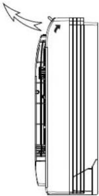

CAUTION
Do not try to adjust the horizontal louver by hand. This may cause damage the mechanism and result in condensation forming on the air outlets.
- Adjust the Air Flow Direction Left and Right
Hold the knob and move the louver.
You will find a knob on the left-side and the right-side blades.

Care and Maintenance
Cleaning Your Indoor Unit

BEFORE CLEANING OR MAINTENANCE
ALWAYS TURN OFF YOUR AIR CONDITIONER SYSTEM AND DISCONNECT ITS POWER SUPPLY BEFORE CLEANING OR MAINTENANCE.

CAUTION
Only use a soft, dry cloth to wipe the unit clean. If the unit is especially dirty, you can use a cloth soaked in warm water to wipe it clean.
- Do not use chemicals or chemically treated cloths to clean the unit
- Do not use benzene, paint thinner, polishing powder or other solvents to clean the unit. They can cause the plastic surface to crack or deform.
- Do not use water hotter than 40° C ( 104° F) to clean the front panel. This can cause the panel to deform or become discolored.
Cleaning Your Air Filter
A clogged air conditioner can reduce the cooling efficiency of your unit, and can also be bad for your health. Make sure to clean the filter once every two weeks.

WARNING: DO NOT REMOVE OR CLEAN THE FILTER BY YOURSELF
Removing and cleaning the filter can be dangerous. Removal and maintenance must be performed by a certified technician.
- Open the front panel.
- Remove the air filter.
Press the claws on the right and left sides of the air filter down slightly, then pull upward. -
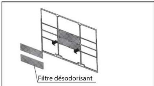
Hold the tabs of the frame, and remove the 4 claws. (The special function filter can be washed with water once every 6 months. It is recommended that you replace it once every 3 years.)
-
Clean the air filter by vacuuming the surface or washing it in warm water with mild detergent.
- Rinse the filter with clean water and allow it to air-dry. DO NOT let the filter dry in direct sunlight.
- Reinstall the filter.

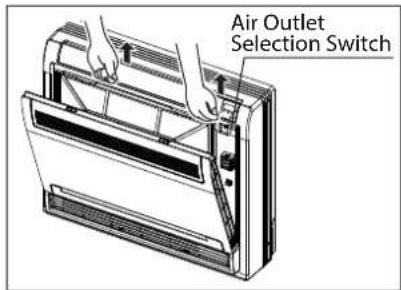

If using water, the inlet side should face down and away from the water stream.
If using a vacuum cleaner, the inlet side should face the vacuum.


CAUTION
- Before changing the filter or cleaning, turn off the unit and disconnect its power supply.
- When removing filter, do not touch metal parts in the unit. The sharp metal edges can cut you.
- Do not use water to clean the inside of the indoor unit. This can destroy insulation and cause electrical shock.
- Do not expose filter to direct sunlight when drying. This can shrink the filter.

CAUTION
- Any maintenance and cleaning of outdoor unit should be performed by an authorized dealer or a licensed service provider.
- Any unit repairs should be performed by an authorized dealer or a licensed service provider.
Maintenance – Long Periods of Non-Use
If you plan not to use your air conditioner for an extended period of time, do the following:

Clean all filters
Turn on FAN function until unit dries out completely

Turn off the unit and remove batteries disconnect the power from remote control

Maintenance – Pre-Season Inspection
After long periods of non-use, or before periods of frequent use, do the following:


Check for damaged wires Clean all filters

Check for leaks Replace batteries


Make sure nothing is blocking all air inlets and outlets
Troubleshooting

SAFETY PRECAUTIONS
If any of the following conditions occurs, turn off your unit immediately!
• The power cord is damaged or abnormally warm
• You smell a burning odor
• The unit emits loud or abnormal sounds
• A power fuse blows or the circuit breaker frequently trips
• Water or other objects fall into or out of the unit
DO NOT ATTEMPT TO FIX THESE YOURSELF! CONTACT AN AUTHORIZED SERVICE PROVIDER IMMEDIATELY!
Common Issues
The following problems are not a malfunction and in most situations will not require repairs.
| Issue Possible Causes | |
| Unit does not turn on when pressing ON/OFF button | The Unit has a 3-minute protection feature that prevents the unit from overloading. The unit cannot be restarted within three minutes of being turned off. |
| Cooling and Heating Models: If the Operation light and PRE-DEF (Pre-heating/Defrost) indicators are lit up, or the Operation light is lit up and the LCD screen display “dF”, the outdoor temperature is too cold and the unit’s anti-cold wind is activated in order to defrost the unit. | |
| The unit changes from COOL mode to FAN mode | The unit may change its setting to prevent frost from forming on the unit. Once the temperature increases, the unit will start operating in the previously selected mode again. |
| The set temperature has been reached, at which point the unit turns off the compressor. The unit will continue operating when the temperature fluctuates again. | |
| The indoor unit emits white mist | In humid regions, a large temperature difference between the room’s air and the conditioned air can cause white mist. |
| Both the indoor and outdoor units emit white mist | When the unit restarts in HEAT mode after defrosting, white mist may be emitted due to moisture generated from the defrosting process. |
| The indoor unit makes noises | A squeaking sound is heard when the system is OFF or in COOL mode. The noise is also heard when the drain pump (optional) is in operation. |
| A squeaking sound may occur after running the unit in HEAT mode due to expansion and contraction of the unit’s plastic parts. | |
| Both the indoor unit and outdoor unit make noises | Low hissing sound during operation: This is normal and is caused by refrigerant gas flowing through both indoor and outdoor units. |
| Low hissing sound when the system starts, has just stopped running, or is defrosting: This noise is normal and is caused by the refrigerant gas stopping or changing direction. | |
| Squeaking sound: Normal expansion and contraction of plastic and metal parts caused by temperature changes during operation can cause squeaking noises. | |
| The outdoor unit makes noises | The unit will make different sounds based on its current operating mode. |
| Dust is emitted from either the indoor or outdoor unit | The unit may accumulate dust during extended periods of non-use, which will be emitted when the unit is turned on. This can be mitigated by covering the unit during long periods of inactivity. |
| The unit emits a bad odor | The unit may absorb odors from the environment (such as furniture, cooking, cigarettes, etc.) which will be emitted during operations. |
| The unit's filters have become moldy and should be cleaned. | |
| The fan of the outdoor unit does not operate | During operation, the fan speed is controlled to optimize product operation. |
NOTE: If problem persists, contact a local dealer or your nearest customer service center. Provide them with a detailed description of the unit malfunction as well as your model number.
Troubleshooting
When troubles occur, please check the following points before contacting a repair company.
| Problem Possible Causes Solution | ||
| Poor Cooling Performance | Temperature setting may be higher than ambient room temperature | Lower the temperature setting |
| The heat exchanger on the indoor or outdoor unit is dirty | Clean the affected heat exchanger | |
| The air filter is dirty | Remove the filter and clean it according to instructions | |
| The air inlet or outlet of either unit is blocked | Turn the unit off, remove the obstruction and turn it back on | |
| Doors and windows are open | Make sure that all doors and windows are closed while operating the unit | |
| Excessive heat is generated by sunlight | Close windows and curtains during periods of high heat or bright sunshine | |
| Too many sources of heat in the room (people, computers, electronics, etc.) | Reduce amount of heat sources | |
| Low refrigerant due to leak or long-term use | Check for leaks, re-seal if necessary and top off refrigerant | |
| The unit is not working | Power failure | Wait for the power to be restored |
| The power is turned off Turn on the power | ||
| The fuse is burned out | Replace the fuse | |
| Remote control batteries are dead | Replace batteries | |
| The Unit's 3-minute protection has been activated | Wait three minutes after restarting the unit | |
| Timer is activated | Turn timer off | |
| The unit starts and stops frequently | There's too much or too little refrigerant in the system | Check for leaks and recharge the system with refrigerant. |
| Incompressible gas or moisture has entered the system. | Evacuate and recharge the system with refrigerant | |
| System circuit is blocked | Determine which circuit is blocked and replace the malfunctioning piece of equipment | |
| The compressor is broken Replace the compressor | ||
| The voltage is too high or too low | Install a manostat to regulate the voltage | |
| Poor heating performance | The outdoor temperature is extremely low | Use auxiliary heating device |
| Cold air is entering through doors and windows | Make sure that all doors and windows are closed during use | |
| Low refrigerant due to leak or long-term use | Check for leaks, re-seal if necessary and top off refrigerant | |
| Indicator lamps continue flashing | The unit may stop operation or continue to run safely. If the indicator lamps continue to flash or error codes appear, wait for about 10 minutes. The problem may resolve itself.If not, disconnect the power, then connect it again. Turn the unit on.If the problem persists, disconnect the power and contact your nearest customer service center. | |
| Error code appears and begins with the letters as the following in the window display of indoor unit:• E(x), P(x), F(x)• EH(xx), EL(xx), EC(xx)• PH(xx), PL(xx), PC(xx) | ||
NOTE: If your problem persists after performing the checks and diagnostics above, turn off your unit immediately and contact an authorized service center.
Accessories
The air conditioning system comes with the following accessories. Use all of the installation parts and accessories to install the air conditioner. Improper installation may result in water leakage, electrical shock and fire, or cause the equipment to fail. The items are not included with the air conditioner must be purchased separately.
| Name of Accessories | Q'ty(pc) | Shape | Name of Accessories | Q'ty(pc) | Shape |
| Manual | 2~4 |  | Soundproof / insulation sheath (some models) | 2 |  |
| Transfer connector (ΦΦ 12.7-ΦΦ 15.9) (some models) | 1 | 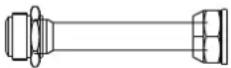 | Mounting plate | 1 | 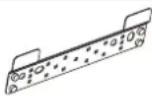 |
| Transfer connector (ΦΦ 6.35-ΦΦ 9.52) (some models) | 1 | 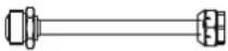 | Anchor | 6 (depending on models) |  |
| Transfer connector (ΦΦ 9.52-ΦΦ 12.7) (some models) | 1 | 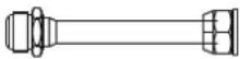 | Mounting plate fixing screw | 6 (depending on models) |  |
| Magnetic ring (wrap the electric wires S1 & S2 (P & Q & E) around the magnetic ring twice) (some models) | 1 |  | Drain joint (some models) | 1 |  |
| Seal ring (some models) | 1 |  | |||
| Magnetic ring (Hitch it on the connective cable between indoor unit and outdoor unit after installation.) (some models) | 1 |  | Copper nut | 2 |  |
| Red short connected wire (some models) | 1 | _ |
Optional accessories
• There are two types of remote controls: wired and wireless.
Select a remote controller based on customer preferences and requirements and install in an appropriate place.
Refer to catalogues and technical literature for guidance on selecting a suitable remote controller.
| Name | Shape Quantity(PC) | ||
| Connecting pipe assembly | Liquid side | Φ6.35(1/4 in) | Parts you must purc hase separately. Consult the dealer about the proper pipe size of the unit you purchased. |
| Φ9.52(3/8in) | |||
| Φ12.7(1/2in) | |||
| Gas side | Φ9.52(3/8in) | ||
| Φ12.7(1/2in) | |||
| Φ16(5/8in) | |||
| Φ19(3/4in) | |||
| Φ22(7/8in) | |||
Installation Summary
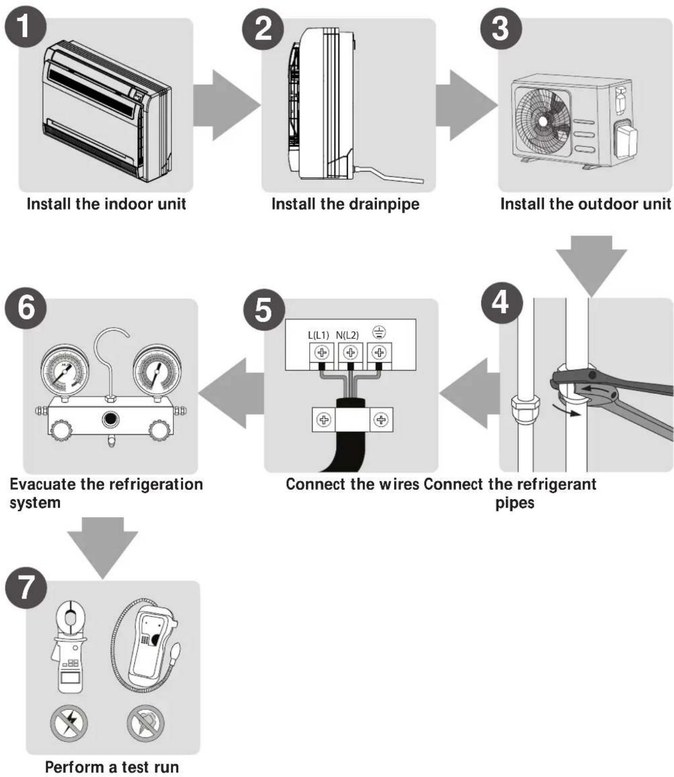
Unit Parts
NOTE: The installation must be performed in accordance with the requirement of local and national standards. The installation may be slightly different in different areas.
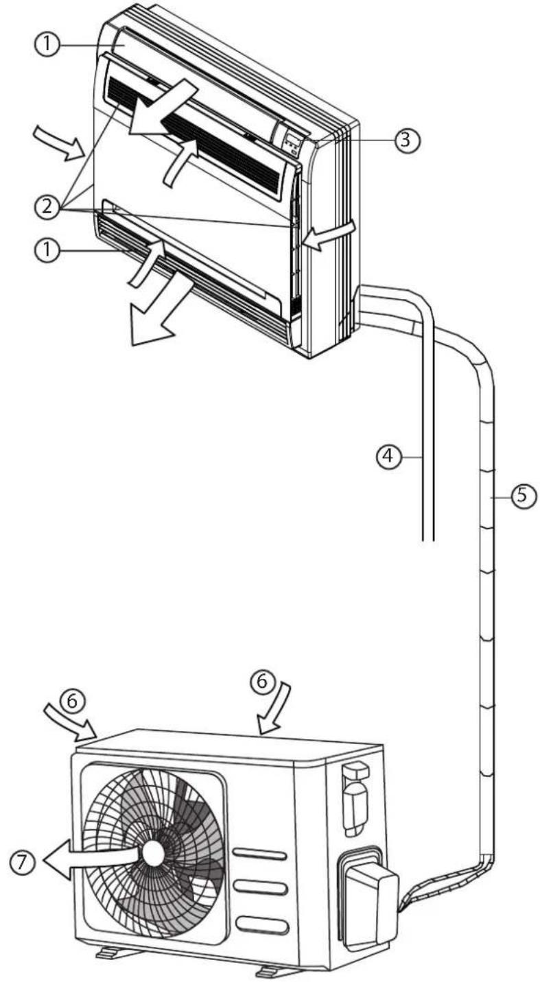
① Air flow louver (at air outlet)
② Air inlet (with air filter in it)
③ Display panel
④ Drain pipe
⑤ Connecting pipe
⑥ Air inlet
⑦ Air outlet
NOTE ON ILLUSTRATIONS
Illustrations in this manual are for explanatory purposes. The actual shape of your indoor unit may be slightly different. The actual shape shall prevail.
Indoor Unit Installation
Installation Instructions – Indoor unit
NOTE: Panel installation should be performed after piping and wiring have been completed.
Step 1: Select installation location
Before installing the indoor unit, you must choose an appropriate location. The following are standards that will help you choose an appropriate location for the unit.
Proper installation locations meet the following standards:
√ Enough room exists for installation and maintenance.
√ Enough room exists for the connecting the pipe and drainpipe.
☑ The ceiling is horizontal and its structure can sustain the weight of the indoor unit.
√ The air inlet and outlet are not blocked.
√ The airflow can fill the entire room.
√ There is no direct radiation from heaters.
DO NOT install unit in the following locations:
∅ Areas with oil drilling or fracking
∅ Coastal areas with high salt content in the air
Areas with caustic gases in the air, such as hot springs
∅ Areas that experience power fluctuations, such as factories
∅ Enclosed spaces, such as cabinets
∅ Kitchens that use natural gas
∅ Areas with strong electromagnetic waves
∅ Areas that store flammable materials or gas
∅ Rooms with high humidity, such as bathrooms or laundry rooms
Recommended distances between the indoor unit
The distance between the mounted indoor unit should meet the specifications illustrated in the following diagram.


Step 2: Installing the main body
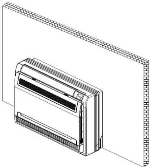
• Fix the mounting plate with a tapping screw onto the wall.

- Hang the indoor unit on the mounting plate.
(The bottom of body can touch the floor or remain suspended, but the body must be installed vertically.)
Step 3: Taking the indoor unit apart to connect the pipes
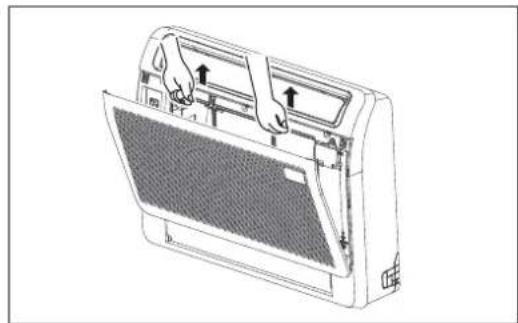
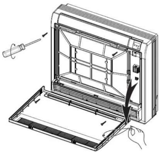
1. Open the front panel
Slide the two stoppers on the left and right sides inward until they click.

3. Remove the face plate.
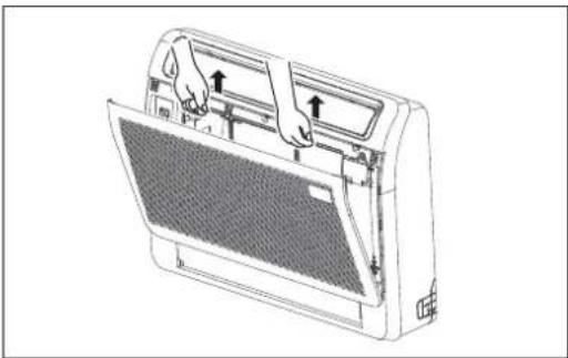
Remove the four screws. Open the bottom of the face plate at a 30-degree angle. Lift the top of the face plate.

NOTE: All the figures in this manual are for demonstration purposes only. The air conditioner you have purchased may be slightly different in design, though similar in shape.
2. Remove the front panel.
Remove the string.
Allow the front panel to fall forward and remove it.
Step 4: Network address set (some models)
(Only unit of 18000Btu/h has the function that Network address set.)
Every air-conditioner in network has only one network address to distinguish each other.
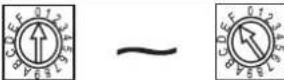
Address code of air-conditioner in LAN is set by code switches S1 & S2 on the Main Control Board of the indoor unit, and the set range is 0-63.
| Toggle switch set | Network address code | |
| S1 | S2 | |
 | 00~15 | |
 | 16~31 | |
 | 32~47 | |
 | 48-63 | |
Step 5: Drill wall hole for connective piping
- Determine the location of the wall hole based on the location of the outdoor unit.
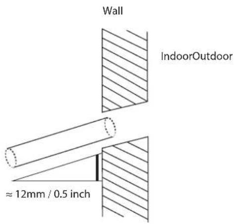
- Using a 65mm (2.5in) or 90mm(3.54in) (depending on models) core drill, drill a hole in the wall. Make sure that the hole is drilled at a slight downward angle, so that the outdoor end of the hole is lower than the indoor end by about 12mm (0.5in). This will ensure proper water drainage.
- Place the protective wall cuff in the hole. This protects the edges of the hole and will help seal it when you finish the installation process.

CAUTION
When drilling the wall hole, make sure to avoid wires, plumbing, and other sensitive
Step 6: Connect drain hose
The drainpipe is used to drain water away from the unit. Improper installation may cause unit and property damage.

CAUTION
• Insulate all piping to prevent condensation, which could lead to water damage.
- If the drainpipe is bent or installed incorrectly, water may leak and cause a water-level switch malfunction.
- In HEAT mode, the outdoor unit will discharge water. Ensure that the drain hose is placed in an appropriate area to avoid water damage and slippage.
- DO NOT pull the drainpipe forcefully. This could disconnect it.
NOTE ON PURCHASING PIPES
Installation requires a polyethylene tube (exterior diameter = 3.7-3.9cm, interior diameter = 3.2cm), which can be obtained at your localhardware store or dealer.
- Cover the drainpipe with heat insulation to prevent condensation and leakage.
- Attach the mouth of the drain hose to the unit's outlet pipe. Sheath the mouth of the hose and clip it firmly with a pipe clasp.
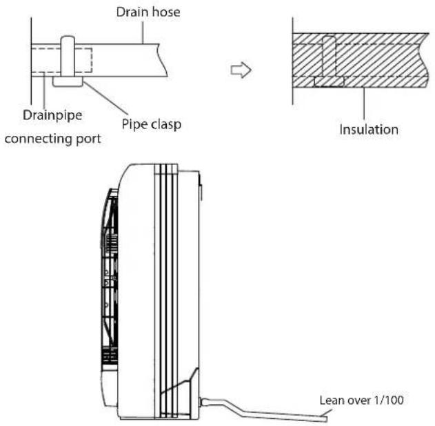
NOTE ON DRAINPIPE INSTALLATION
- When using an extended drainpipe, tighten the indoor connection with an additional protection tube. This prevents it from pulling loose.
- The drainpipe should slope downward at a gradient of at least 1/100 to prevent water from flowing back into the air conditioner.
- Incorrect installation could cause water to flow back into the unit and flood.
NOTE: When connecting multiple drainpipes, install the pipes as illustrated.

Outdoor Unit Installation
Install the unit by following local codes and regulations, there may be differ slightly between different regions.

Installation Instructions – Outdoor unit
Step 1: Select installation location
Before installing the outdoor unit, you must choose an appropriate location. The following are standards that will help you choose an appropriate location for the unit.
Proper installation locations meet the following standards:
√ Meets all spatial requirements shown in Installation Space Requirements above.
√ Good air circulation and ventilation
√ Firm and solid—the location can support the unit and will not vibrate
√ Noise from the unit will not disturb others
√ Protected from prolonged periods of direct sunlight or rain
√ Where snowfall is anticipated, raise the unit above the base pad to prevent ice buildup and coil damage. Mount the unit high enough to be above the average accumulated area snowfall. The minimum height must be 18 inches
DO NOT install unit in the following locations:
∅ Near an obstacle that will block air inlets and outlets
Near a public street, crowded areas, or where noise from the unit will disturb others
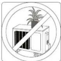
Near animals or plants that will be harmed by hot air discharge
⊗ Near any source of combustible gas
∅ In a location that is exposed to large amounts of dust
∅ In a location exposed to a excessive amounts of salty air
If the unit is exposed to heavy wind:
Install unit so that air outlet fan is at a 90° angle to the direction of the wind. If needed, build a barrier in front of the unit to protect it from extremely heavy winds.
See Figures below.

If the unit is frequently exposed to heavy rain or snow:
Build a shelter above the unit to protect it from the rain or snow. Be careful not to obstruct air flow around the unit.
If the unit is frequently exposed to salty air (seaside):
Use outdoor unit that is specially designed to resist corrosion.
Step 2: Install drain joint(Heat pump unit only)
Before bolting the outdoor unit in place, you must install the drain joint at the bottom of the unit. Note that there are two different types of drain joints depending on the type of outdoor unit.
If the drain joint comes with a rubber seal (see Fig. A), do the following:
- Fit the rubber seal on the end of the drain joint that will connect to the outdoor unit.
- Insert the drain joint into the hole in the base pan of the unit.
- Rotate the drain joint 90° until it clicks in place facing the front of the unit.
- Connect a drain hose extension (not included) to the drain joint to redirect water from the unit during heating mode.
If the drain joint doesn't come with a rubber seal (see Fig. B), do the following:
- Insert the drain joint into the hole in the base pan of the unit. The drain joint will click in place.
- Connect a drain hose extension (not included) to the drain joint to redirect water from the unit during heating mode.

(A) (B)

IN COLD CLIMATES
In cold climates, make sure that the drain hose is as vertical as possible to ensure swift water drainage. If water drains too slowly, it can freeze in the hose and flood the unit.
Step 3: Anchor outdoor unit
The outdoor unit can be anchored to the ground or to a wall-mounted bracket with bolt(M10). Prepare the installation base of the unit according to the dimensions below.
UNIT MOUNTING DIMENSIONS
The following is a list of different outdoor unit sizes and the distance between their mounting feet. Prepare the installation base of the unit according to the dimensions below.
Outdoor Unit Types and Specifications
Split Type Outdoor Unit

(unit: mm/inch)
| Outdoor Unit DimensionsW x H x D | Mounting Dimensions | |
| Distance A | Distance B | |
| 760x590x285 (29.9x23.2x11.2) 530 (20.85) 290 (11.4) | ||
| 780x540x250 (30.7x21.25x9.85) 549 (21.6) 276 (10.85) | ||
| 770x555x300 (30.3x21.85x11.8) 487 (19.2) 298 (11.7) | ||
| 810x558x310 (31.9x22x12.2) 549 (21.6) 325 (12.8) | ||
| 845x700x320 (33.27x27.5x12.6) 560 (22) 335 (13.2) | ||
| 900x860x315 (35.4x33.85x12.4) 590 (23.2) 333 (13.1) | ||
| 945x810x395 (37.2x31.9x15.55) 640 (25.2) 405 (15.95) | ||
| 990x965x345 (38.98x38x13.58) 624 (24.58) 366 (14.4) | ||
| 938x1369x392 (36.93x53.9x15.43) 634 (24.96) 404 (15.9) | ||
| 900x1170x350 (35.4x46x13.8) 590 (23.2) 378 (14.88) | ||
| 800x554x333 (31.5x21.8x13.1) 514 (20.24) 340 (13.39) | ||
| 845x702x363 (33.27x27.6x14.3) | 540 (21.26) | 350 (13.8) |
| 946x810x420 (37.24x31.9x16.53) 673 (26.5) | 403 (15.87) | |
| 946x810x410 (37.24x31.9x16.14) 673 (26.5) | 403 (15.87) | |
| 952x1333x410 (37.5x52.5x16.14) 634 (24.96) | 404 (15.9) | |
| 952x1333x415 (37.5x52.5x16.34) 634 (24.96) | 404 (15.9) | |
| 890x673x342 (35x26.5x13.46) 663 (26.1) | 354 (13.94) | |
Rows of series installation
The relations between H, A and L are as follows.
| L | A | |
| L ≤ H | L ≤ 1/2H | 25 cm / 9.8" or more |
| 1/2H < L ≤ H | 30 cm / 11.8" or more | |
| L > H | Can not be installed | |

Refrigerant Piping Connection
When connecting refrigerant piping, do not let substances or gases other than the specified refrigerant enter the unit. The presence of other gases or substances will lower the unit's capacity, and can cause abnormally high pressure in the refrigeration cycle. This can cause explosion and injury.
Note on Pipe Length
Ensure that the length of the refrigerant pipe, the number of bends, and the drop height between the indoor and outdoor units meets the requirements shown in the following table:
The Maximum Length And Drop Height Based on Models. (Unit: m/ft.)
| Type of model Capacity (Btu/h) Length of piping Maximum drop height | |||
| North America, Australia and the eu frequency conversion Split Type | <15K 25/82 10/32.8 | ||
| ≥15K - <24K 30/984 20/65.6 | |||
| ≥24K - <36K 50/164 25/82 | |||
| ≥36K - ≤60K 65/213 30/98.4 | |||
| Other Split Type | 12K 15/49 | 8/26 | |
| 18K-24K | 25/82 | 15/49 | |
| 30K-36K | 30/98.4 20/65.6 | ||
| 42K-60K | 50/164 | 30/98.4 | |

CAUTION
Mark the data plate with the Orifice installed(for some models).
- Please purchase the fittings according to the requirements in the manual strictly.
• Refer the diagram when installing.

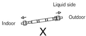


CAUTION
Oil traps
If oil flows back into the outdoor unit's compressor, this might cause liquid compression or deterioration of oil return. Oil traps in the rising gas piping can prevent this.
An oil trap should be installed every 6m(20ft) of vertical suction line riser (<36000Btu/h unit).
An oil trap should be installed every 10m(32.8ft) of vertical suction line riser ( ≥ 36000Btu/h unit).

Connection Instructions – Refrigerant Piping

CAUTION
- The branching pipe must be installed horizontally. An angle of more than 10° may cause malfunction.
- DO NOT install the connecting pipe until both indoor and outdoor units have been installed.
• Insulate both the gas and liquid piping to prevent water leakage.
Step 1: Cut pipes
When preparing refrigerant pipes, take extra care to cut and flare them properly. This will ensure efficient operation and minimize the need for future maintenance.
- Measure the distance between the indoor and outdoor units.
- Using a pipe cutter, cut the pipe a little longer than the measured distance.
- Make sure that the pipe is cut at a perfect 90° angle.


DO NOT DEFORM PIPE WHILE CUTTING
Be extra careful not to damage, dent, or deform the pipe while cutting. This will drastically reduce the heating efficiency of the unit.
Step 2: Remove burrs.
Burrs can affect the air-tight seal of refrigerant piping connection. They must be completely removed.
-
Hold the pipe at a downward angle to prevent burrs from falling into the pipe.
-
Using a reamer or deburring tool, remove all burrs from the cut section of the pipe.

Step 3: Flare pipe ends
Proper flaring is essential to achieve an airtight seal.
- After removing burrs from cut pipe, seal the ends with PVC tape to prevent foreign materials from entering the pipe.
- Sheath the pipe with insulating material.
- Place flare nuts on both ends of pipe. Make sure they are facing in the right direction, because you can't put them on or change their direction after flaring.

- Remove PVC tape from ends of pipe when ready to perform flaring work.
- Clamp flare form on the end of the pipe. The end of the pipe must extend beyond the flare form.
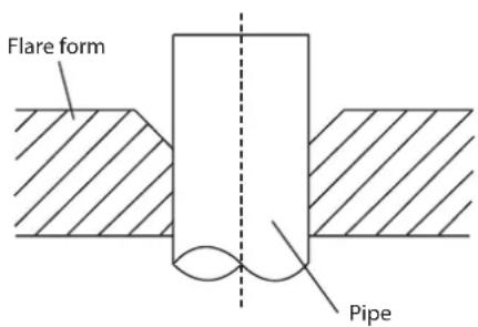
- Place flaring tool onto the form.
- Turn the handle of the flaring tool clockwise until the pipe is fully flared. Flare the pipe in accordance with the dimensions.
PIPING EXTENSION BEYOND FLARE FORM
| Pipe gauge | Tightening torque | Flare dimension (A) (Unit: mm/Inch) | Flare shape | |
| Min. Max. | ||||
| ∅ 6.35 | 18-20 N.m (183-204 kgf.cm) | 8.4/0.33 | 8.7/0.34 | 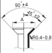 |
| ∅ 9.52 | 25-26 N.m (255-265 kgf.cm) | 13.2/0.52 | 13.5/0.53 | |
| ∅ 12.7 | 35-36 N.m (357-367 kgf.cm) | 16.2/0.64 | 16.5/0.65 | |
| ∅ 16 | 45-47 N.m (459-480 kgf.cm) | 19.2/0.76 | 19.7/0.78 | |
| ∅ 19 | 65-67 N.m (663-683 kgf.cm) | 23.2/0.91 | 23.7/0.93 | |
| ∅ 22 | 75-85N.m (765-867 kgf.cm) | 26.4/1.04 | 26.9/1.06 | |
- Remove the flaring tool and flare form, then inspect the end of the pipe for cracks and even flaring.
Step 4: Connect pipes
Connect the copper pipes to the indoor unit first, then connect it to the outdoor unit. You should first connect the low-pressure pipe, then the high-pressure pipe.
- When connecting the flare nuts, apply a thin coat of refrigeration oil to the flared ends of the pipes.
- Align the center of the two pipes that you will connect.

- Tighten the flare nut as tightly as possible by hand.
-
Using a spanner, grip the nut on the unit tubing.
-
While firmly gripping the nut, use a torque wrench to tighten the flare nut according to the torque values in above table.
NOTE: Use both a spanner and a torque wrench when connecting or disconnecting pipes to/from the unit.


CAUTION
- Ensure to wrap insulation around the piping. Direct contact with the bare piping may result in burns or frostbite.
- Make sure the pipe is properly connected. Over tightening may damage the bell mouth and under tightening may lead to leakage.
NOTE ON MINIMUM BEND RADIUS
Carefully bend the tubing in the middle according to the diagram below. DO NOT bend the tubing more than 90° or more than 3 times.
Bend the pipe with thumb

min-radius 10cm (3.9")
- After connecting the copper pipes to the indoor unit, wrap the power cable, signal cable and the piping together with binding tape.
NOTE: DO NOT intertwine signal cable with other wires. While bundling these items together, do not intertwine or cross the signal cable with any other wiring.
- Thread this pipeline through the wall and connect it to the outdoor unit.
- Insulate all the piping, including the valves of the outdoor unit.
- Open the stop valves of the outdoor unit to start the flow of the refrigerant between the indoor and outdoor unit.

CAUTION
Check to make sure there is no refrigerant leak after completing the installation work. If there is a refrigerant leak, ventilate the area immediately and evacuate the system (refer to the Air Evacuation section of this manual).
Wiring
BEFORE PERFORMING ANY ELECTRICAL WORK, READ THESE REGULATIONS
- All wiring must comply with local and national electrical codes, regulations and must be installed by a licensed electrician.
- All electrical connections must be made according to the Electrical Connection Diagram located on the panels of the indoor and outdoor units.
- If there is a serious safety issue with the power supply, stop work immediately. Explain your reasoning to the client, and refuse to install the unit until the safety issue is properly resolved.
- Power voltage should be within 90-110% of rated voltage. Insufficient power supply can cause malfunction, electrical shock, or fire.
- If connecting power to fixed wiring, a surgeprotector and main power switch should be installed.
- If connecting power to fixed wiring, a switch or circuit breaker that disconnects all poles and has a contact separation of at least 1/8in (3mm) must be incorporated in the fixed wiring. The qualified technician must use an approved circuit breaker or switch.
- Only connect the unit to an individual branch circuit outlet. Do not connect another appliance to that outlet.
- Make sure to properly ground the air conditioner.
- Every wire must be firmly connected. Loose wiring can cause the terminal to overheat, resulting in product malfunction and possible fire.
- Do not let wires touch or rest against refrigerant tubing, the compressor, or any moving parts within the unit.
- If the unit has an auxiliary electric heater, it must be installed at least 1 meter (40in) away from any combustible materials.
-
To avoid getting an electric shock, never touch the electrical components soon after the power supply has been turned off. After turning off the power, always wait 10 minutes or more before you touch the electrical components.
-
Make sure that you do not cross your electrical wiring with your signal wiring. This may cause distortion and interference.
- The unit must be connected to the main outlet. Normally, the power supply must have a impedance of 32 ohms.
- No other equipment should be connected to the same power circuit.
- Connect the outdoor wires before connecting the indoor wires.
WARNING
BEFORE PERFORMING ANY ELECTRICAL OR WIRING WORK, TURN OFF THE MAIN POWER TO THE SYSTEM.
NOTE ON AIR SWITCH
When the maximum current of the air conditioner is more than 16A, an air switch or leakage protection switch with protective device shall be used (purchased separately). When the maximum current of the air conditioner is less than 16A, the power cord of air conditioner shall be equipped with plug (purchased separately). In North America, the appliance should be wired according to NEC and CEC requirements.
![graph TD A["Indoor unit"] --> B["Outdoor unit"] B --> C["Air switch (purchased separately)"] B --> D["Outdoor unit power wires"] D --> E["Indoor & Outdoor connective wires (purchased separately)"] B --> F["Ground"]](/content/2026/07/1457576/images/fbcf5aaa62ae9719885d7e663bb460b36b220cd3643843f6a286a7d2b2dba505.jpg)
(B)
![graph TD A["Indoor unit"] --> B["Outdoor unit"] B --> C["Indoor unit power wires"] C --> D["Air switch (purchased separately)"] D --> E["Indoor unit"] E --> F["Indoor & Outdoor connective wires (purchased separately)"] F --> G["Ground"]](/content/2026/07/1457576/images/3ab5d9f4794e8b33eb912b74306a20f54cb765c07624a187079b450ce32956ef.jpg)
(C)
![graph TD A["Indoor unit"] -->|purchased separately| B["Outdoor unit"] A -->|purchased separately| C["Air switch"] A -->|purchased separately| D["Indoor unit"] A -->|purchased separately| E["Outdoor unit"] F["Indoor & Outdoor connective wires (purchased separately)"] --> A G["Outdoor unit power wires…](/content/2026/07/1457576/images/1bb0eaa3e26871222f6bb2ed9c979f294e5b0887b456d798e7c09ddb006c454f.jpg)
(D) (Only for the North American)
![graph TD A["Air switch (purchased separately)"] --> B["Outdoor unit power wires"] B --> C["Outdoor unit"] C --> D["Indoor unit"] D --> E["Indoor & Outdoor connective wires (purchased separately)"] C --> F["Air switch (purchased separately)"] F --> G["Ground"]](/content/2026/07/1457576/images/990e8a38d22ed30fb651f315411f45923f3fb822d84417c238fc3d64ed06971a.jpg)
NOTE: The cographs are for explanation purpose only. Your machine may be slightly different. The actual shape shall prevail.
Outdoor Unit Wiring

WARNING
Before performing any electrical or wiring work, turn off the main power to the system.
- Prepare the cable for connection a. You must first choose the right cable size. Be sure to use H07RN-F cables.
NOTE: In North America, choose the cable type according to the local electrical codes and regulations.
Minimum Cross-Sectional Area of Power and Signal Cables (For reference)
| Rated Current of Appliance (A) | Nominal Cross-Sectional Area ( mm2 ) |
| >3 and ≤6 | 0.75 |
| >6 and ≤10 | 1 |
| >10 and ≤16 | 1.5 |
| >16 and ≤25 | 2.5 |
| >25 and ≤32 | 4 |
| >32 and ≤40 | 6 |
CHOOSE THE RIGHT CABLE SIZE
The size of the power supply cable, signal cable, fuse, and switch needed is determined by the maximum current of the unit. The maximum current is indicated on the nameplate located on the side panel of the unit. Refer to this nameplate to choose the right cable, fuse, or switch.
NOTE: In North America, please choose the right cable size according to the Minimum Circuit Ampacity indicated on the nameplate of the unit.
b. Using wire strippers, strip the rubber jacket from both ends of the signal cable to reveal approximately 15cm (5.9") of wire.
c. Strip the insulation from the ends.
d. Using a wire crimper, crimp u-lugs on the ends.
NOTE: When connecting the wires, strictly follow the wiring diagram found inside the electrical box cover.
- Remove the electric cover of the outdoor unit. If there is no cover on the outdoor unit, take off the bolts from the maintenance board and remove the protection board.
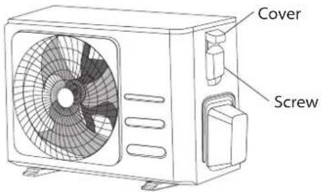
- Connect the u-lugs to the terminals Match the wire colors/labels with the labels on the terminal block. Firmly screw the u-lug of each wire to its corresponding terminal.
- Clamp down the cable with the cable clamp.
- Insulate unused wires with electrical tape. Keep them away from any electrical or metal parts.
- Reinstall the cover of the electric control box.
Indoor Unit Wiring
- Prepare the cable for connection
a. Using wire strippers, strip the rubber jacket from both ends of the signal cable to reveal about 15cm (5.9") of the wire.
b. Strip the insulation from the ends of the wires.
c. Using a wire crimper, crimp the u-lugs to the ends of the wires.
-
Rotate the sensor device's installation bearer to the other side. Then remove the cover of the electrical box. (Also, remove the electrical box also if its capacity is 18000btu/h and has networking functionality.)
-
Connect the u-lugs to the terminals.
Match the wire colors/labels with the labels on the terminal block, Firmly screw the u-lug of each wire to its corresponding terminal. Refer to the Serial Number and Wiring Diagram located on the cover of the electric control box.

Magnetic ring(if supplied and packed with the accessories) 1 2 3

CAUTION
- While connecting the wires, please strictly follow the wiring diagram.
-
The refrigerant circuit can become very hot. Keep the interconnection cable away from the copper tube.
-
Clamp down cable with the designated cable clamp to secure it in place. The cable should not be loose, and should not pull on the u-lugs.
- Reinstall the electric box cover and the front panel of the indoor unit.
Power Specifications(Not applicable for North America)
| MODEL(Btu/h) | <16K | 16K~18K | |
| POWER | PHASE | 1 Phase | 1 Phase |
| FREQUENCY AND VOLT | 220-240V~, 50Hz/60Hz | 220-240V~, 50Hz/60Hz | |
| CIRCUIT BREAKER/FUSE(A) | 20/16 | 20/16 | |
| INDOOR UNIT POWER WIRING( mm2 ) | —— | 3x1.0 | |
| INDOOR/OUDOOR CONNECTING WIRING( mm2 ) | OUTDOOR UNIT POWER WIRING | 3x1.5 | 3x2.5 |
| STRONG ELECTRIC SIGNAL | 4x1.0 | —— | |
| WEAK ELECTRIC SIGNAL | —— | 3x0.2 | |
| GROUND WIRING | 1.5 | 2.5 | |
Air Evacuation
Preparations and Precautions
Air and foreign matter in the refrigerant circuit can cause abnormal rises in pressure, which can damage the air conditioner, reduce its efficiency, and cause injury. Use a vacuum pump and manifold gauge to evacuate the refrigerant circuit, removing any non-condensable gas and moisture from the system.
Evacuation should be performed upon initial installation and when unit is relocated.
BEFORE PERFORMING EVACUATION
☑ Check to make sure the connective pipes between the indoor and outdoor units are connected properly.
√ Check to make sure all wiring is connected properly.
Evacuation Instructions
- Connect the charge hose of the manifold gauge to service port on the outdoor unit's low pressure valve.
- Connect another charge hose from the manifold gauge to the vacuum pump.
- Open the Low Pressure side of the manifold gauge. Keep the High Pressure side closed.
- Turn on the vacuum pump to evacuate the system.
- Run the vacuum for at least 15 minutes, or until the Compound Meter reads -76cmHG (-10Pa).

- Close the Low Pressure side of the manifold gauge, and turn off the vacuum pump.
-
Wait for 5 minutes, then check that there has been no change in system pressure.
-
If there is a change in system pressure, refer to Gas Leak Check section for information on how to check for leaks. If there is no change in system pressure, unscrew the cap
- from the packed valve (high pressure valve). Insert hexagonal wrench into the packed valve (high pressure valve) and open the valve by turning the wrench in a 1/4 counterclockwise turn. Listen for gas to exit the system, then close the valve after 5 seconds.
- Watch the Pressure Gauge for one minute to make sure that there is no change in pressure. The Pressure Gauge should read slightly higher than atmospheric pressure.
- Remove the charge hose from the service port.

- Using hexagonal wrench, fully open both the high pressure and low pressure valves.
- Tighten valve caps on all three valves (service port, high pressure, low pressure) by hand. You may tighten it further using a torque wrench if needed.
OPEN VALVE STEMS GENTLY
When opening valve stems, turn the hexagonal wrench until it hits against the stopper. Do not try to force the valve to open further.
Note on Adding Refrigerant
Some systems require additional charging depending on pipe lengths. The standard pipe length varies according to local regulations. For example, in North America, the standard pipe length is 7.5m (25'). In other areas, the standard pipe length is 5m (16'). The refrigerant should be charged from the service port on the outdoor unit's low pressure valve. The additional refrigerant to be charged can be calculated using the following formula:
Liquid Side Diameter
| φ 6.35(1/4") φ 9.52(3/8") φ 12.7(1/2") | |||
| R22(orifice tube in the indoor unit): | (Total pipe length - standard pipe length)x 30g (0.32oZ)/m(ft) | (Total pipe length - standard pipe length)x 65g(0.69oZ)/m(ft) | (Total pipe length - standard pipe length)x 115g(1.23oZ)/m(ft) |
| R22(orifice tube in the outdoor unit): | (Total pipe length - standard pipe length)x15g(0.16oZ)/m(ft) | (Total pipe length - standard pipe length)x30(0.32oZ)/m(ft) | (Total pipe length - standard pipe length)x60g(0.64oZ)/m(ft) |
| R410A:(orifice tube in the indoor unit): | (Total pipe length - standard pipe length)x30g(0.32oZ)/m(ft) | (Total pipe length - standard pipe length)x65g(0.69oZ)/m(ft) | (Total pipe length - standard pipe length)x115g(1.23oZ)/m(ft) |
| R410A:(orifice tube in the outdoor unit): | (Total pipe length - standard pipe length)x15g(0.16oZ)/m(ft) | (Total pipe length - standard pipe length)x30g(0.32oZ)/m(ft) | (Total pipe length - standard pipe length)x65g(0.69oZ)/m(ft) |
| R32 : | (Total pipe length - standard pipe length)x 12g(0.13oZ)/m(ft) | (Total pipe length - standard pipe length)x 24g(0.26oZ)/m(ft) | (Total pipe length - standard pipe length)x 40g(0.42oZ)/m(ft) |

CAUTION DO NOT mix refrigerant types.
Only for Australia models :
- This unit contains factory charged refrigerant covering 20m of refrigerant piping and additional refrigerant charge on the installation site is not required for an installation with up to 20m refrigerant piping. When refrigerant piping exceeds 20m, additionally charge an amount calculated from the pipe length and the above table for the portion in excess of 20m.
- If an existing pipe system is used, a required refrigerant charge volume will vary depending on the liquid pipe size.
Formula to calculate the volume of additional refrigerant required:
Additional charge volume (kg) = { Main length (m) - Factory charged volume 20(m) } × 0.03(kg/m) - Make sure to remove the additional refrigerant amount according to the nameplate rated charge (under 5m refrigerant piping) under market or government verification testing.
Test Run
Before Test Run
A test run must be performed after the entire system has been completely installed. Confirm the following points before performing the test:
a) Indoor and outdoor units are properly installed.
b) Piping and wiring are properly connected.
c) No obstacles near the inlet and outlet of the unit that might cause poor performance or product malfunction.
d) Refrigeration system does not leak.
e) Drainage system is unimpeded and draining to a safe location.
f) Heating insulation is properly installed.
g) Grounding wires are properly connected.
h) Length of the piping and additional refrigerant stow capacity have been recorded.
i) Power voltage is the correct voltage for the air conditioner.

CAUTION
Failure to perform the test run may result in unit damage, property damage, or personal injury.
Test Run Instructions
- Open both the liquid and gas stop valves.
- Turn on the main power switch and allow the unit to warm up.
- Set the air conditioner to COOL mode.
- For the Indoor Unit
a. Ensure the remote control and its buttons work properly.
b. Ensure the louvers move properly and can be changed using the remote control.
c. Double check to see if the room temperature is being registered correctly.
d. Ensure the indicators on the remote control and the display panel on the indoor unit work properly.
e. Ensure the manual buttons on the indoor unit works properly.
f. Check to see that the drainage system is unimpeded and draining smoothly.
g. Ensure there is no vibration or abnormal noise during operation.
- For the Outdoor Unit
a. Check to see if the refrigeration system is leaking.
b. Make sure there is no vibration or abnormal noise during operation.
c. Ensure the wind, noise, and water generated by the unit do not disturb your neighbors or pose a safety hazard.
- Drainage Test
a. Ensure the drainpipe flows smoothly. New buildings should perform this test before finishing the ceiling.
b. Remove the test cover. Add 2,000ml of water to the tank through the attached tube.
c. Turn on the main power switch and run the air conditioner in COOL mode.
d. Listen to the sound of the drain pump to see if it makes any unusual noises.
e. Check to see that the water is discharged. It may take up to one minute before the unit begins to drain depending on the drainpipe.
f. Make sure that there are no leaks in any of the piping.
g. Stop the air conditioner. Turn off the main power switch and reinstall the test cover.
NOTE: If the unit malfunctions or does not operate according to your expectations, please refer to the Troubleshooting section of the Owner's Manual before calling customer service.
FRANÇAIS
MANUEL DE L'UTILISATEUR ET D'INSTALLATION
CONSOLE MULTISPLIT
ADMIRA
HTW-MFI-035ADMR32 | HTW-MFI-046ADMR32
Table des Matières
! MISE EN GARDE

Vérifier les fuites

Remplacer les piles


Tuyau de vidange Cordon d'alimentation
- Retirez la plaque de recouvrement.
(unité : mm/pouce)
| Dimensions de l'unité extérieureAn x Al x Pr | Cotes de montage | |
| Distance A | Distance B | |
| 760x590x285 (29.9x23.2x11.2) 530 (20.85) | 290 (11.4) | |
| 780x540x250 (30.7x21.25x9.85) 549 (21.6) | 276 (10.85) | |
| 770x555x300 (30.3x21.85x11.8) 487 (19.2) | 298 (11.7) | |
| 810x558x310 (31.9x22x12.2) 549 (21.6) | 325 (12.8) | |
| 845x700x320 (33.27x27.5x12.6) 560 (22) | 335 (13.2) | |
| 900x860x315 (35.4x33.85x12.4) 590 (23.2) | 333 (13.1) | |
| 945x810x395 (37.2x31.9x15.55) 640 (25.2) | 405 (15.95) | |
| 990x965x345 (38.98x38x13.58) 624 (24.58) | 366 (14.4) | |
| 938x1369x392 (36.93x53.9x15.43) 634 (24.96) | 404 (15.9) | |
| 900x1170x350 (35.4x46x13.8) 590 (23.2) | 378 (14.88) | |
| 800x554x333 (31.5x21.8x13.1) 514 (20.24) | 340 (13.39) | |
| 845x702x363 (33.27x27.6x14.3) | 540 (21.26) | 350 (13.8) |
| 946x810x420 (37.24x31.9x16.53) 673 (26.5) | 403 (15.87) | |
| 946x810x410 (37.24x31.9x16.14) 673 (26.5) | 403 (15.87) | |
| 952x1333x410 (37.5x52.5x16.14) 634 (24.96) | 404 (15.9) | |
| 952x1333x415 (37.5x52.5x16.34) 634 (24.96) | 404 (15.9) | |
| 890x673x342 (35x26.5x13.46) 663 (26.1) | 354 (13.94) | |
| 765x555x303 (30.1x21.8x11.9) 452 (17.8) | 286(11.3) | |
| 805x554x330 (31.7x21.8x12.9) 511 (20.1) | 317 (12.5) | |

NE PAS DEFORMER LE TUYAU PENDANT LA COUPE

MISE EN GARDE
Rayon minimum 10cm (3.9")
- Connectez les cosses en U aux bornes
When opening valve stems, turn the hexagonal wrench until it hits against the stopper. Do not try to force the valve to open further.
- No resfriamento
- Ao aquecer
Ajuste o rack verticalmente.


CUIDADO
NOTE: During the setting process, the display panel displays the switch status of the lower air louver.
on - abrir
off- fechado

Remova as pilhas do controle remoto
Substitua as baterias

NOTA: Não estique nem pendure objetos na saída de ar.
① Grelha de fluxo de ar (na saída de ar)
② Entrada de ar (com filtro de ar)
③ Painel de display
④ Tubo de drenagem
NOTA SOBRE ILUSTRAÇÕES

(Unidade: mm/pol)
| Dimensões do u. largura externa x altura x profundidade | Dimensões de montagem | |
| Distância A | Distância B | |
| 760x590x285 (29.9x23.2x11.2) 530 (20.85) | 290 (11.4) | |
| 780x540x250 (30.7x21.25x9.85) | 549 (21.6) | 276 (10.85) |
| 770x555x300 (30.3x21.85x11.8) | 487 (19.2) | 298 (11.7) |
| 810x558x310 (31.9x22x12.2) 549 (21.6) | 325 (12.8) | |
| 845x700x320 (33.27x27.5x12.6) 560 (22) | 335 (13.2) | |
| 900x860x315 (35.4x33.85x12.4) 590 (23.2) | 333 (13.1) | |
| 945x810x395 (37.2x31.9x15.55) 640 (25.2) | 405 (15.95) | |
| 990x965x345 (38.98x38x13.58) 624 (24.58) | 366 (14.4) | |
| 938x1369x392 (36.93x53.9x15.43) 634 (24.96) | 404 (15.9) | |
| 900x1170x350 (35.4x46x13.8) | 590 (23.2) | 378 (14.88) |
| 800x554x333 (31.5x21.8x13.1) | 514 (20.24) | 340 (13.39) |
| 845x702x363 (33.27x27.6x14.3) | 540 (21.26) | 350 (13.8) |
| 946x810x420 (37.24x31.9x16.53) 673 (26.5) | 403 (15.87) | |
| 946x810x410 (37.24x31.9x16.14) 673 (26.5) | 403 (15.87) | |
| 952x1333x410 (37.5x52.5x16.14) 634 (24.96) | 404 (15.9) | |
| 952x1333x415 (37.5x52.5x16.34) 634 (24.96) | 404 (15.9) | |
| 890x673x342 (35x26.5x13.46) 663 (26.1) | 354 (13.94) | |
| 765x555x303 (30.1x21.8x11.9) 452 (17.8) | 286(11.3) | |
| 805x554x330 (31.7x21.8x12.9) 511 (20.1) | 317 (12.5) | |
Etapa 2: Remova as rebarbas.

CUIDADO
- Indoor unit display 171
- Operating temperature 172
- Other features 173
- Adjusting air flow direction 174

ATTENZIONE


- Fit the rubber seal on the end of the drain joint that will connect to the outdoor unit.
- Insert the drain joint into the hole in the base pan of the unit.
- Rotate the drain joint 90° until it clicks in place facing the front of the unit.
- Connect a drain hose extension (not included) to the drain joint to redirect water from the unit during heating mode.
(unità: mm/pollici)
| Dimensioni unità esterna L x A x P | Dimensioni di montaggio | |
| Distanza A | Distanza B | |
| 760x590x285 (29.9x23.2x11.2) 530 | (20.85) 290 (11.4) | |
| 780x540x250 (30.7x21.25x9.85) 549 | (21.6) 276 (10.85) | |
| 770x555x300 (30.3x21.85x11.8) 487 | (19.2) 298 (11.7) | |
| 810x558x310 (31.9x22x12.2) 549 | (21.6) 325 (12.8) | |
| 845x700x320 (33.27x27.5x12.6) 560 | (22) 335 (13.2) | |
| 900x860x315 (35.4x33.85x12.4) 590 | (23.2) 333 (13.1) | |
| 945x810x395 (37.2x31.9x15.55) 640 | (25.2) 405 (15.95) | |
| 990x965x345 (38.98x38x13.58) 624 | (24.58) 366 (14.4) | |
| 938x1369x392 (36.93x53.9x15.43) 634 | (24.96) 404 (15.9) | |
| 900x1170x350 (35.4x46x13.8) 590 | (23.2) 378 (14.88) | |
| 800x554x333 (31.5x21.8x13.1) 514 | (20.24) 340 (13.39) | |
| 845x702x363 (33.27x27.6x14.3) | 540 (21.26) | 350 (13.8) |
| 946x810x420 (37.24x31.9x16.53) 673 | (26.5) | 403 (15.87) |
| 946x810x410 (37.24x31.9x16.14) | 673 (26.5) | 403 (15.87) |
| 952x1333x410 (37.5x52.5x16.14) 634 | (24.96) | 404 (15.9) |
| 952x1333x415 (37.5x52.5x16.34) | 634 (24.96) | 404 (15.9) |
| 890x673x342 (35x26.5x13.46) | 663 (26.1) | 354 (13.94) |
| 765x555x303 (30.1x21.8x11.9) 452 | (17.8) | 286(11.3) |
| 805x554x330 (31.7x21.8x12.9) | 511 (20.1) | 317 (12.5) |

NON DEFORMARE IL TUBO DURANTE IL TAGLIO

ATTENZIONE
The size of the power supply cable, signal cable, fuse, and switch needed is determined by the maximum current of the unit. The maximum current is indicated on the nameplate located on the side panel of the unit. Refer to this nameplate to choose the right cable, fuse, or switch.
NOTE: In North America, please choose the right cable size according to the Minimum Circuit Ampacity indicated on the nameplate of the unit.
At the end of its working life, the product must not be disposed of as urban waste. It must be taken to a special local authority deifferentiated waste collection centre or to a dealer providing this service. Disposing of a household appliance separately avoids possible negative consequences for the environment and health deriving from inappropriate disposal and enables the constituent materials to be recovered to obtain significant savings in energy and resources. As a reminder of the need to dispose of household appliances separately, the product is marked with a crossed-outwheeled dustbin.
AVERTISSEMENTS POUR L'ÉLIMINATION CORRECTE DU PRODUIT AUX TERMES DE LA DIRECTIVE 2002/96 / CE.


- PRECAUCIÓN
- SAFETY PRECAUTIONS ....46
- OWNER'S MANUAL
- UNIT SPECIFICATIONS AND FEATURES....51
- CARE AND MAINTENANCE ....55
- TROUBLESHOOTING....57
- INSTALLATION MANUAL
- ACCESSORIES.... 60
- INSTALLATION SUMMARY......61
- UNIT PARTS....62
- INDOOR UNIT INSTALLATION....63
- OUTDOOR UNIT INSTALLATION....68
- REFRIGERANT PIPING CONNECTION.... 71
- WIRING....75
- AIR EVACUATION....79
- TEST RUN....81
- SAFETY PRECAUTIONS
- READ SAFETY PRECAUTIONS BEFORE OPERATION AND INSTALLATION
- INCORRECT INSTALLATION DUE TO IGNORING INSTRUCTIONS CAN CAUSE SERIOUS DAMAGE OR INJURY
- WARNING
- CAUTION
- WARNINGS FOR PRODUCT USE
- CLEANING AND MAINTENANCE WARNINGS
- ELECTRICAL WARNINGS
- TAKE NOTE OF FUSE SPECIFICATIONS
- WARNINGS FOR PRODUCT INSTALLATION
- NOTE ABOUT FLUORINATED GASSES(NOT APPLICABLE TO THE UNIT USING R290 REFRIGERANT)
- WARNING FOR USING R32/R290 REFRIGERANT
- EUROPEAN DISPOSAL GUIDELINES
- SPECIAL NOTICE
- UNIT SPECIFICATIONS AND FEATURES
- INDOOR UNIT DISPLAY
- OPERATING TEMPERATURE
- FOR OUTDOOR UNITS WITH AUXILIARY ELECTRIC HEATER
- TO FURTHER OPTIMIZE THE PERFORMANCE OF YOUR UNIT, DO THE FOLLOWING
- OTHER FEATURES
- DEFAULT SETTING (SOME MODELS)
- AUTO-RESTART (SOME MODELS)
- LOUVER ANGLE MEMORY FUNCTION (SOME MODELS)
- REFRIGERANT LEAK DETECTION SYSTEM (SOME MODELS)
- ADJUSTING AIR FLOW DIRECTION
- CARE AND MAINTENANCE
- CLEANING YOUR INDOOR UNIT
- BEFORE CLEANING OR MAINTENANCE
- CLEANING YOUR AIR FILTER
- WARNING: DO NOT REMOVE OR CLEAN THE FILTER BY YOURSELF
- MAINTENANCE – LONG PERIODS OF NON-USE
- MAINTENANCE – PRE-SEASON INSPECTION
- TROUBLESHOOTING
- DO NOT ATTEMPT TO FIX THESE YOURSELF! CONTACT AN AUTHORIZED SERVICE PROVIDER IMMEDIATELY
- COMMON ISSUES
- ACCESSORIES
- OPTIONAL ACCESSORIES
- INSTALLATION SUMMARY
- UNIT PARTS
- NOTE ON ILLUSTRATIONS
- INDOOR UNIT INSTALLATION
- INSTALLATION INSTRUCTIONS – INDOOR UNIT
- STEP 1: SELECT INSTALLATION LOCATION
- PROPER INSTALLATION LOCATIONS MEET THE FOLLOWING STANDARDS
- DO NOT INSTALL UNIT IN THE FOLLOWING LOCATIONS
- RECOMMENDED DISTANCES BETWEEN THE INDOOR UNIT
- STEP 2: INSTALLING THE MAIN BODY
- STEP 3: TAKING THE INDOOR UNIT APART TO CONNECT THE PIPES
- OPEN THE FRONT PANEL
- REMOVE THE FACE PLATE
- REMOVE THE FRONT PANEL
- STEP 4: NETWORK ADDRESS SET (SOME MODELS)
- STEP 5: DRILL WALL HOLE FOR CONNECTIVE PIPING
- STEP 6: CONNECT DRAIN HOSE
- NOTE ON PURCHASING PIPES
- NOTE ON DRAINPIPE INSTALLATION
- OUTDOOR UNIT INSTALLATION
- INSTALLATION INSTRUCTIONS – OUTDOOR UNIT
- IF THE UNIT IS EXPOSED TO HEAVY WIND
- IF THE UNIT IS FREQUENTLY EXPOSED TO HEAVY RAIN OR SNOW
- IF THE UNIT IS FREQUENTLY EXPOSED TO SALTY AIR (SEASIDE)
- STEP 2: INSTALL DRAIN JOINT(HEAT PUMP UNIT ONLY)
- IF THE DRAIN JOINT COMES WITH A RUBBER SEAL (SEE FIG. A), DO THE FOLLOWING
- IF THE DRAIN JOINT DOESN'T COME WITH A RUBBER SEAL (SEE FIG. B), DO THE FOLLOWING
- IN COLD CLIMATES
- STEP 3: ANCHOR OUTDOOR UNIT
- UNIT MOUNTING DIMENSIONS
- ROWS OF SERIES INSTALLATION
- REFRIGERANT PIPING CONNECTION
- NOTE ON PIPE LENGTH
- OIL TRAPS
- CONNECTION INSTRUCTIONS – REFRIGERANT PIPING
- STEP 1: CUT PIPES
- DO NOT DEFORM PIPE WHILE CUTTING
- STEP 2: REMOVE BURRS
- STEP 3: FLARE PIPE ENDS
- STEP 4: CONNECT PIPES
- NOTE ON MINIMUM BEND RADIUS
- WIRING
- BEFORE PERFORMING ANY ELECTRICAL WORK, READ THESE REGULATIONS
- NOTE ON AIR SWITCH
- OUTDOOR UNIT WIRING
- CHOOSE THE RIGHT CABLE SIZE
- INDOOR UNIT WIRING
- AIR EVACUATION
- PREPARATIONS AND PRECAUTIONS
- BEFORE PERFORMING EVACUATION
- EVACUATION INSTRUCTIONS
- OPEN VALVE STEMS GENTLY
- NOTE ON ADDING REFRIGERANT
- CAUTION DO NOT MIX REFRIGERANT TYPES
- ONLY FOR AUSTRALIA MODELS
- TEST RUN
- BEFORE TEST RUN
- TEST RUN INSTRUCTIONS
- MANUEL DE L'UTILISATEUR ET D'INSTALLATION
- ADMIRA
- TABLE DES MATIÈRES
- MISE EN GARDE
- NE PAS DEFORMER LE TUYAU PENDANT LA COUPE
- CUIDADO
- NOTA SOBRE ILUSTRAÇÕES
- ETAPA 2: REMOVA AS REBARBAS
- ATTENZIONE
- NON DEFORMARE IL TUBO DURANTE IL TAGLIO
Brand : HTW
Model : ADMIRA -MFI-46ADMR32
Category : Air Conditioning