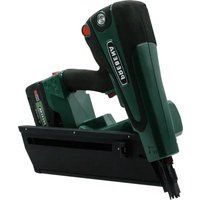
PKT-8RKP100 - Stapler Prebena - Free user manual and instructions
Find the device manual for free PKT-8RKP100 Prebena in PDF.


| Product type | Hybrid motor nailer (pneumatic/electric stapler) |
| Model | PKT-8-RKP100 |
| Brand | Prebena |
| Dimensions (without battery) | 362 x 142.4 x 392 mm |
| Weight (without battery) | 4670 g |
| Power supply | 18 V DC (CAS battery) + KT-1000 compressed air cartridge |
| Compatible nail types | Round head nails RKP/RK 20°, shank diameter 2.8-3.1 mm, length 65-100 mm |
| Magazine capacity | 30+8 nails (standard magazine for one strip) |
| Trigger systems | Single trigger with safety, contact trigger with automatic return |
| Depth adjustment | Adjustment wheel on trigger lock |
| Marking protection | Yes, removable plastic protector |
| Operating temperature | -5 °C to +45 °C |
| Maintenance | Exterior cleaning with soft cloth and mild detergent solution; no internal maintenance required |
| Safety | Trigger lock, dry-fire lock, safety devices |
| Spare parts and repairability | Use only original accessories; repairs exclusively by the manufacturer |
| Warranty | 1 year |
| Manufacturer | PREBENA, Seestraße 20-26, D-63679 Schotten, Germany |
Frequently Asked Questions - PKT-8RKP100 Prebena
User questions about PKT-8RKP100 Prebena
0 question about this device. Answer the ones you know or ask your own.
Ask a new question about this device
Download the instructions for your Stapler in PDF format for free! Find your manual PKT-8RKP100 - Prebena and take your electronic device back in hand. On this page are published all the documents necessary for the use of your device. PKT-8RKP100 by Prebena.
USER MANUAL PKT-8RKP100 Prebena
Original Operating Manual for Motor-Powered Hybrid Fastener Driver Tools
natural_image
Technical line drawing of a mechanical assembly with no visible text or symbolsPKT-8-RKP100
PKT-8-RKP100-LM
PKT-8-RKP100-SET
PKT-8-RKP100-SET4
PKT-8-RKP100-LM-SET
PKT-8-RKP100-LM-SET4

natural_image
Three circular icons showing a person wearing head, glasses, and using a device (no text or symbols)Bedeutung
Bedeutung
natural_image
Technical line drawings of mechanical components, showing two views of a bracket assembly (no text or symbols)Links: kurzes Magazin RKP, rechts: langes Magazin PR
natural_image
Technical line drawing of a car interior showing engine compartment and wiring (no text or symbols)natural_image
Technical line drawing of a mechanical assembly with no visible text or symbolsnatural_image
Abstract black-and-white geometric pattern with arrow-like shapes and vertical arrows (no text or symbols)natural_image
Simple line drawing of a trash bin with no text or symbols
Transportkoffer 31, 61
aufbewahren 62
Troubleshooting 66
Typenschild 23, 27
V
Information about the manual 4
Integral part of the fastener driving tool....5
Other applicable documents....6
Design features of the text....6
Design features of warning notices 7
Design features of notices to material damage 7
Definitions related to the tool 8
Safety 9
Proper use 9
Improper use....10
Safety notices 10
Personnel qualifications....17
Safety devices ....17
Personal protective equipment 19
Description 21
Scope of delivery 21
Information on the rating plate....22
Overview of the tool 23
Task and function 27
Control panel 28
Before operation....30
Unpacking the fastener driving tool 30
Checking the condition 30
Filling with compressed air 32
Fastening and removing the magazine 37
Loading and emptying the magazine....40
Attaching and removing rechargeable batteries....43
Turning on the tool....44
Checking the function 44
Operation 46
Selecting triggering process 46
Adjusting the insertion depth 47
Using imprint protection....49
Driving in nails 50
Setting down the fastener driving tool ....53
Using the crossbar hook....54
Venting the fastener driving tool 54
After operation....56
Turning off the tool 56
Removing the rechargeable battery 57
Emptying the magazine....57
Transport and storage 58
Packing the fastener driving tool 59
Transporting the fastener driving tool....60
Storing the fastener driving tool....61
Cleaning and maintenance....62
Cleaning 62
Maintenance 64
Eliminating malfunctions....65
Rectifying malfunctions in transport to the shot channel....65
Eliminating other malfunctions 66
Overview of malfunctions 67
Ordering accessories....70
Available accessories....70
Information about ordering nails....70
Technical data....71
Fastener driving tools 71
Compressed air cartridge KT-1000 72
Battery and batter charging station 73
Disposing of the fastener driving tool....74
Manufacturer's address 75
Warranty 76
Index 77
Information about the manual
This operating manual will help you to use the following motor-powered fastener driving tools safely, economically and as intended:
| Tool type | Equipment |
| PKT-8-PR100 | for paper-tape half head nails 34°, standard magazine with loading capacity for one nail strip, compressed air cartridge, without battery |
| PKT-8-PR100-LM | for paper-tape half head nails 34°, long magazine with loading capacity for two nail strips, compressed air cartridge, without battery |
| PKT-8-PR100-SET | for paper-tape half head nails 34°, standard magazine with loading capacity for one nail strip, compressed air cartridge, charger, rechargeable battery 5.5 Ah |
| PKT-8-PR100-SET4 | for paper-tape half head nails 34°, standard magazine with loading capacity for one nail strip, compressed air cartridge, charger, rechargeable battery 4.0 Ah |
| PKT-8-PR100-LM-SET | for paper-tape half head nails 34°, long magazine with loading capacity for two nail strips, compressed air cartridge, charger, rechargeable battery 5.5 Ah |
| PKT-8-PR100-LM-SET4 | for paper-tape half head nails 34°, long magazine with loading capacity for two nail strips, compressed air cartridge, charger, rechargeable battery 4.0 Ah |
| PKT-8-RKP100 | for plastic and paper-tape round head nails 20°, standard magazine with loading capacity for one nail strip, compressed air cartridge, without battery |
| PKT-8-RKP100-LM | for plastic and paper-tape round head nails 20°, long magazine with loading capacity for two nail strips, compressed air cartridge, without battery |
| Tool | Equipment |
| PKT-8-RKP100-SET | for plastic and paper-tape round head nails 20°, standard magazine with loading capacity for one nail strip, compressed air cartridge, charger, rechargeable battery 5.5 Ah |
| PKT-8-RKP100-SET4 | for plastic and paper-tape round head nails 20°, standard magazine with loading capacity for one nail strip, compressed air cartridge, charger, rechargeable battery 4.0 Ah |
| PKT-8-RKP100-LM-SET | for plastic and paper-tape round head nails 20°, long magazine with loading capacity for two nail strips, compressed air cartridge, charger, rechargeable battery 5.5 Ah |
| PKT-8-RKP100-LM-SET4 | for plastic and paper-tape round head nails 20°, long magazine with loading capacity for two nail strips, compressed air cartridge, charger, rechargeable battery 4.0 Ah |
Integral part of the fastener driving tool
This operating manual is an integral part of the fastener driving tool.
▶ Always keep this operating manual available for the users in the compartment provided for it in the transport case included with delivery.
▶ If the operating manual is lost or has become illegible, request a new copy from the manufacturer.
▶ If you sell the fastener driving tool or convey it to a third party by some other means, deliver the operating manual together with it.
▶ Make certain this operating manual is available for every user.
▶ Do not throw away this operating manual.
Other applicable documents
This manual includes the following documents:
- Operating manual for cartridge KT-1000
- If the fastener driving tool was delivered with a rechargeable battery and charger: Operating manual for rechargeable battery and charger
• Declaration of Conformity - Spare parts list
Design features of the text
Text elements of this operating manual are designed as follows:
Normal text
- Bulleted lists
– Second level bulleted lists
▶ Series of steps
i Tips for using the tool.
Design features of warning notices

DANGER
Notices with the word DANGER warn of a dangerous situation leading to death or serious injuries.

WARNING
Notices with the word WARNING warn of a dangerous situation that may possibly lead to death or serious injuries.

CAUTION
Notices with the word CAUTION warn of a situation that may to slight or moderate injuries.

ENVIRONMENTAL PROTECTION
Notices with the word ENVIRONMENTAL PROTECTION warn of actions that may lead to damage to the environment.
Design features of notices to material damage
| ATTENTION! | |
| These notices warn of a situation that will lead to material damage and limited functionality. | |
Definitions related to the tool
Motor-powered hybrid fastener driving tools are referred to in this operating manual in shortened form as "fastener driving tools" or, when clear from the context, as "tools."
Definition of the tool sides
The sides of the fastener driving tool are defined as follows relative to the direction of motion of the nails:
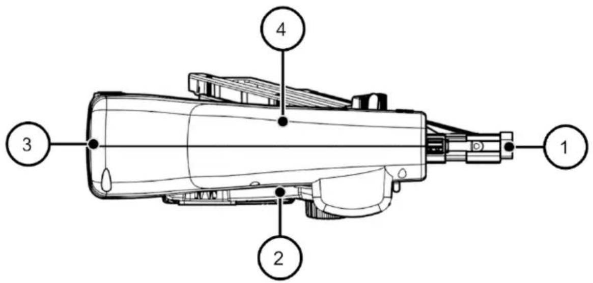
| 1 | front: tool tip |
| 2 | right |
| 3 | rear |
| 4 | left |
Safety
Failure to comply with the safety instructions in this operating manual may lead to serious accidents with severe or even fatal injuries.
▶ Make note of and follow all warnings and notices in this operating manual and on the fastener driving tool while working with the fastener driving tool.
Proper use
The fastener driving tools described here are hand-guided, motor-powered hybrid power tools. They are used to drive nails into wood materials with strength C30 in accordance with EN 338 and a maximum bulk density of 460 kg/m 3 .
Use of the fastener driving tool on other materials is only permitted after consultation with the manufacturer.
The allowable nail types are:
- RKP: Round head nail, in paper-tape nail strip
- PR: Half head nail, in paper-tape nail strip
The tool is also able to process round head nail type RK with plastic-tape nail strips.
Observing safety requirements
Proper use also includes:
- complying with accident prevention regulations and the requirements and standards in force at the operation site,
- observing and following all the instructions specified in this operating manual, especially the safety instructions.
Improper use
Any usage other than what is described here is improper and therefore contrary to the designated usage.
The following types of usage in particular are classified as improper:
- Operation by persons who do not know how to use fastener driving tools and the materials used with them
• Operation with the safety device bypassed - Use of nail types not specified in this operating manual
- Operation with compressed air cartridges other than those named in this manual
• Operation with materials other than those named in this manual - Operation with rechargeable batteries other than those named in this manual
Consequences of improper usage
Improper usage can lead to serious personal injuries and material damage.
Improper usage will also cause claims under the warranty or liability to be voided. The manufacturer assumes no liability resulting from improper usage.
Safety notices
General power tool safety warnings
WARNING Read all safety warning and all instructions.
Failure to follow the warnings and instructions may result in electric shock, fire and/or serious injury.
Save all warnings and instructions for future reference.
1. Work area safety
Keep work area clean and will lit. Cluttered or dark areas invite accidents.
Do not operate power tools in explosive atmospheres, such as in the presence of flammable liquids, gases or dust. Power tools create sparks which may ignite the dust or fumes.
Keep children and bystanders away while operating a power tool. Distractions can cause you to lose control.
2. Electrical safety
Avoid body contact with earthed or grounded surfaces, such as pipes, radiators, ranges and refrigerators. There is increased risk of electric shock if your body is earthed or grounded.
Do not expose power tools to rain or wet conditions. Water entering a power tool will increase the risk of electric shock.
3. Personal safety
Stay alert, watch what you are doing and use common sense when operating a power tool. Do not use a power too while you are tired or under the influence of drugs, alcohol or medication.
A moment of inattention while operating power tools may result in serious personal injury.
Use personal protective equipment. Always wear eye protection. Protective equipment such as dust mask, non-skid safety shoes, hard hat, or hearing protection used for appropriate conditions will reduce personal injuries.
Prevent unintentional starting. Ensure the switch is in the off-position before connecting to power source and/or battery pack, picking up or carrying the tool. Carrying power tools with your finger on the switch or energising power tools that have the switch on invites accidents.
Do not overreach. Keep proper footing and balance at all times.
This enables better control of the power tool in unexpected situations.
Dress properly. Do not wear loose clothing or jewellery. Keep your hair, clothing and gloves away from moving parts. Loose clothes, jewellery or long hair can be caught in moving parts.
4. Power tool use and care
Do not force the power tool. Use the correct power tool for your application. The correct power tool will do the job better and safer at the rate for which it was designed.
Do not use the power tool if the switch does not turn it on and off. Any power tool that cannot be controlled with the switch is dangerous and must be repaired.
Disconnect the plug from the power source and/or the battery pack from the power tool before making any adjustments, changing accessories, or storing power tools. Such preventive
safety measures reduce the risk of starting the power tool accidentally.
Store idle power tools out of the reach of children and do not allow persons unfamiliar with the power tool or these instructions to operate the power tool. Power tools are dangerous in the hands of untrained users.
Maintain power tool. Check for misalignment or binding of moving parts, breakage of parts and any other condition that may affect the power tool's operation. If damaged, have the power tool repaired before use. Many accidents are caused by poorly maintained power tools.
Use power tool, accessories and tool bits etc. in accordance with these instructions, taking into account the working conditions and the work to be performed. Use the power tool for operations different from those intended could result in a hazardous situation.
5. Battery tool use and care
Recharge only with the charger specified by the manufacturer. A charger that is suitable for one type of battery pack may create a risk of fire when used with another battery pack.
Use power tools only with specifically designated battery packs. Use of any other Û attery packs may create a risk of injury and fire.
When battery pack is not in use, keep it away from other metal objects, like paper clips, coins, keys, nails, screws or other small metal objects, that can make a connection from one terminal to another. Shorting the battery terminals together may cause burns or a fire.
Under abusive conditions, liquid may be ejected from the battery; avoid contact. If contact accidentally occurs, flush with water. If liquid contacts eyes, additionally seek medical help. Liquid ejected from the battery may cause irritation or burns.
Do not use a battery pack or tool that is damaged or modified. Damaged or modified batteries may exhibit unpredictable behaviour resulting in fire, explosion or risk of injury.
Do not expose a battery pack or tool to fire or excessive temperature. Exposure to fire or temperature above 130 °C may cause explosion.
Follow all charging instructions and do not charge the battery pack or tool outside the temperature range specified in the instructions. Charging improperly or at temperatures outside the specified range may damage the battery and increase the risk of fire.
6. Service
Have your power tool serviced by a qualified repair person using only identical replacement parts. This will ensure that the safety of the power tool is maintained.
Safety instructions for fastener driving tools
- Always assume that the tool contains fastener. Careless handling of the fastener driving tool can result in unexpected firing of fastener and personal injuries.
- Do not point the tool towards yourself or anyone nearby. Unexpected triggering will discharge the firing of fastener and personal injuries.
- Do not actuate the tool unless the tool is placed firmly against the workpiece. If the tool is not in contact with the workpiece, the fastener may be deflected away from your target.
- Disconnect the tool from the power source when the fastener jams in the tool. While removing a jammed fastener, the fastener driving tool may be accidentally activated if it is plugged in.
- Use caution while removing a jammed fastener. The mechanism may be under compression and the fastener may be forcefully discharged while attempting to free a jammed condition.
- Do not use this fastener driving tool for fastening electrical cables. It is not designed for electric cable installation and may damage the insulation of electric cables thereby causing electric shock or fire hazards.
Preventing explosion hazards
Serious or fatal injuries possible due to explosion.
▶ Never use the fastener driving tool in places subject to a danger of explosion.
▶ Never operate the fastener driving tool with oxygen or with any other flammable gases or gas mixtures.
▶ Do not expose the compressed air cartridge to temperatures above 100 °C.
Preventing serious or fatal injuries
Serious or fatal injuries possible if the fastener driving tool is used incorrectly.
The nails have high penetrating power! Never point the fastener driving tool at yourself, other persons or animals.
▶ Always hold the tool while working by the insulated handle surfaces.
The fastener driving tool must only be triggered when the tool tip is pressed against the workpiece.
▶ Make certain you do not accidentally activate or touch the triggering mechanism. Be especially attentive of this when setting the tool down or changing your working position.
▶ Remove the rechargeable battery and vent the fastener driving tool before every maintenance task.
Ricocheting nails are also dangerous! Normally the fastener driving tool must only be triggered when the tool tip is pressed against the material.
▶ Do not drive nails into power lines, gas lines or water lines.
Serious or fatal injuries possible if unauthorized changes are made to the fastener driving tool.
▶ Do not make any changes to the fastener driving tool.
▶ Make certain the safety devices are not bypassed or made non-functional in some other way.
▶ Use the fastener driving tool only with the compressed air cartridge specified in this operating manual.
▶ Use the fastener driving tool only with the rechargeable battery specified in this operating manual.
▶ Use the fastener driving tool only with the nail types specified in this operating manual.
Danger of asphyxiation for children playing packaging films.
▶ Do not allow children to play with the packaging film.
▶ Keep the packaging material where it is inaccessible for children.
Preventing risks of injury
Injuries possible if the fastener driving tool is used incorrectly.
▶ Always keep the fastener driving tool in the transport case and where it is inaccessible for children and other unauthorized persons.
▶ Never operate or transport the fastener driving tool with the compressed air cartridge inserted.
▶ Wear safety goggles and sturdy work clothes when operating the fastener driving tool.
▶ Hold the fastener driving tool so that you cannot be injured by a possible recoil.
▶ Use the fastener driving tool only when you have a secure footing.
Injuries possible on the sharp tips of the nails.
▶ Wear sturdy protective gloves when handling the fastener driving tool and especially while loading it.
Hearing impairment possible due to loud operating noises.
▶ Wear hearing protection while operating the fastener driving tool.
Injuries due to recoil possible during operation.
▶ Use the fastener driving tool only when you have a secure footing.
▶ Make certain your hands remain warm and dry while operating the fastener driving tool.
▶ Hold the fastener driving tool securely, but without too much hand pressure.
Injuries possible due to compressed air.
▶ Make certain the discharged air is not directed at persons, animals or body parts.
▶ Make certain all the parts of the compressed air supply are in flawless condition.
Preventing material damage
Damage or malfunctions in the fastener driving tool possible if operated improperly.
▶ Never open the housing of the fastener driving tool.
▶ Do not use the fastener driving tool if it has been dropped or is damaged.
| DANGER | |
 | Risk of death due to operating a faulty fastener driving tool.Only the manufacturer is permitted to open the tool and carry out repairs.► If the tool is damaged, send it in to the manufacturer for repairs (see manufacturer's address on page 75). |
Personnel qualifications
All persons who work with or on the fastener driving tool must have the following proficiencies and experience:
• Proficiency in working with fastener driving tool
- Ability to estimate the hazards associated with fastener driving tools and proficiency for averting these hazards
- Knowledge of the applicable industrial safety regulations at the workplace
- Familiarity with the required protective clothing
- Familiarity with the notices and instructions in the operating manual and the other materials included with delivery
Persons who use the fastener driving tool in the commercial sector must also be trained regarding the special risks in their workplace.
Persons without the proficiencies described above may only operate the fastener driving tool under the supervision of and after having been instructed by an experienced and qualified person.
Safety devices
Triggering safety device
Fastener driving tools are equipped with a triggering safety device on the tool tip. The trigger can only be enabled if the triggering safety device is pressed in.
| WARNING | |
 | Very severe injuries when operating the fastener driving tool with a faulty or bypassed triggering safety device.► Use the fastener driving tool only with a functioning triggering safety device.► Trigger the fastener driving tool only when the tool tip is firmly pressed against the material. |
Blank safety device
The fastener driving tool is equipped with a blank safety device. The blank safety device blocks the triggering mechanism when there are only 5–8 nails in the magazine.
Information signs on the fastener driving tool
The following mandatory signs are imprinted on the base of the fastener driving tool:
Mandatory sign

Meaning
Wear hearing protection while operating the fastener driving tool.

Wear safety goggles while operating the fastener driving tool.

Read this operating manual before startup.
The following symbol is attached to the front of the fastener driving tool:
Pictograms

Meaning
Markings and warnings for tools with contact actuation capability.
▶ Do not leave your finger on the trigger when the device is picked up, moved between work areas and positions, or when walking, as leaving your finger on the trigger can lead to unintended operation.
▶ In the case of devices with switchable triggering, always check that the device is set to the correct mode before use.
▶ Do not use this tool in contact actuation for applications such as closing boxes or crates and fitting transportation safety systems on trailers and lorries.
▶ Be careful when changing from one driving location to another.
Personal protective equipment
The fastener driving tool generates nails, compressed air and noise.
▶ Wear suitable personal protective equipment for all tasks with the fastener driving tool.
▶ Take note of and follow the regulations at the place where the tool is used when putting together the protective equipment.
Suitable protective equipment includes the following elements:
- Safety helmet
- Sturdy protective gloves
- Safety goggles
- Close fitting protective clothing
- Safety shoes with steel toecaps and non-slip soles
- Hearing protection
Description
Scope of delivery
The following parts are included in the scope of delivery of all fastener driving tools:
- Fastener driving tool
- Compressed air cartridge KT-1000
- Plastic transport case
• This operating manual
• Declaration of Conformity - Spare parts list
Tools with additional "SET"
Tools with additional "SET" are delivered with:
- 1 charger
• 1 rechargeable battery 5.5 Ah - Operating manual for charger and rechargeable battery
Tools with additional "SET4"
Tools with additional "SET4" are delivered with:
- 1 charger
• 1 rechargeable battery 4 Ah - Operating manual for charger and rechargeable battery
Tools with additional "LM"
Tools with addition "LM" have a long magazine
• for 60 round head nails RKP
• or 80 half head nails PR
Tools without addition
Tools without addition have a short magazine
• for 30 round head nails RKP
• or 40 half head nails PR
Information on the rating plate
The rating plate is pasted onto the housing. It contains the following information:
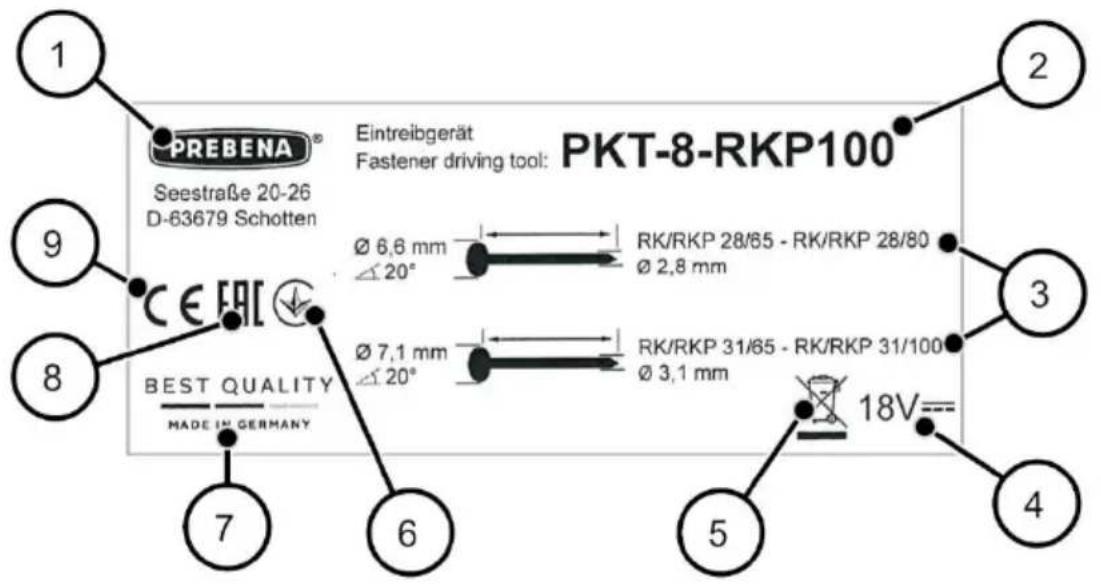
| 1 | Manufacturer's specifications |
| 2 | Type designation of the fastener driving tool |
| 3 | Type designation of the nails used |
| 4 | Power supply |
| 5 | Notice regarding disposal |
| 6 | National mark of conformity for Ukraine |
| 7 | Made in Germany |
| 8 | EAC marking |
| 9 | The CE mark (the product meets the requirements of the standards listed in the Declaration of Conformity) |
Overview of the tool
Overview of magazine
Your fastener driving tool is equipped with one of the following magazines:
- Short magazine for 1 strip of round head nails RKP/RK
- Long magazine for 2 strips of round head nails RKP/RK
- Short magazine for 1 strip of half head nails PR
- Long magazine for 2 strips of half head nails PR
The magazines are labeled with "RKP" or "PR" for the respective nail type.
A magazine for round head nails has a flatter angle than a magazine for half head nails:
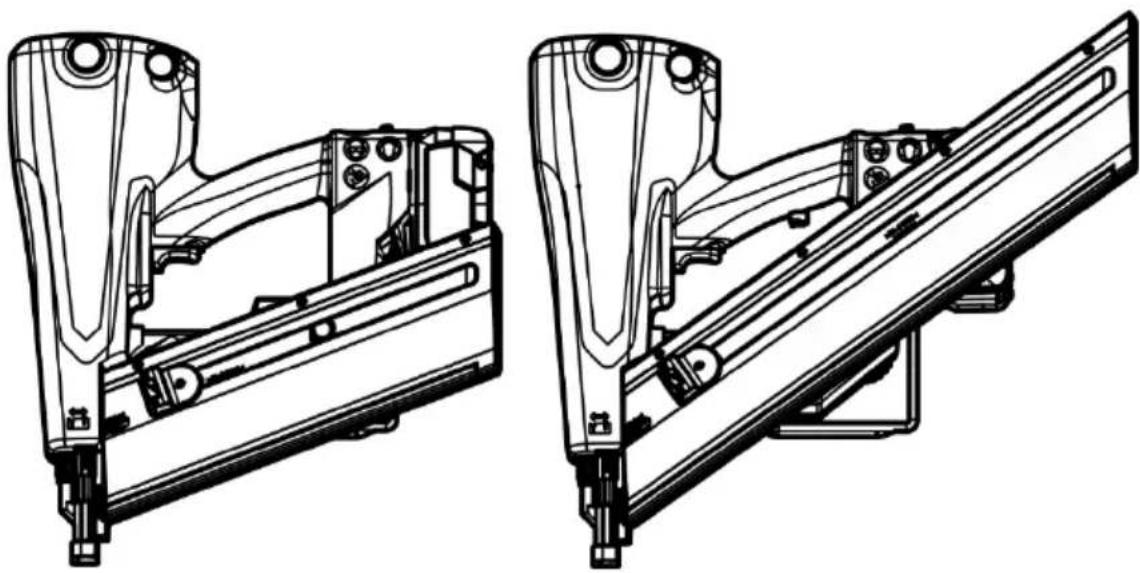
natural_image
Technical line drawings of two mechanical assembly components (no text or symbols)Left: short magazine RKP, right: long magazine PR

Long and short magazine of the same nail type are interchangeable.
Magazines of the different nail type are not interchangeable.
Left side of the tool
The figure shows the PKT-8-RKP100 tool with short magazine.
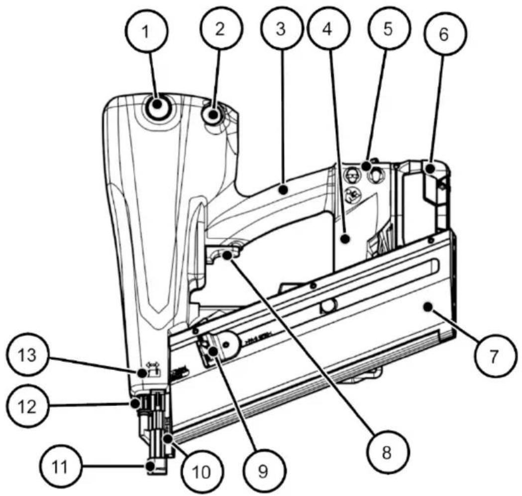
| 1 | Pressure indicator |
| 2 | Venting button |
| 3 | Handle |
| 4 | Base |
| 5 | Mandatory sign |
| 6 | Battery |
| 7 | Magazine (here: short, for round head nails) |
| 8 | Triggering mechanism |
| 9 | Pusher, with grooved pulling surfaces and metal tab for retainer |
| 10 | Tool tip |
| 11 | Triggering safety device with attached imprint protection |
| 12 | Depth adjustment |
| 13 | Depth adjustment pictogram |
Right side of the tool
The figure shows the PKT-8-PR100LM tool with long magazine.
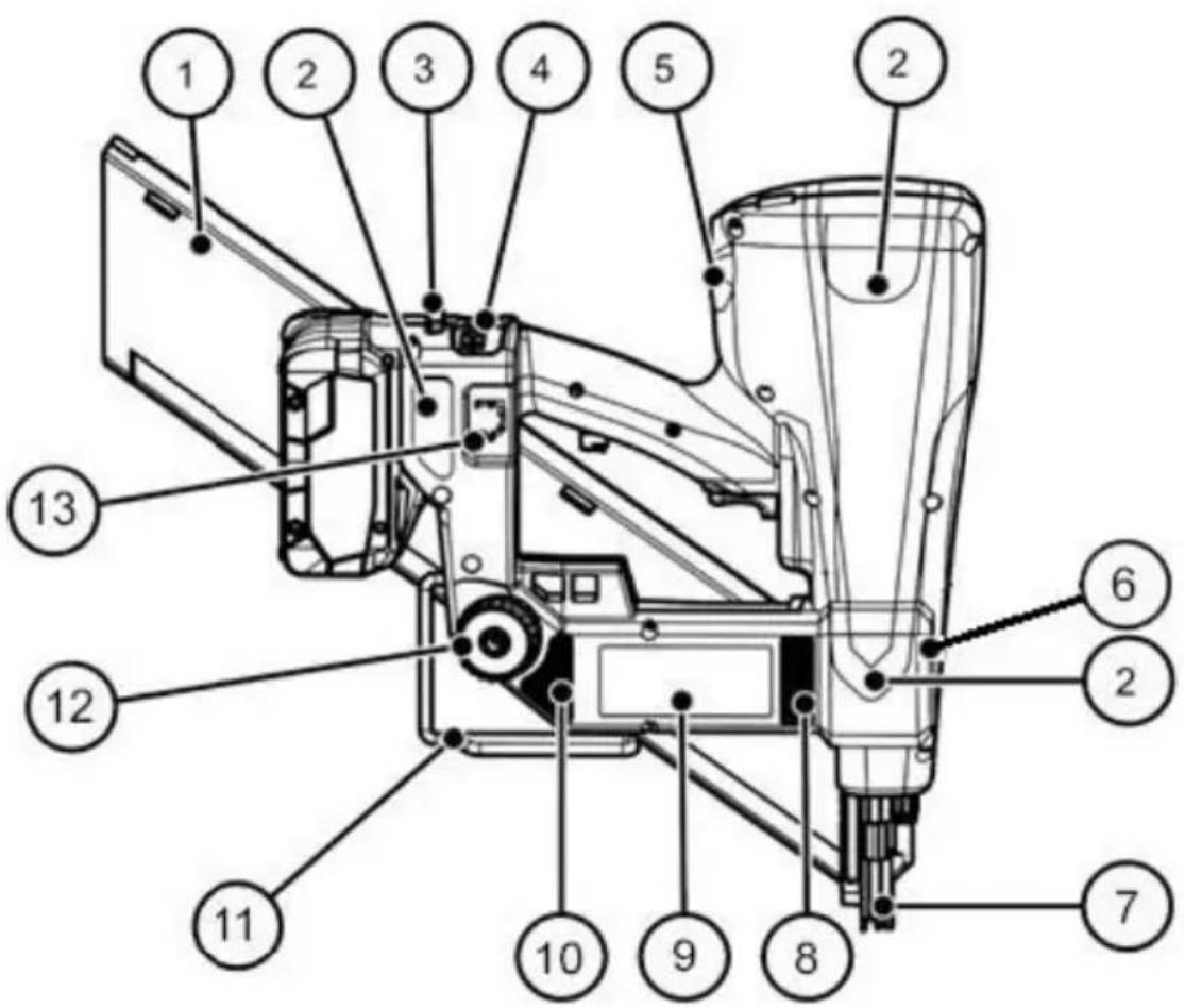
| 1 | Magazine (here: long, for half head nail) |
| 2 | Padded area (3 areas) |
Description
| 3 | Button for releasing the button |
| 4 | Control panel |
| 5 | Connecting thread for compressed air cartridge and protective plug |
| 6 | Pictograms; Markings and warnings for tools with contact actuation capability. |
| 7 | Triggering safety device without imprint protection |
| 8 | Exhaust air opening for cooling |
| 9 | Rating plate |
| 10 | Air intake opening for cooling |
| 11 | Crossbar hook |
| 12 | Thumbscrew for fastening and releasing the magazine |
| 13 | Holder for the imprint protection |
Task and function
Task
Fastener driving tool PKT-8-RKP100 drives in round head nails 65-100 mm long with a shaft diameter of 2.8–3.1 mm.
Fastener driving tool PKT-8-PR100 drives in half head nails 65-100 mm long with a shaft diameter of 2.8–3.1 mm.
The nails may only be driven into wood materials with a maximum strength of C30 in accordance with EN 338.
Functional principle
The nails are driven into the wood material by compressed air. The energy sources are the pressure accumulator, which can be filled with cartridge KT-1000, and the rechargeable battery.
The tool has two triggering processes for nail driving:
Single triggering with safety follow-up
A triggering process that allows one single driving process generated by the triggering mechanism after the triggering safety device has been activated. Additional driving processes can only be triggered if the triggering mechanism and triggering safety device have returned to the original position.
Contact triggering with automatic reset
The triggering mechanism is printed and held. In this state, every time the triggering safety device is pressed within 5 seconds, a driving process is generated. After 5 seconds without any contact with the material, the tool goes back to single triggering.
For adjustments to the triggering process see page 46.
Control panel
Overview of the control panel
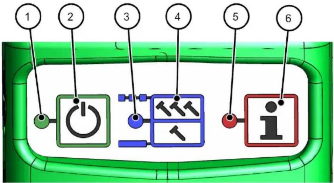
| 1 | Green LED: lit when the tool is turned on |
| 2 | ON/OFF button |
| 3 | Blue LED for triggering process (see page 46) |
| 4 | Select button for triggering process |
| 5 | Red LED: information about the operating state (see following see section) |
| 6 | Button has no function for this tool |
If no LEDs are lit, the tool is turned off.
Display of operating states
The tool may indicate the following operating states:
| Lighting behavior of the red LED/signal tone | Operating state |
| Not lit | The tool is ready for operation. |
| Lit continuously; tool beeps at 1-second interval | The battery charge is too low. The tool switches off after 10 seconds. |
| Flashes at 0.5-second interval | The operating temperature is too high. The tool switches off after 10 seconds. |
| Flashes at 1-second interval | Control malfunction. The tool switches off after 10 seconds. |
Before operation
Unpacking the fastener driving tool
| WARNING | |
 | Danger of asphyxiation for children playing packaging films.► Do not allow children to play with the packaging film.► Keep the packaging material where it is inaccessible for children. |
▶ Take the fastener driving tool out of the packaging.
▶ Remove all packaging materials such as films, filling material and the packaging carton.
▶ Keep the packaging material for later use.
▶ Keep the packaging material for transporting and storing the fastener driving tool.
The transport case is not packaging material! The case must be used to transport the fastener driving tool over long distances (see page 58) and to store it.
Checking the condition
Checking the external condition
▶ Check
- whether all the parts of the fastener driving tool and all accessory parts are securely fastened,
- whether parts of the fastener driving tool or accessories show signs of damage (dents, parts broken off),
- whether there are any foreign objects in the magazine or shot channel.
Checking the triggering safety device
The spring of the triggering safety device must not be damaged. To check the triggering safety device, follow these steps:
▶ Make certain the tool is turned off (no LEDs are lit, see also page 28).
▶ Remove the rechargeable battery.
▶ Press the spring-loaded tool tip down.
If the tool tip springs back freely, the spring of the triggering safety device is in good condition. Only then may the tool be placed in operation.

Scratches on the housing or magazine are not damage.


WARNING
Danger of injury when operating a damaged fastener driving tool or if an accessory is not fastened correctly.
▶ Check the condition of the fastener driving tool every time before using it.
▶ Use the tool only when it is in proper condition.
▶ If you cannot restore it to proper condition, have the tool repaired by the manufacturer's Customer Service (see page 75).
Filling with compressed air
Important information about compressed air cartridges
The fastener driving tool may only be filled with the compressed air cartridge KT-1000 included with delivery. An empty cartridge may only be refilled by the manufacturer or using the manufacturer's PKT series compressors. You can also buy a full compressed air cartridge in exchange for an empty compressed air cartridge in specialist stores.
The cartridge is sufficient for about 30 to 35 complete fillings of the fastener driving tool.
| WARNING | |
 | Danger of injury when filling improperly from the compressed air cartridge.The permitted pressure cannot be exceeded. The connecting thread may also be damaged.► Use only original compressed air cartridges type KT-1000 from the manufacturer.► Never try to fill an empty compressed air cartridge using your own resources.► Send empty cartridges back to the manufacturer (for address see page 75). |
Note as well:
- Use the compressed air cartridge KT-1000 for tools of the manufacturer only if the operating manual of the relevant tool explicitly specifies that cartridge type.
- Keep the valve of the compressed air cartridge and the screw connection of the fastener driving tool clean and protect them against damage. Remove dirt before screwing on the cartridge and before placing the tool in operation. Heavy soiling may only be removed by the manufacturer.
- Never use damaged compressed air cartridges.
-
The labeling on the compressed air cartridge must not be made illegible or removed.
-
Transport and store the compressed air cartridge only in the original packaging or in the transport case of the fastener driving tool.
- Remove the compressed air cartridge every time after the tool is filled. Do not transport the tool with the cartridge inserted.
Unscrewing the protective plug
The tool is delivered with a protective plug screwed into the thread for the compressed air cartridge. The protective plug protects the tool against penetration of dirt and the thread against damage.
| ATTENTION! | |
| Danger – damage to the tool.If the tool is operated without the protective plug, dirt and moisture can penetrate and damage the thread.► The protective plug should normally be left inserted.► Unscrew the protective plug only when you have to screw in the compressed air cartridge and screw it back in afterwards. | |
▶ Screw the protective plug (1) out of the thread (2):
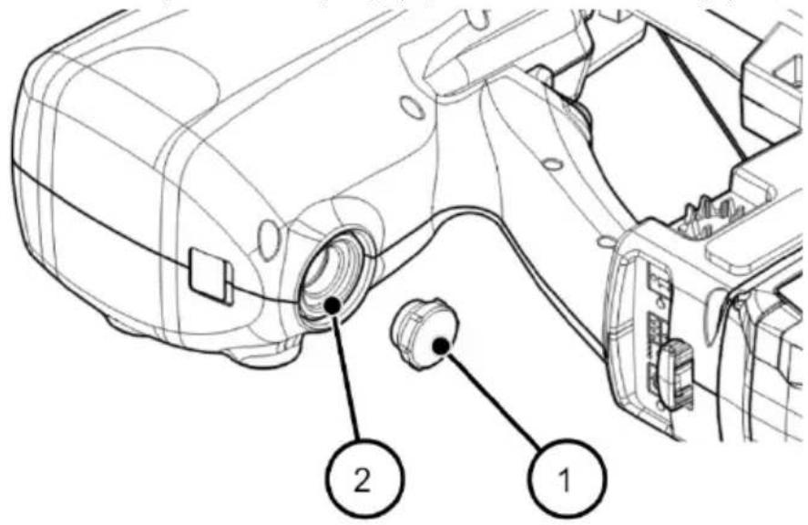
Using a compressed air cartridge
Screwing in the compressed air cartridge
▶ Check the condition of the fastener driving tool (see page 30).
▶ Take the protective cap off the cartridge.
▶ Check the screw connection on the tool and the thread of the compressed air cartridge for foreign objects and dirt.
▶ If necessary clean the connections.
| WARNING | |
 | Accidental triggering may result in severe or fatal injuries.Before connecting the cartridge, make certain on the control panel that the fastener driving tool is turned off.Empty the magazine.Do not point the tool at yourself, other people or animals. |
Filling with compressed air
▶ Screw the thread of the compressed air cartridge clockwise into the thread on the tool (1) finger-tight until you hear a slight sound of compressed air emerging from the small cartridge valve.
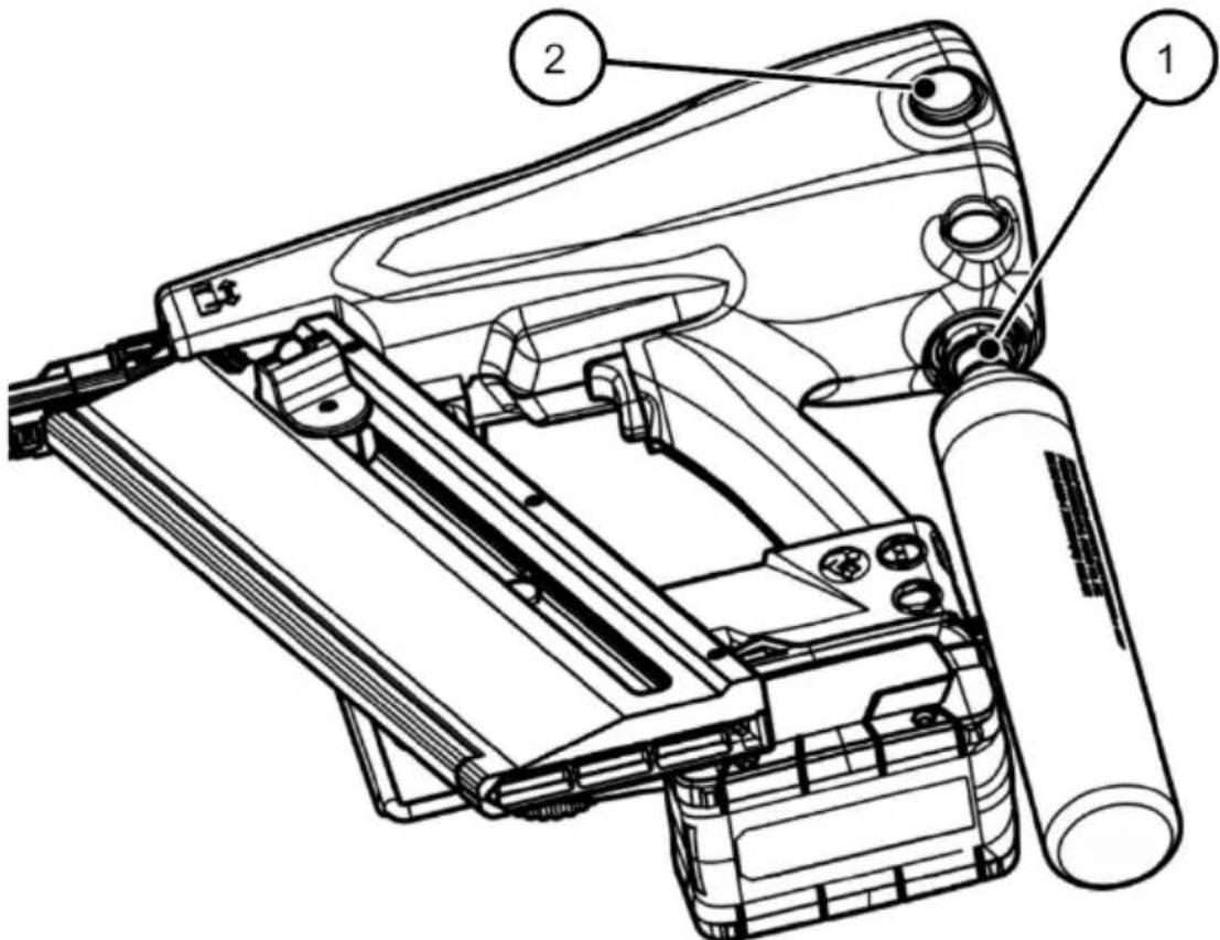
√ The tool can be heard filling for 1 to 2 seconds. On the pressure indicator (2) the pointer moves to the green range. The fastener driving tool is now filled with compressed air.
▶ Unscrew the cartridge counter-clockwise.
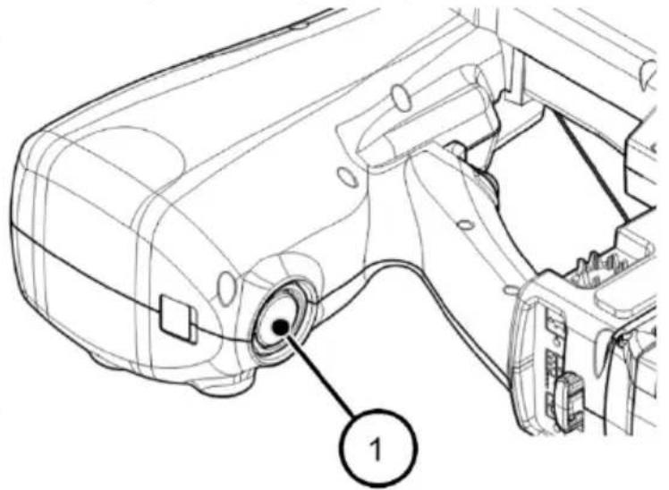
Screwing in the protective plug
▶ Screw the protective plug (1) back into the thread:
natural_image
Technical line drawing of a car interior showing engine compartment and wiring (no text or symbols)The protective plug must always be inserted when the cartridge is not inserted.
Checking the operating pressure
▶ Check the operating pressure on the pressure indicator (1):
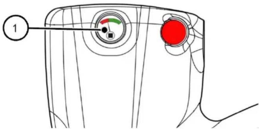
- If the pointer is in the green range, there is sufficient pressure present.
- If the pointer is in the red range, the pressure is not sufficient and the fastener driving tool must be refilled.

Excessive pressure in the compression chamber is diverted in the tool by a safety valve.
Fastening and removing the magazine
The procedure is identical for all magazine types (see page 23).
Fastening the magazine
The magazine is fastened by the fastened elements:
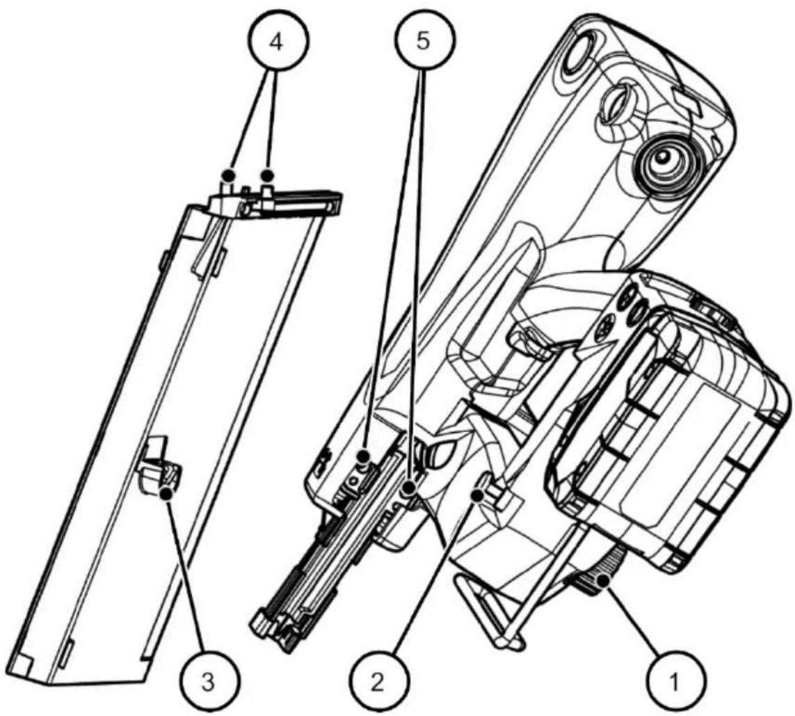
| 1 | Red thumbscrew |
| 2 | Clamping bolt on the tool |
| 3 | Bolt seating (open oblong hole) on the magazine |
| 4 | 2 pins on the magazine |
| 5 | 2 pin openings next to the shot channel |
To fasten the magazine in place, follow these steps:
▶ If necessary turn the thumbscrew (1) as far as it will go to the left.
The clamping bolt moves outward.
▶ Place the bolt seating (3) on the magazine under the bolt (2) on the tool.
▶ Push the magazine up a little so that the pins (4) on the magazine catch in the openings (5) next to the shot channel.
▶ When the bolt and pins are snugly seated, turn the thumbscrew (1) to the right as far as it will go.
The clamping bolt moves inward and clamps the magazine firmly in place.
√ The magazine is fastened in place.
Removing the magazine
▶ To release the magazine, turn the thumbscrew (1) as far as it will go to the left.
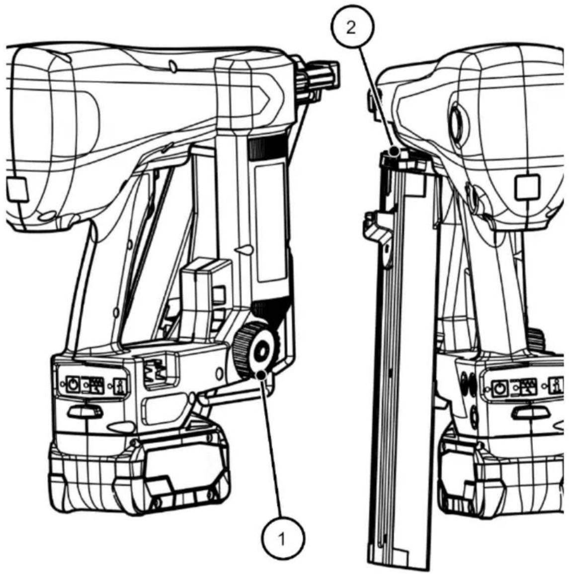
The magazine is moved outward and down and is released from the fastening (2).
▶ Now you can remove the magazine.
Loading and emptying the magazine
The procedure is identical for all magazine types (see page 23).
Loading the magazine
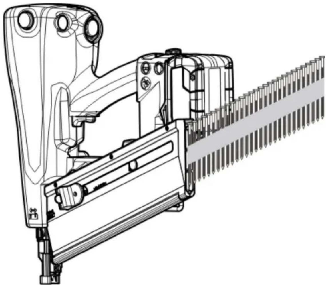
To fill the magazine with a nail strip, follow these steps:
▶ Hold the fastener driving tool with the tip pointing down.
▶ Let the nail strip slide forward into the magazine with the nail tips pointing forward:
natural_image
Technical line drawing of a mechanical assembly with no visible text or symbolsFor a long magazine ("LM") slide an additional nail strip into the magazine.
▶ With two fingers on the grooves (2), pull the pusher (1) back over the nail strip:
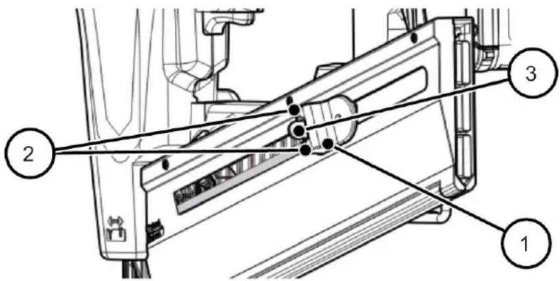
When the pusher has moved over the nail strip, the clamp (3) swings inward.
▶ Slowly let the pusher slide back
√ The nail strip is clamped in place. The magazine is loaded.
Emptying the magazine
To empty the magazine, follow these steps:
▶ Pull the pusher down on the grooves (1) while simultaneously pressing the tab (2) of the clamp (3):
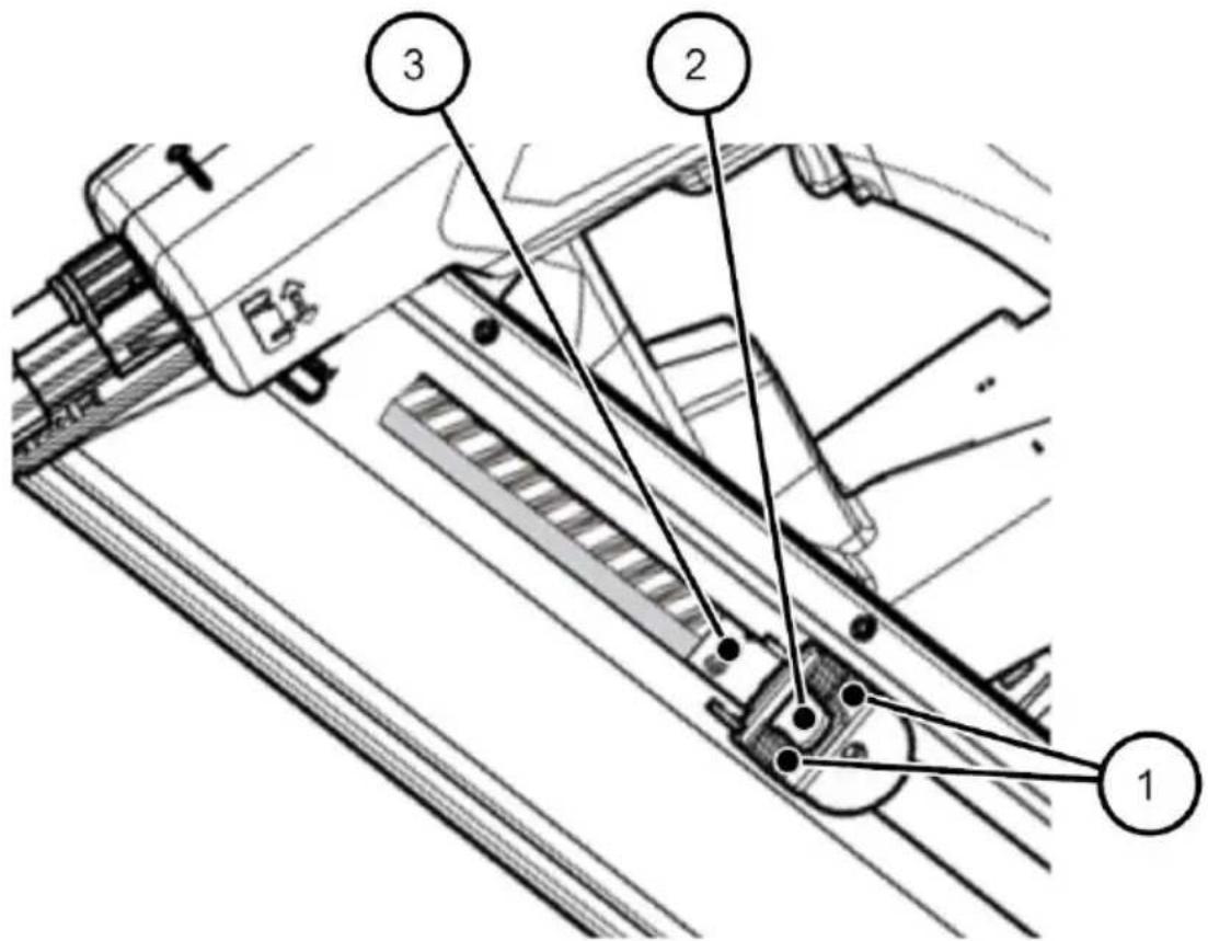
The clamp (3) swings outward and leaves the nail strip free.
▶ Let the pusher slide up.
▶ Push the nail strip out or let it slide out.
Attaching and removing rechargeable batteries
Fastener driving tools with an additional "SET" or "SET4" were delivered with a rechargeable battery and charger and the corresponding operating manual. The process for ordering batteries is accordingly not described in this operating manual.
▶ To attach the rechargeable battery, push it from front to back onto the battery interface on the bottom of the base (1):
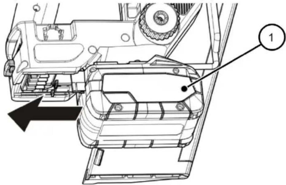
√ The battery locks into place when it reaches the end position.
▶ To remove the battery, press the red button (2):
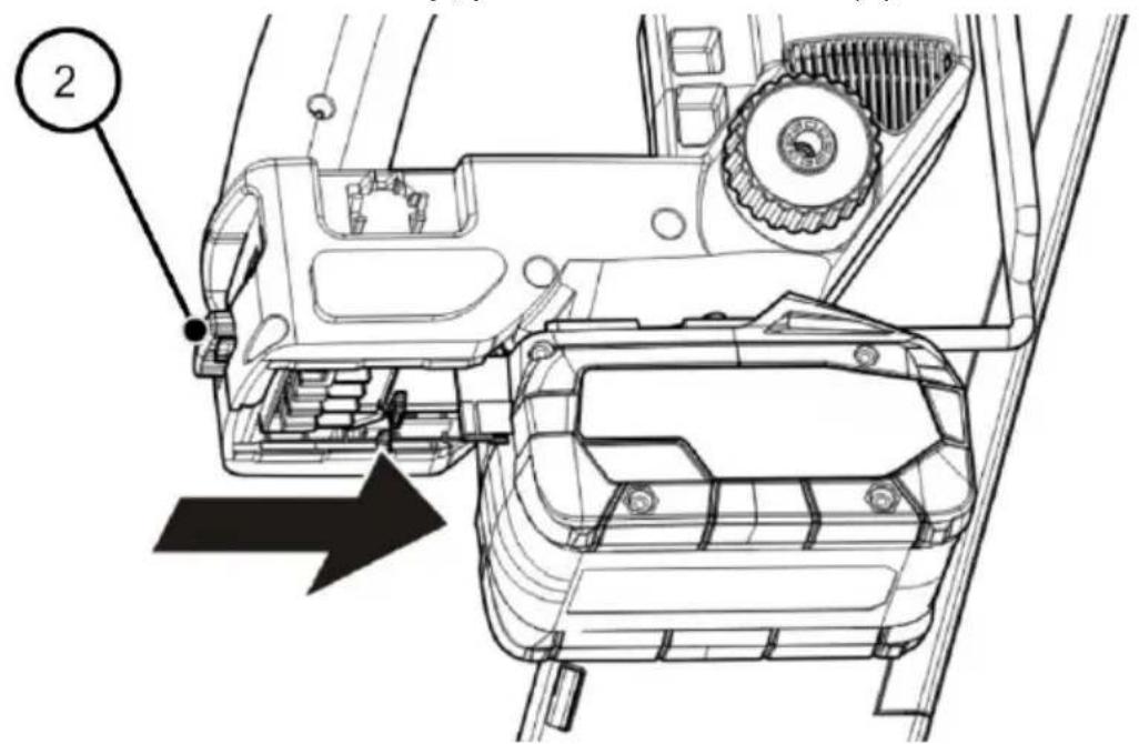
√ Then the battery can be pulled out towards the front.
Turning on the tool
The tool can only be turned on if the triggering mechanism and safety bar are not activated (in the original position).
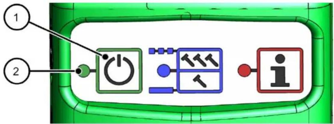
▶ Turn on the tool by pressing the ON/OFF button (1) on the control panel for at least 2 seconds:
flowchart
graph TD
    A["①"] --> B["Power Button"]
    C["②"] --> B
    B --> D["Device with T11 icon"]
    D --> E["Output: i"]
√ The green LED (2) is lit continuously.
The tool turns itself off automatically after 10 minutes if it has not been activated in any way.
Checking the function
| WARNING | |
 | Danger due to faulty fastener driving tool.The operator may injure himself or others and damage the materials in use.▶ Never use a fastener driving tool that is not working properly.▶ Send it to the manufacturer for repairs. |
▶ Set the tool tip of the fastener driving tool on a piece of wood at least ten centimeters thick.
▶ Choose the triggering process: Single triggering or contact triggering (see page 46).
▶ Trigger the fastener driving tool.
▶ Check the following items:
- Triggering occurs only when the triggering safety device is pressed in, in other words when the tool tip is firmly pressed against the wood.
- For single triggering: The depressed triggering safety device and the trigger button must always be moved back to the original position to be triggered again.
- For contact triggering: While the trigger button is depressed, every time the tool tip is pressed onto the material within 5 seconds, a nail is driven into the piece of wood.
- If the pause between contacts with the wood is more than 5 seconds, single triggering is set automatically.
▶ If the insertion depth is not correct, change the setting on the adjusting wheel (see page 47).
▶ Run a test on a piece of wood again and check the insertion depth.
√ If all functions are performed correctly, you can use the fastener driving tool.
Operation
Selecting triggering process
The fastener driving tool has two triggering processes:
- Single triggering
- Contact triggering
With the tool turned on, select the triggering process on the control panel:
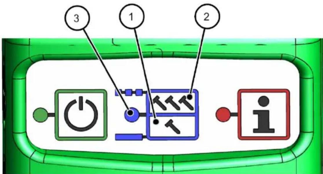
| Press "T" (1): | Single triggering | The blue LED (3) is lit continuously. |
| Press "TTT" (2): | Contact triggering | The blue LED (3) flashes. |

WARNING

Accidental triggering while changing the triggering setting may result in severe or fatal injuries.
▶ Do not point the fastener driving tool at yourself, other people or animals.

In particular, you must not use the contact release with automatic reset release setting for the following purposes:
- For applications such as closing boxes or crates and installing transport safety systems on trailers or trucks.
In these cases, set the selector switch on the control panel to single release.
Single triggering
With single triggering, pressing the triggering safety device against the material and then pressing the trigger button causes one single nail to be driven into the material.
Contact triggering with automatic reset
With contact triggering the trigger button is pressed and held. Then pressing the triggering safety device causes one nail to be driven into the material. If the triggering safety device is then pressed against the material an additional time within 5 seconds, another nail is driven in, etc.
After 5 seconds without activation or contact of the triggering safety device with the material, the tool reverts to the "single triggering" triggering process.
Adjusting the insertion depth
You can adjust the insertion depth for the nails. The fastener driving tool has a setting wheel on the triggering safety device to do this.
The pictogram on the side (item 2 in the diagram below) can be found on the housing of the fastener driving tool:
This pictogram shows the direction the setting wheel must point in to reduce or increase the insertion depth.

natural_image
Abstract black-and-white geometric pattern with arrow and triangle shapes (no text or symbols)Operation
▶ To reduce the insertion depth, turn the setting wheel (1) counterclockwise.
▶ To increase the insertion depth, turn the setting wheel (1) clockwise.
▶ Check the setting on the imprinted pictogram (3) in the tool tip.
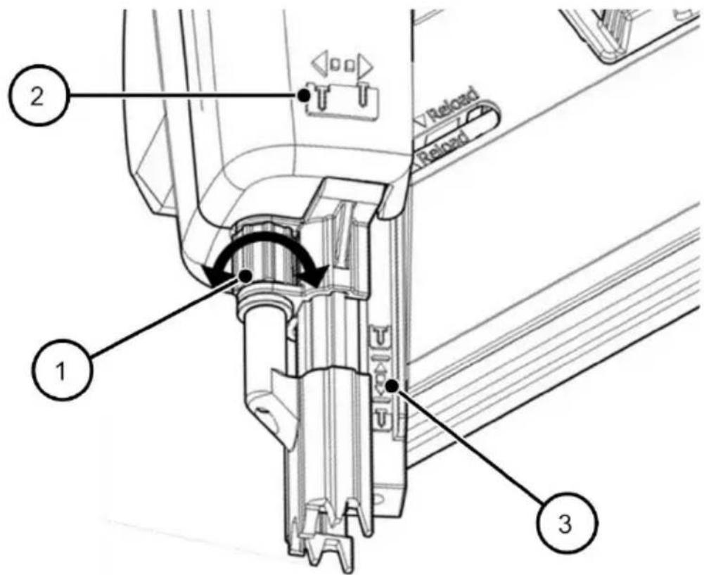
Checking the insertion depth
▶ Check for the correct insertion depth as described in section "Checking the function," page 44.
Using imprint protection
To protect decorative wood against damage, the fastener driving tool has imprint protection made of rubber for the triggering safety device.
If imprint protection is not needed, it can be inserted in the holder (1) provided for it on the right side of the tool base:
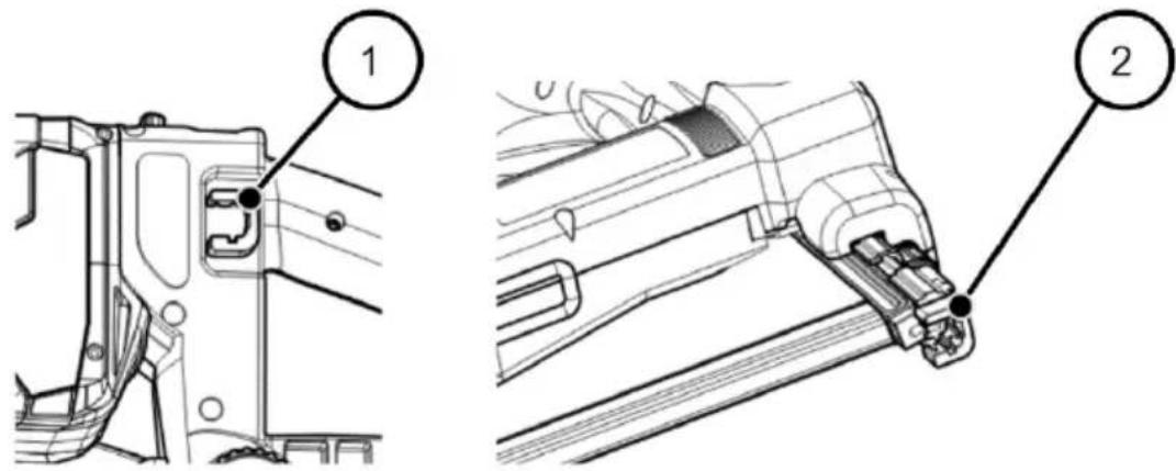
▶ To use imprint protection, attach it to the metal tips of the triggering safety device (2).
Driving in nails
| DANGER | |
 | Very serious or fatal injuries possible due to electrical shock.▶ Make certain before triggering that no power line, water line or gas line will be struck. |
 WARNING WARNING | |
 | Eye injuries and other injuries are possible during operation due to flying splinters.► Wear safety goggles and suitable protective clothing during operation.► Comply with applicable industrial safety regulations. |
 WARNING WARNING | |
 | Hearing damage is possible due to loud operating noise.► Wear suitable hearing protection.► Comply with applicable noise protection regulations. |

WARNING

Danger of injury due to nail driven in too deep, nail slipping or recoil.
▶ Use the fastener driving tool only for the material specified in this operating manual (see Designated use, page 9).
▶ Make certain the insertion depth is not greater than the thickness of the material.
▶ Press the fastener driving tool firmly on the material while triggering.
▶ Make certain the material is not too hard.
The insertion depth depends not only on the set insertion depth, but also on the hardness and thickness of the material.
▶ Make certain there is no one behind the material.
▶ Set a small insertion depth for testing.
▶ Check the function of the fastener driving tool with single triggering.
Triggering the fastener driving tool one time
To trigger the fastener driving tool one time, follow these steps:
▶ Choose triggering process "Single triggering with safety follow-up" by pressing the "T" button (trigger one time) on the control panel (see page 28). The blue LED is lit.
▶ Place the triggering safety device of the fastener driving tool on the material and press the fastener driving tool against the material.
▶ Press the triggering mechanism all the way down.
√ The nail is driven into the material.
▶ Release the triggering mechanism.
▶ Lift the fastener driving tool up off the material.
Triggering the fastener driving tool repeatedly
| WARNING | |
 | Accidental triggering may result in severe or fatal injuries.► Do not point the fastener driving tool at yourself, other people or animals.► Do not leave your finger on the trigger when the device is picked up, moved between work areas and positions, or when walking, as leaving your finger on the trigger can lead to unintended operation.► In the case of devices with switchable triggering, always check that the device is set to the correct mode before use.► Do not use this tool in contact actuation for applications such as closing boxes or crates and fitting transportation safety systems on trailers and lorries.► Be careful when changing from one driving location to another. |
 | |
▶ Choose triggering process "Contact triggering with automatic reset" by pressing the "TTT" button (trigger multiple times) on the control panel. The blue LED flashes.
▶ Press and hold the triggering mechanism.
▶ Place the triggering safety device of the fastener driving tool on the material and press the fastener driving tool briefly against the material.
A nail is driven into the material.
▶ Within 5 seconds, place the tool tip on the next desired position and briefly press the fastener driving tool.
Another nail is driven into the material.
You can repeat this process as long as you hold the triggering mechanism depressed and there are nails in the magazine.
▶ To end nail driving, release the triggering mechanism.
▶ Lift the fastener driving tool up off the material.
Reloading nails
The magazine has a blank safety device.
This prevents you from being able to trigger the fastener driving tool if there are only 5–8 nails in the magazine.
▶ Load new nail strips (see page 40).
Setting down the fastener driving tool
The fastener driving tool has a specified resting position. The tool has three padded areas on the right side for setting it down:
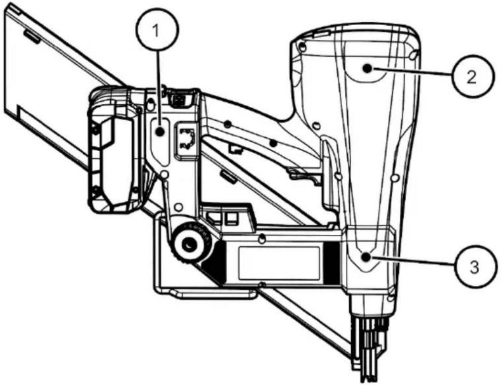
| 1 | Padded area under the handle |
| 2 | Rear padded area |
| 3 | Tool tip padded area |
▶ If work will be interrupted for a few minutes, set the fastener driving tool down.
▶ Always set the fastener driving tool down so it is resting on the three padded areas.
Using the crossbar hook
The fastener driving tool has a crossbar hook (chevron hook) by which you can briefly fasten the tool to a roof batten or similar object. The crossbar hook is located on the bottom of the fastener driving tool.
To be able to suspend the fastener driving tool, the crossbar hook must be turned to the side.
▶ Press the crossbar hook in a little (1):
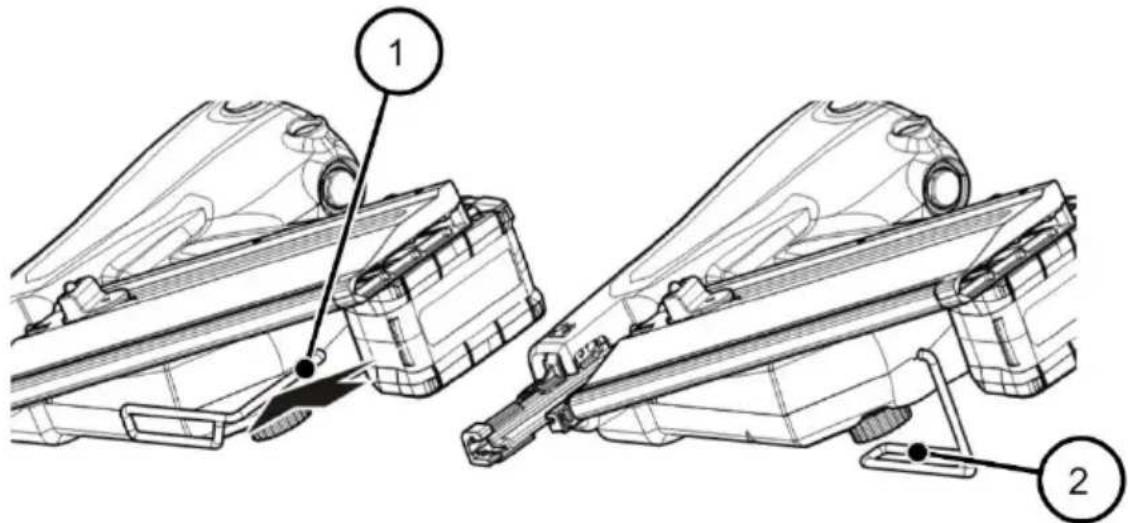
▶ Then turn the crossbar hook to the side (2).
√ Now you can suspend the fastener driving tool.
Venting the fastener driving tool
You can vent the fastener driving tool at any time as long as there is no compressed air cartridge connected. This may be necessary for example
• to remove condensation
- before fault rectification (before removing jammed nails, etc.).
▶ To vent the tool, press the red venting button (1):
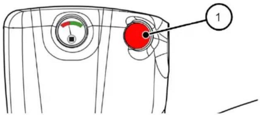
√ The tool can be heard venting.
After operation
| WARNING | |
 | Accidental triggering may result in severe or fatal injuries.► Do not point the fastener driving tool at yourself, other people or animals.► Turn off the tool after operation is complete and empty the magazine. |
After operation or extended interruptions in operation, carry out the steps described below.
Turning off the tool
▶ Turn off the tool by pressing the ON/OFF button (1) on the control panel for at least 2 seconds:

flowchart
graph TD
    A["1"] --> B["Power Button"]
    C["2"] --> B
    B --> D["Termit"]
    B --> E["Timer"]
    B --> F["Icon"]
√ If the green LED (2) is no longer lit, the tool is turned off. All the other LEDs are also not lit.
The tool turns itself off automatically after 10 minutes if it has not been activated in any way.
Removing the rechargeable battery
▶ To remove the battery, press the red button (1) on the base:
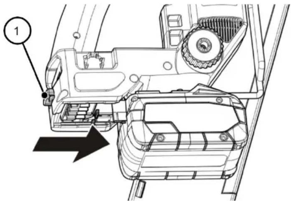
√ Then the battery can be pulled out towards the front.
Emptying the magazine
▶ Always empty the magazine after operation.
▶ To do this follow the instructions in section "Emptying the magazine" on page 42.
Transport and storage
| WARNING | |
 | Accidental triggering may result in severe or fatal injuries.Do not point the fastener driving tool at yourself, other people or animals during transport.If a cartridge is inserted, remove the cartridge for transport.Carry the fastener driving tool only by the handle.Do not touch the triggering mechanism during transport. |
| ATTENTION! | |
| Bumps or impacts may damage the fastener driving tool.► Do not drop the fastener driving tool.► Protect the fastener driving tool against bumping into obstacles. | |
Packing the fastener driving tool
The fastener driving tool and accessory parts may only be packed in the transport case included with delivery as shown here:
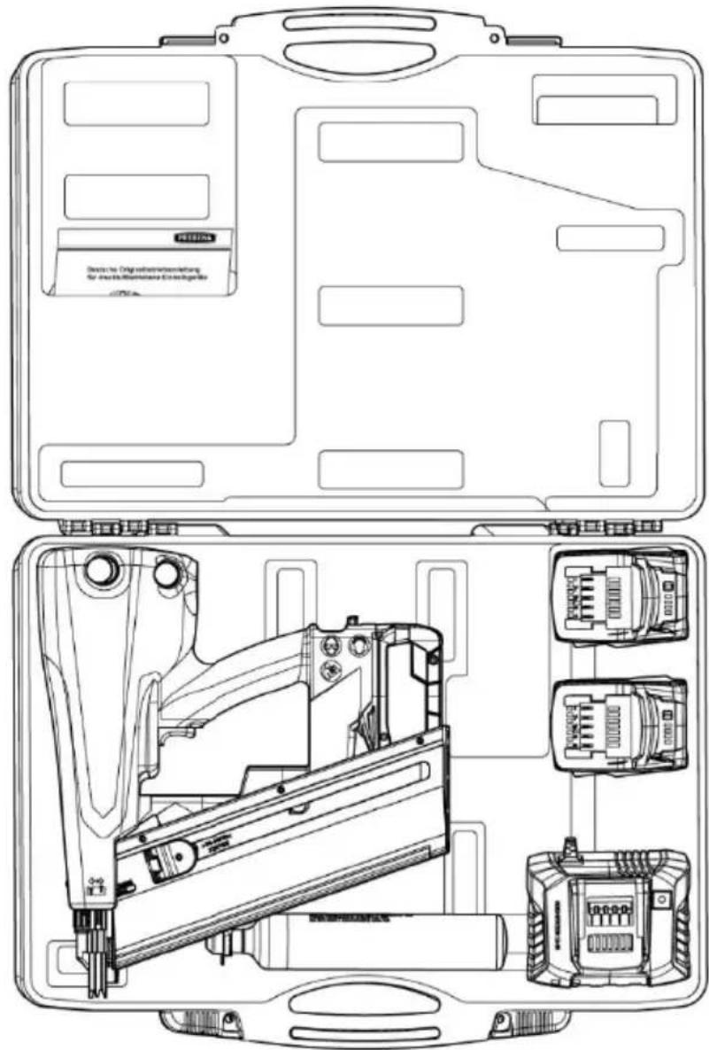
To pack the fastener driving tool in the case, follow these steps:
▶ Turn off the tool.
▶ Remove the rechargeable battery.
▶ Empty the magazine.
▶ Clean the tool (see page 62).
▶ Place the compressed air cartridge, fastener driving tool, rechargeable batteries and battery charging station in the transport case as shown above.
▶ Close the transport case.
Transporting the fastener driving tool
The type of transport determines whether you are transporting the fastener driving tool over short or long distances.
Short distances
Short distances are no longer than 10 meters in length.
Long distances
The following distances are considered "long distances" for transporting the fastener driving tool:
• Distances longer than 10 m,
• Distances that lead over an uncertain subsurface,
- Distances that must be covered in an unusual body position.
Transporting the fastener driving tool over short distances
▶ Turn off the tool.
▶ Carry the fastener driving tool by the handle with the tool tip pointing at the floor.
Transporting the fastener driving tool over long distances
▶ Turn off the tool.
▶ Remove the rechargeable battery.
▶ Pack the fastener driving tool in the transport case included with delivery.
▶ Carry the transport case by the handle to the desired operating location.
▶ Do not unpack the fastener driving tool until you reach the location where it will be used.
Storing the fastener driving tool
To protect the fastener driving tool against damage when it will not be used for an extended period, follow these steps:
▶ Vent the tool as described on page 54.
Pack the fastener driving tool and accessories in the transport case included with delivery as described on page 59.
▶ Store the transport case at room temperature in a dry and dust-free place.
Cleaning and maintenance
| WARNING | |
 | Accidental triggering may result in severe or fatal injuries.► Do not point the fastener driving tool at people or animals.► Always empty the magazine before working on the fastener driving tool. |
Cleaning
Carry out the following activities before cleaning work:
▶ Turn off the tool.
▶ Remove the rechargeable battery.
▶ Remove the magazine.
▶ Vent the tool.
Removing dirt and foreign objects
Dirt and foreign objects may settle on the tool, especially on movable parts and exposed interfaces. They can lead to malfunctions and must be removed immediately.
Parts of the tool to keep clean
The following parts of the tool in particular must always be kept free of dirt and foreign objects:
- Exhaust air opening and air intake opening
- Thread for the cartridge and the protective plug
- Magazine
- Thumbscrew and fastening bolt for the magazine
- Tool tip with imprint protection
- Battery interface (on the tool and on the battery)
- Shot channel (see diagram below, item 1)
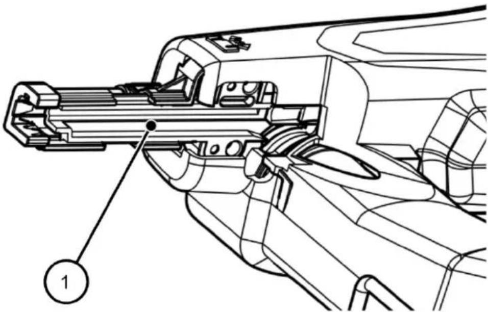
Procedure
To remove dirt and foreign objects, follow these steps:
▶ Vent the tool.
▶ Turn off the tool.
▶ Remove the rechargeable battery.
▶ Remove the magazine.
▶ Clean the exposed interface and movable parts of the tool with a clean cloth or brush, removing dirt and foreign objects.
Cleaning the housing and outer surfaces
| ATTENTION! | |
| Damage to the fastener driving tool or accessories due to unsuitable cleaning agent.► For cleaning use only a dry, slightly moistened cloth or a cloth moistened with a mild soap solution. | |
To remove light soiling, follow these steps:
▶ Wipe off the housing of the fastener driving tool with a dry cloth.
To remove heavy soiling, follow these steps:
▶ Wipe off the housing of the fastener driving tool with a cloth slightly moistened with a mild soap solution.
▶ Next wipe off the housing with a cloth slightly moistened with tap water.
▶ Then rub with a soft, dry cloth.
Maintenance
The fastener driving tool is maintenance-free.
Eliminating malfunctions


WARNING
Severe or fatal injuries are possible when operating a damaged or malfunctioning fastener driving tool.
▶ Empty the magazine.
▶ Do not use the fastener driving tool again until the malfunction has been eliminated.
ATTENTION!
The fastener driving tool can be damaged if repairs are made by unauthorized persons.
▶ Always have repairs to the fastener driving tool made by the manufacturer.
Rectifying malfunctions in transport to the shot channel
If there is a malfunction moving nails from the magazine to the shot channel, follow these steps:
▶ Vent the tool.
▶ Turn off the tool.
▶ Remove the rechargeable battery.
▶ Remove the magazine.
▶ Remove jammed nails and any other foreign objects from the shot channel and/or magazine.
If this measure does not eliminate the malfunction, contact the manufacturer's Customer Service.
Eliminating other malfunctions
If malfunctions have occurred on the fastener driving tool that you cannot remedy by yourself, contact the manufacturer's Customer Service.
▶ Do not perform any repair work on the fastener driving tool.
▶ Always have repairs to the fastener driving tool made by the manufacturer.
The overview below shows possible malfunctions and the actions which must be taken.
Overview of malfunctions
| Feature | Possible cause | Remedy |
| Fastener driving tool is losing air. | A seal is faulty. | ► Contact Customer Service (see page 75). |
| Safety valve or check valve faulty. | ||
| Operating pressure too high. | Too much compressed air was loaded from the cartridge. | If this occurs sporadically no measures are necessary. Excessive pressure in the compression chamber is diverted in the tool by a safety valve.If the problem occurs continuously:► Contact Customer Service (see page 75). |
| A valve is faulty. | ||
| Nails are not being driven in completely. | Operating pressure is too low. | ► Add more compressed air from the cartridge (see page 32).If the problem occurs continuously:► Contact Customer Service (see page 75). |
| The material you are using is too hard. | The nails may only be driven into wood materials with a maximum strength of C30 in accordance with EN 338. | |
| The insertion depth is set too low for the material. | ► Increase the insertion depth (see page 47). | |
| No nails are driven in when the fastener driving tool is triggered. | The magazine or shot channel are dirty. | ► Turn off the tool.► Remove the magazine.► Remove foreign objects from the shot channel and magazine. |
| Wrong nails are loaded in the magazine. | ► Emptying the magazine.► Fill the magazine with nails that are permitted for the magazine (see page 27). |
Eliminating malfunctions
| Feature | Possible cause | Remedy |
| Operating pressure is too low. | ▶ Add more compressed air from the cartridge (see page 32). | |
| The driving in process is not performed completely. | ▶ Contact Customer Service (see page 75). | |
| The red LED in the control panel is lit continuously and the tool beeps at a 1-second interval. | The battery charge is too low. The tool switches off after 10 seconds. | ▶ Charge the battery. |
| The red LED in the control panel is lit at a 0.5-second interval. | The operating temperature is too high. The tool switches off after 10 seconds. | ▶ Allow the tool to cool off for at least 15–30 minutes. |
| ▶ Check whether the exhaust air opening and air intake opening are free. ▶ Clean them if necessary. | ||
| The red LED in the control panel is lit at a 1-second interval. | Control malfunction.The tool switches off after 10 seconds. | ► Contact Customer Service (see page 75). |
| The tool will not turn on. | Trigger button or triggering safety device activated. | Move the trigger button or triggering safety device to the original position. |
| Tool cannot be filled with compressed air. | Compressed air cartridge empty. | Fill or replace the compressed air cartridge. |
| Connecting thread dirty. | Clean connecting thread. |
Ordering accessories
You can order accessory parts from the manufacturer.
▶ Use only the manufacturer's original accessories or accessories that have been approved by the manufacturer for use with the fastener driving tool.
▶ Use only the nail types that are specified on the rating plate of your fastener driving tool.
This is the only way to ensure the optimum function of the fastener driving tool and prevent possible damage to the fastener driving tool due to incorrect driving material.

This section contains information about the most important accessory parts only.
Information about other accessories can be found on the manufacturer's website.
Available accessories
The following accessory parts are available for the fastener driving tools:
• Nails (paper-tape nail strips)
- Compressed air cartridge KT-1000
- PKT series compressor
- Rechargeable batteries 5.5 Ah and 4.0 Ah
- Charger
Information about ordering nails
| ATTENTION! | |
| Damage to the fastener driving tool or accessories due to unsuitable nails.► Use only the nail types that are specified on the rating plate of your fastener driving tool. | |
Technical data
We reserve the right to make technical improvements
Fastener driving tools
| Tool PKT-8-: | PR100 | PR100-LM | RKP100 | RKP100-LM |
| Dimensions without battery (L x W x H): | 312 x 133.6 x 392 mm | 458 x 159 x 392 mm | 362 x 142.4 x 392 mm | 554 x 176 x 392 mm |
| Weight without battery: | 4605 g | 4825 g | 4670 g | 4960 g |
| Magazine: | For half head nails PR, paper-tape, inclined 34°, loading from the rear | For round head nails PR, paper- and plastic-tape, inclined 20°, loading from the rear | ||
| Magazine capacity: | 40+5 | 80+5 | 30+8 | 60+8 |
| Nail types: | PR28/65 – PR31/100 | RKP28/65 – RKP31/100 RK28/65 – RK31/100 | ||
| Nail length: | 65–100 mm | |||
| Nail shaft: | ∅ 2.8–3.1 mm | |||
| Triggering system: | Switchable triggering mechanism:• Single triggering with safety follow-up• Contact triggering with automatic reset | |||
| Motor: | Brushless DC motor | |||
| Power supply: | 18 V DC | |||
| Driving in speed: | 1.5 nails per second | |||
| Magazine system: | loading from the rear | |||
| Operating temperature: | -5 °C to +45 °C | |||
| Storage/ transport temperature: | Room temperature | |||
| Characteristic vibration values: (EN 60745) | 3.80 m/s2 | |||
| Kh=1.5 m/s2 | ||||
| Characteristic noise values: (EN 60745) | LWA,1s=101 dB | |||
| LpA,1s=90 dB | ||||
| LpCpeak<130 dB | ||||
| KpA, KWA=3 dB | ||||
Compressed air cartridge KT-1000
| Length: | 271.5 mm |
| Diameter: | ∅ 50 mm |
| Weight, empty cartridge: | 695 g |
| Weight, filled cartridge: | 800 g |
| Contents: | 0.36 l |
| Maximum container air pressure: | 300 bar |
| Number of fillings: | 30–35 |
| Operating temperature: | -5 °C to +45 °C |
| Storage and transport temperature: | Room temperature |
Battery and batter charging station
Use only original Metabo or CAS (Cordless Alliance System) battery packs and accessories.
| Approved CAS battery | Capacity | Voltg. | ||
| LiHD: | 8.0 Ah | 5.5 Ah | 4.0 Ah | 18 V |
| Li-Power: | 2.0 Ah | 4.0 Ah | 5.2 Ah | 18 V |
| Other technical data | 4 Ah | 5.5 Ah |
| Driving processes per charge: | approx. 670 | approx. 1000 |
| Charging time for normal charging tool: | approx. 80 min. | approx. 110 min. |
| Charging time for quick charging tool: | approx. 37 min. | approx. 51 min. |
| Weight: | approx. 585 g | approx. 990 g |
The technical specifications quoted are subject to tolerances (in compliance with the relevant valid standards).

Emission values
These values make it possible to assess the emissions from the power tool and to compare different power tools. The actual load may be higher or lower depending on the operating conditions, the condition of the power tool or the accessories. Please allow for breaks and periods when the load is lower for assessment purposes. Arrange protective measures for the user, such as organisational measures based on the adjusted estimates.
During operation the noise level can exceed 80 dB(A).

Wear ear protectors!
Disposing of the fastener driving tool
ENVIRONMENTAL PROTECTION

Environmental damage if not disposed of as required by environmental regulations.
▶ Clean the fastener driving tool before disposing of it.
The tool contains oil. Comply with the applicable requirements for disposing of oil.

natural_image
Simple line drawing of a trash bin with no text or symbols
▶ Never dispose of a fastener driving tool or parts of it in household waste.
▶ If you would like to dispose of the fastener driving tool, send it to manufacturer.
The manufacturer will ensure that the fastener driving tool is disposed of properly.
Manufacturer's address
PREBENA
The manufacturer guarantees the designated tool for 1 year from the date of purchase according to the following warranty conditions. The manufacturer guarantees correction of defects due to faulty material or manufacturing at no cost. Malfunctions or damage caused by improper handling will not be considered within the scope of free warranty repairs.
Only the manufacturer's original nails may be used. Failure to comply with this requirement shall render product liability and thus any claims under the warranty null and void. The warranty does not extend to wear parts such as O-rings, etc. The manufacturer may at its discretion honor the warranty by replacing the faulty part or with a replacement delivery. Any further claims shall be excluded.
To make a claim under the warranty, the warranty certificate, completely filled in with the dealer's stamp and date of purchase, or an invoice document containing the date and information as required according to the warranty certificate must be enclosed.
Shipping: The tool must be packaged carefully to protect it against breakage and sent to the manufacturer with full postage paid.
Warranty certificate
Model designation:
Date of purchase:
Dealer/consumer:
(stamp)
Index
A
Accessories 70
Available to order 70
Adjusting
Insertion depth 47
Selecting triggering process 46
After operation
Turning off the tool 56
Air intake opening 26
B
Backlash 15
Base 24
Battery 24
Attaching 43
Removing 43
Technical data 73
Battery charging 29
Battery, button for releasing 26
Belt hook
See crossbar hook 54
Blank safety device 53
Safety device 18
C
C30 (strength of wood) 27
Cartridge
See Compressed air cartridge 34
CAS battery
Technical data 73
Case 30, 60
CE mark 22
Checking
Accessory parts 30
Automatic changeover from contact
triggering to single triggering 45
Condition 30
Function 44
Insertion depth 48
Triggering 45
Checking the condition
Accessory parts 30
External damage 30
Triggering safety device 31
Checking the function 44
Chevron hook
See crossbar hook 54
Cleaning
On interfaces 62
On movable parts 62
Outer surfaces 64
Preparation 62
Compressed air
Checking the operating pressure 36
Filling 32, 35
Pressure indicator 35
Compressed air cartridge
Checking 34
Connecting thread 26
Filling 32
Important information 32
Protective plug 32
Compressed air cartridge KT-1000 72
Compression chamber 36
Contact triggering 27, 47
Control panel 26
Description 28
Control unit
See control panel 28
Crossbar hook 26
Customer Service 75
D
Danger
Danger of explosion 13
Index
Due to incorrect use 15
Due to nails 15
Due to noise 15
Due to plastic film 14
Due to recoil 15
Due to tampering 14
Fatal injuries 14
Depth adjustment 25
Depth adjustment, pictogram 25
Disposal 74
E
Eliminating malfunctions 65
Error table 67
Exhaust air opening 26
F
Fastener driving tool
Carrying 60
Cleaning 62
Disposal 74
Maintenance 62
Operation 46
Packing 59
Preparation 30
Storage 61
Suspending 54
Transporting 60
Type overview 4
Unpacking 30
Venting 54
H
Handle 24
|
Imprint protection 25, 49
Imprint protection
Holder 26
Injuries
Protective equipment 15
Insertion depth
Adjusting 47
Checking 48
Pictogram 47
K
KT-1000 32
Technical data 72
L
LM 21
Long distances 60
M
Magazine
Emptying 42
Fastening 37
Loading 40
Removing 38
Short 24
Thumbscrew 26
Types 23
Magazine
Long 25
Malfunction 29
Malfunctions
Customer Service 65, 66
Nail transport 65
Overview 67
Mandatory sign 24
Mandatory sign 18
Manufacturer
Address 75
Customer Service 75
Repairs 75
Material damage 16
Material, permitted 27
Materials, permitted 27
N
Nail strip
Loading 40
Nail types 27
Nails
Driving in 50
Jammed 54, 65
Loading 40
On the rating plate 22
Ordering 70
Usable 27
0
ON/OFF button 28
Operating states (red LED) 29
Operating temperature 29
Operation
After operation 56
Before operation 30
Operating noise 50
Ordering
Accessories 70
Other applicable documents 6
Overview of the tool 23
P
Packaging material 30
Padded area 25
Personnel qualifications, necessary 17
Placing in storage 61
PPE (personal protective equipment) 20
PR (nail type) 23
PREBENA 75
Preparation
Checking the condition 30
Pressure gauge, see pressure indicator 36
Pressure indicator 24, 36
Product description 21
Proper use 9
Protective equipment 15, 20
Protective plug
Screwing in 36
Unscrewing 33
Pusher 25
Clamping nails in the magazine 40
Releasing nails in the magazine 42
R
Rating plate 22, 26
Recoil 15
Removing dirt 62
Removing foreign objects 62
Repairs made only by the manufacturer 65
Risk of death 14
Due to tampering 14
RPK (nail type) 23
S
Scope of delivery 21
Select button for triggering process 28
SET, SET4 21
Setting down
On padded areas 53
Setting wheel
for insertion depth 47
Short distances 60
Shot channel
Dirt and foreign objects 63
Malfunction in nail transport 65
Single triggering 47, 51
Single triggering 27
Storage 61
T
Target group for the manual 17
Thumbscrew
Magazine fastening 38
Tool sides, definition 8
Tool tip 25
Tool types 4
Transport
Index
In the transport case 60
Long distances 60
Short distances 60
Transport case 30, 60
Storing 61
Triggering
Error 67
One time 51
Selecting triggering process 46
Triggering mechanism 24
Triggering one time 51
Triggering process 46
Contact triggering 47
Contact triggering 27
Single triggering 47
Single triggering 27
Triggering safety device 25, 26
Checking the function 31
Safety device 17
Troubleshooting 65
Turning off 56
Automatic switching off 56
Turning on 44
U
Usage, prohibited 10
Usage, proper 9
Use, improper 10
Use, proper 9
Using the crossbar hook 54
V
Venting 54, 62
Venting button 24, 54
W
Warning notice
Design 7
Warranty 76
Warranty and liability 76
Wood
Checking use 44
Max. strength 27
Permitted 27
Tabla de contenido
Significado
natural_image
Technical line drawings of two mechanical assembly components (no text or symbols)natural_image
Technical line drawing of a car interior showing engine compartment and wiring (no text or symbols)natural_image
Technical line drawing of a mechanical assembly with no visible text or symbolsnatural_image
Abstract black-and-white geometric pattern with arrow and triangle shapes (no text or symbols)natural_image
Simple line drawing of a trash bin with no text or symbols
Instructions relatives au manuel....4
Signification
natural_image
Technical line drawings of two mechanical components with mounting brackets and mounting holes (no text or symbols)Description
natural_image
Technical line drawing of a car interior showing engine compartment and wiring (no text or symbols)natural_image
Technical line drawing of a mechanical assembly with no visible text or symbolsnatural_image
Abstract black-and-white geometric pattern with arrow and triangle shapes (no text or symbols)Procédure
natural_image
Simple line drawing of a trash bin with no text or symbols
Service client 65, 66
Transport des clous 65
Vue d'ensemble 67
Plaque signalétique 22, 26
Poignée 24
Poser
Encomendar acessórios....70
Significado
natural_image
Technical line drawings of two mechanical assembly components (no text or symbols)À esquerda: carregador curto RKP, à direita: carregador longo PR

natural_image
Technical line drawing of a mechanical component with labeled part (1), showing internal structure without any text or symbols.natural_image
Technical line drawing of a mechanical assembly with no visible text or symbolsnatural_image
Abstract black-and-white geometric pattern with arrow and triangle shapes (no text or symbols)Procedimento
Encomendar acessórios
natural_image
Simple line drawing of a trash bin with no text or symbols
Activeringsbeveiliging
Betekenis
natural_image
Technical line drawings of two mechanical components with mounting brackets and mounting holes (no text or symbols)natural_image
Technical line drawing of a car interior showing engine compartment and wiring (no text or symbols)natural_image
Technical line drawing of a mechanical assembly with no visible text or symbols√ In de eindpositie sluit de accu in.
natural_image
Abstract black-and-white geometric pattern with arrow and triangle shapes (no text or symbols)natural_image
Simple line drawing of a trash bin with no text or symbols
Handelaar/consument:
(Stempel)
Index
A
Accu 23
Aanbrengen 42
Activeringsbeveiliging 24, 25
Beschermingsuitrusting 16, 19
Bestellen
Toebehoor 68
Bewaren 60
C
C30 (houtstevigheid) 26
Cartouche
Zie persluchtcartouche 33
CAS-accu
Contactactivering 26, 46
Controleren
Activering 44
Significato
natural_image
Technical line drawing of a mechanical assembly (no text or symbols)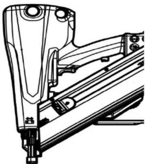
natural_image
Technical line drawing of a mechanical assembly with no visible text or symbolsnatural_image
Technical line drawing of a mechanical device with labeled component (2), showing internal components and assembly lines without any readable text or symbols.natural_image
Technical line drawing of a car interior showing engine compartment and wiring (no text or symbols)natural_image
Technical line drawing of a mechanical device with no visible text or symbolsnatural_image
Technical line drawing of a mechanical assembly with no visible text or symbolsnatural_image
Technical line drawing of a mechanical assembly with gears and housing (no text or symbols)Premere su "T" (1):
Scatto singolo
natural_image
Abstract black-and-white geometric pattern with arrow and triangle shapes (no text or symbols)natural_image
Two symbolic icons: a left-side trash bin with a cross and a right-side recycling symbol (no text or labels)


- Original Operating Manual for Motor-Powered Hybrid Fastener Driver Tools
- Bedeutung
- V
- Information about the manual 4
- Safety 9
- Description 21
- Before operation....30
- Operation 46
- After operation....56
- Transport and storage 58
- Cleaning and maintenance....62
- Eliminating malfunctions....65
- Ordering accessories....70
- Technical data....71
- Disposing of the fastener driving tool....74
- Manufacturer's address 75
- Warranty 76
- Index 77
- Information about the manual
- Integral part of the fastener driving tool
- Other applicable documents
- Design features of the text
- Design features of warning notices
- DANGER
- WARNING
- CAUTION
- ENVIRONMENTAL PROTECTION
- Design features of notices to material damage
- Definitions related to the tool
- Definition of the tool sides
- Safety
- Proper use
- Observing safety requirements
- Improper use
- Consequences of improper usage
- Safety notices
- General power tool safety warnings
- Work area safety
- Electrical safety
- Personal safety
- Power tool use and care
- Battery tool use and care
- Service
- Safety instructions for fastener driving tools
- Preventing explosion hazards
- Preventing serious or fatal injuries
- Preventing risks of injury
- Preventing material damage
- Personnel qualifications
- Safety devices
- Triggering safety device
- Blank safety device
- Information signs on the fastener driving tool
- Mandatory sign
- Meaning
- Pictograms
- Personal protective equipment
- Description
- Scope of delivery
- Tools with additional "SET"
- Tools with additional "SET4"
- Tools with additional "LM"
- Tools without addition
- Information on the rating plate
- Overview of the tool
- Overview of magazine
- Left side of the tool
- Right side of the tool
- Task and function
- Task
- Functional principle
- Single triggering with safety follow-up
- Contact triggering with automatic reset
- Control panel
- Display of operating states
- Before operation
- Unpacking the fastener driving tool
- Checking the condition
- Checking the external condition
- Checking the triggering safety device
- Filling with compressed air
- Important information about compressed air cartridges
- Note as well:
- Unscrewing the protective plug
- Using a compressed air cartridge
- Screwing in the compressed air cartridge
- Screwing in the protective plug
- Checking the operating pressure
- Fastening and removing the magazine
- Fastening the magazine
- Removing the magazine
- Loading and emptying the magazine
- Loading the magazine
- Emptying the magazine
- Attaching and removing rechargeable batteries
- Turning on the tool
- Checking the function
- Operation
- Selecting triggering process
- Single triggering
- Adjusting the insertion depth
- Checking the insertion depth
- Using imprint protection
- Driving in nails
- Triggering the fastener driving tool one time
- Triggering the fastener driving tool repeatedly
- Reloading nails
- Setting down the fastener driving tool
- Using the crossbar hook
- Venting the fastener driving tool
- After operation
- Turning off the tool
- Removing the rechargeable battery
- Transport and storage
- Packing the fastener driving tool
- Transporting the fastener driving tool
- Short distances
- Long distances
- Transporting the fastener driving tool over short distances
- Transporting the fastener driving tool over long distances
- Storing the fastener driving tool
- Cleaning and maintenance
- Cleaning
- Removing dirt and foreign objects
- Parts of the tool to keep clean
- Procedure
- Cleaning the housing and outer surfaces
- Maintenance
- Eliminating malfunctions
- ATTENTION!
- Rectifying malfunctions in transport to the shot channel
- Eliminating other malfunctions
- Ordering accessories
- Available accessories
- Information about ordering nails
- Technical data
- Battery and batter charging station
- Emission values
- Wear ear protectors!
- Disposing of the fastener driving tool
- Manufacturer's address
- PREBENA
- Warranty certificate
- Index
- A
- B
- C
- D
- E
- F
- H
- |
- K
- L
- M
- N
- 0
- P
- R
- S
- T
- U
- W
- Tabla de contenido
- Significado
- Instructions relatives au manuel....4
- Signification
- Procédure
- Encomendar acessórios....70
- Procedimento
- Encomendar acessórios
- Activeringsbeveiliging
- Betekenis
- Significato
Brand : Prebena
Model : PKT-8RKP100
Category : Stapler