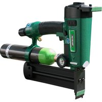
PKT-2-J50SD-SVN - Stapler Prebena - Free user manual and instructions
Find the device manual for free PKT-2-J50SD-SVN Prebena in PDF.


| Product type | Pneumatic stapler (driving device) |
| Brand | Prebena |
| Model | PKT-2-J50SD-SVN |
| Dimensions (without cartridge) | 319 × 71 × 272,5 mm |
| Dimensions (with cartridge) | 365,5 × 71 × 272,5 mm |
| Weight (without cartridge) | 2,15 kg |
| Weight (with cartridge) | 2,95 kg |
| Power supply | Compressed air cartridge KT-1000 (300 bar) or compressor via adapter |
| Operating pressure | 3,5 – 10 bar (max. 10 bar) |
| Air consumption | Approximately 0.2 L per nailing at 6 bar |
| Magazine capacity | Head nails type J, lengths 16 to 50 mm, wire gauge 1.05 × 1.25 mm |
| Trigger modes | Single trigger (T) or bump trigger (TTT) |
| Safety devices | Anti-trigger safety, dry-fire lockout, safety valves (20 bar and 11 bar) |
| Nailing depth adjustment | By adjustment wheel on the anti-trigger safety and by operating pressure |
| Exhaust air outlet | Adjustable 360° |
| Operating temperature range | -5 to +45 °C |
| Maintenance | Lubrication with PREBENA special oil, cleaning with dry cloth or soapy water |
| Repairability | Repairs only by the manufacturer or its authorized service center |
| Warranty | 1 year from date of purchase |
| Manufacturer | PREBENA WILFRIED BORNEMANN GMBH & CO. KG |
Frequently Asked Questions - PKT-2-J50SD-SVN Prebena
User questions about PKT-2-J50SD-SVN Prebena
0 question about this device. Answer the ones you know or ask your own.
Ask a new question about this device
Download the instructions for your Stapler in PDF format for free! Find your manual PKT-2-J50SD-SVN - Prebena and take your electronic device back in hand. On this page are published all the documents necessary for the use of your device. PKT-2-J50SD-SVN by Prebena.
USER MANUAL PKT-2-J50SD-SVN Prebena
GEFAHR
WARNING
VORSICHT

WARNUNG
WARNING
WARNING

WARNUNG

WARNUNG
WARNING
WARNING
VORSICHT
WARNING
WARNING
! WARNING
WARNING
VORSICHT
Magazin schließen

WARNUNG
WARNING
WARNING
WARNING
WARNING

WARNUNG
WARNING

WARNUNG
! WARNING

WARNUNG
This operating manual helps you in the
- intended,
- safe and
- effective
use of the PKT-2-J50 SD Pneumatic Tool, referred to in this operating manual simply as 'tool'.
We assume that every user of the tool is familiar with the use of pneumatic equipment and the materials employed. Persons without this know-how must be instructed in the use of the tool by an experienced user.
This operating manual is intended for the following persons:
- Persons who operate this tool,
- Persons who clean this tool, or
- Persons who dispose of this tool.
Each of these persons must have been familiarised with and understood the content of this operating manual.
This operating manual forms an integral part of the product. Always store the operating manual together with the tool. Pass on the operating manual if you resell the tool or pass it on to other persons in any other way.
Table of Contents
Layout Features....5
General layout features 5
Features of the danger warnings....6
Features of the warnings on material damage or environmental pollution 6
Safety 7
Intended use....7
Unauthorised use 7
Avoid risk of fatal injuries....8
Avoid explosion hazards 8
Avoid injury risks....8
Avoid damage to the tool....9
Description....10
Tool overview and scope of supply 10
Tool overview and scope of supply 11
Function....12
Product features 12
Safety devices .... 13
Accessories 14
Data on the rating plate....15
Preparing the tool....16
Unpacking the tool....16
Check condition....17
Connect tool to compressed air supply 18
Open magazine 26
Loading fasteners....27
Close the magazine....28
Adjusting the vent....28
Use with a weight balancer 29
Check function....30
Using the tool....31
Select firing setting. 31
Set nailing depth....33
Regulate working pressure....33
Driving in fasteners....36
Reload magazine (empty firing protection device) 39
After use 40
Disconnect the compressed air supply....40
Empty magazine....41
Transporting and storing the tool....42
Packing 42
Transporting....43
Storage 44
Servicing the tool....45
Cleaning housing and outer surfaces 45
Oiling the tool....46
Lubricate compressed air cartridge 47
Filling the compressed air cartridge ....47
Reordering compressed air cartridges ....47
Malfunctions....48
Remove jammed fasteners....48
Other malfunctions 49
Troubleshooting chart....49
Ordering accessories....53
Re-ordering fasteners....53
Reordering compressed air cartridges ....54
Ordering further accessories 55
Disposal of tool....56
Technical data....57
Tool PKT-2-J50 SD 57
Compressed air cartridge KT-1000 57
Manufacturer's address 58
Guarantee 59
Index......60
Layout Features
General layout features
Various elements in the operating manual are marked with specific layout features. This allows you to easily distinguish whether it is normal text,
- lists or
▶ work steps
that you are reading.

Tips contain additional information, such as for example special instructions for effective use of the tool.
Features of the danger warnings
All danger warnings in this operating manual have the same form. On the left you will find a symbol indicating the type of danger. To the right of this you will see a further symbol and a signal word indicating the severity of the danger. Under that you will find a description of the source of danger and instructions on how to avoid this danger.

DANGER
Warnings with the word DANGER indicate hazards with an immediate impending risk of serious or even fatal injuries.

WARNING
Warnings with the word WARNING warn of hazards that can lead to potentially serious or even fatal injuries.

CAUTION
Warnings with the word CAUTION warn of hazards that can lead to potentially slight to moderate injuries.
Features of the warnings on material damage or environmental pollution
CAUTION
These warnings warn of hazards that can lead to material damage or environmental pollution.
Safety
Observe and follow all the warnings and instructions in this operating manual and on the tool when using the tool. The spare parts list supplied with the tool forms an integral part of this operating manual.
Intended use
The tool is used for driving upset head nails ("brads") into wood. Use of the tool with other materials is only permitted after consultation with the manufacturer. The intended use also includes compliance with the accident prevent regulations and the statutory regulations and standards in force at the place of use. Use in any other way is not considered an intended use and can result in material damage or even personal injury.
Unauthorised use
An unauthorised use constitutes in particular operation
- by persons without the necessary know-how in the use of tools and the materials used,
• with the safety device bypassed, - of tools modified without the authorisation of the manufacturer,
- with accessories other than those stipulated in this operating manual,
- connected to compressed air sources not indicated in this operating manual,
-
in the trigger position "repeat firing"
-
for work requiring movements over scaffolds, stairs, ladders or ladder-like constructions,
- for closing boxes or crates or for the attachment of transport locks.
PREBENA WILFRIED BORNEMANN GMBH & CO. KG accepts no liability for any damage resulting from any such unauthorised use.
Avoid risk of fatal injuries
- Never direct the tool at people, animals or parts of their body.
- Only actuate the tool when the tool nose is pressed against the workpiece.
- Do not allow children to play with packaging films - risk of suffocation.
- Ensure that the fasteners are not driven into power cables.
Avoid explosion hazards
- Do not use the tool in areas with an explosion hazard.
- Never operate the tool with oxygen or other explosive gases or gas mixtures.
- Do not expose the compressed air cartridge to temperatures over 100° C.
Avoid injury risks
- Store the tool out of the reach of children and other unauthorised persons.
- Always disconnect the tool from the compressed air supply before transporting.
- Wear protective goggles, ear protectors and sturdy working clothes when working with the tool.
- Hold the tool in such a way that you cannot be injured by a possible recoil.
- Use the tool when you are standing with a firm footing.
Avoid damage to the tool
- Never open the tool. Always leave repairs to qualified personnel.
- Do not use the tool if it has been dropped or is damaged. Have it inspected by qualified personnel before putting it into use again.
- Do not connect the tool to a compressed air supply where the maximum working pressure of 10 bar may be exceeded.
- Attach permanently installed tools only to securely anchored holders. The tool must not be able to twist or slip. The holder must not damaged the tool and/or its accessories.
Description
Tool overview and scope of supply
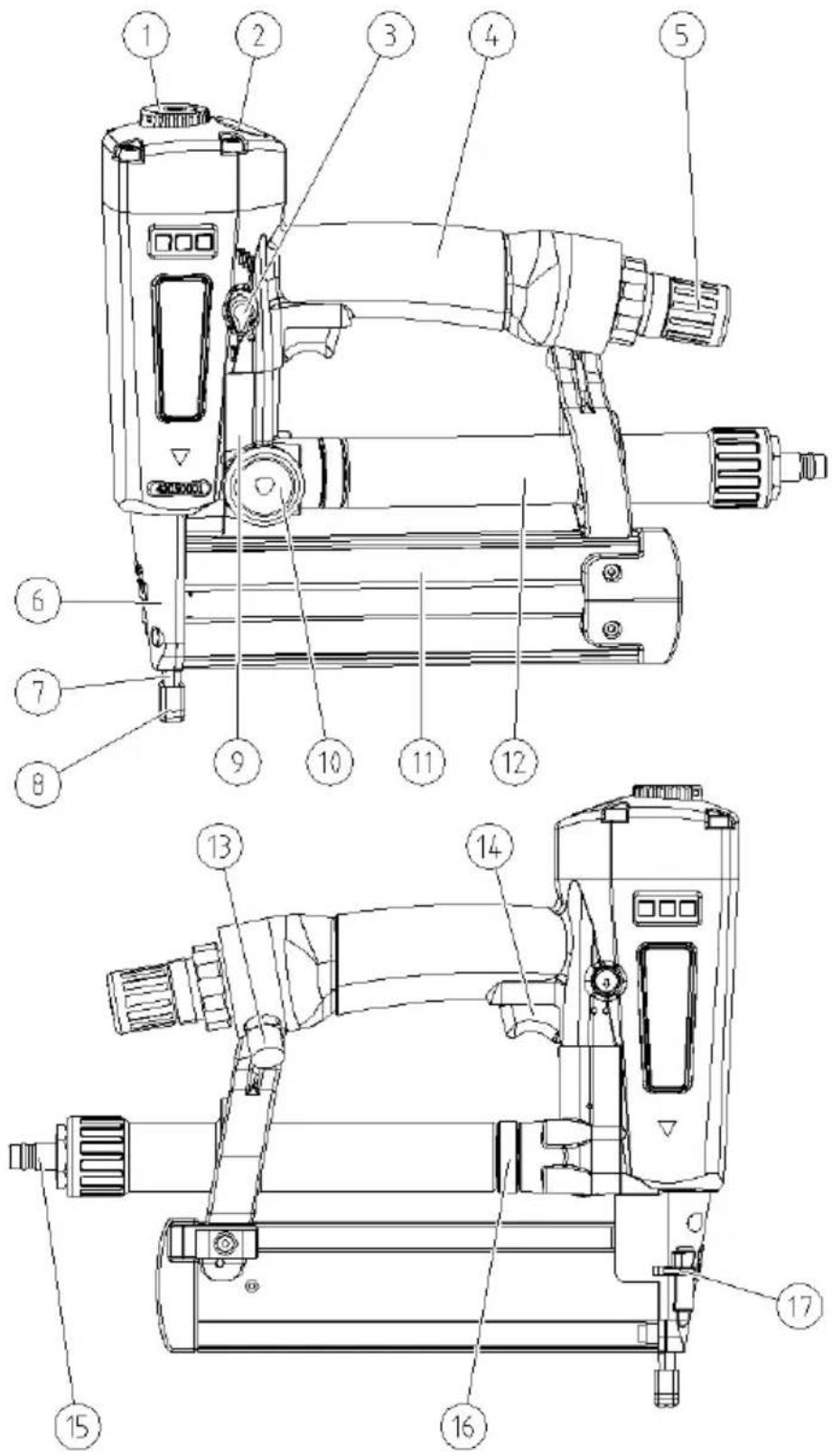
Tool overview and scope of supply
| No. | Explanation |
| 1 | Adjustable 360° air outlet |
| 2 | Pressure gauge for the tool working pressure |
| 3 | Selector switch for the trigger setting |
| 4 | Ergonomic handle with hand guard |
| 5 | Regulator for the working pressure |
| 6 | Cover plate |
| 7 | Tool nose with trigger lock |
| 8 | Rubber foot to protect the workpiece (impression protection) |
| 9 | Safety valve for operation with the compressed air cartridge (opens at 20 bar) |
| 10 | Pressure gauge for the pressure of the compressed air cartridge (filling level indicator) |
| 11 | Magazine for brads |
| 12 | Adapter for operation with pressure hose |
| 13 | Safety valve for the working pressure (opens at 11 bar) |
| 14 | Trigger lever |
| 15 | Connection for the pressure hose |
| 16 | Connection for the compressed air cartridge and adapter for connection of the pressure hose |
| 17 | Adjustment wheel for the firing protection device (setting of the nailing depth) |
| - | Compressed air cartridge KT-1000 (not illustrated) |
| - | Allen key (size 2.5, not illustrated) |
| - | Plastic transport case (not illustrated) |
| - | Declaration of conformity (not illustrated) |
| - | Operating manual (not illustrated) |
Function
The tool drives PREBENA brads individually into a piece of wood by means of compressed air. The compressed air supply can come from a compressed air cartridge (KT-1000) attached to the tool or from a PREBENA compressor via an adapter. Excessive pressure is relieved by means of pressure relief valves.
You can adjust the nailing depth by regulating the air pressure or with the adjusting wheel for the firing protection device.
Product features
The tool has the following features:
- Operation either with compressed air cartridge or on a compressed air system,
- Firing protection device,
- Single or bump firing,
• Empty firing protection device,
• Magazine with side loading system, - Adjustable 360° air outlet,
- Rubber foot to protect the workpiece (impression protection),
- Filling level indicator for compressed air cartridge,
- Driving force variable via adjustable working pressure,
- Pressure gauge for working pressure and
- Setting of the nailing depth via adjustment wheel for the firing protection device.
Safety devices
Firing protection
The tool is equipped with a firing protection device on the tool nose. The trigger is only enabled when the firing protection device is depressed.

WARNING
Danger of very serious injuries if the tool is operated with defective or by-passed firing protection device.
▶ Use the tool only with a fully functional firing protection device.
▶ Fire the tool only when the tool nose is pressed firmly against the material.
Empty firing protection device
The tool is equipped with an empty firing protection device. The empty firing protection device blocks the firing protection device when the fastener magazine is empty.
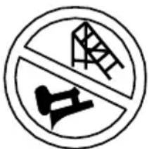
Warning signs on the tool
The following applications are not permitted with the trigger setting "repeat firing":
- Work requiring movements over scaffolds, stairs, ladders or ladder-like constructions, and
- Use for closing boxes or crates and for the attachment of transport locks.
The corresponding warning symbol (see below) is attached to the front side of the tool.
- The rating plate
- The inverted triangle standing on its tip. (This triangle indicates that this tool may only be operated with a fully functional firing protection device.)
Accessories
The following accessories are available for the tool:
- Compressed air cartridge KT-1000,
- Five compressed air cartridges KT-1000 in systainer (not included in scope of supply),
- Compressor for compressed air cartridge PKT-FILLMASTER 350 DF (not included in scope of supply),
- Compressors for the compressed air supply (not included in scope of supply),
- Spiral hose with 9 mm inside diameter and 4 m working length (not included in scope of supply),
- Compressed air hose set (not included in scope of supply),
-
Hose reel (not included in scope of supply),
-
Hanger loop (not included in scope of supply),
- Brads of Type J (see section "Ordering accessories" on page 53).
- PREBENA Special Nailer Oil (not included in scope of supply).
The order numbers can be found in section "Ordering accessories" from page 53
Data on the rating plate
The rating plate is attached to the magazine. It contains the following information:
- The company name and full address of the manufacturer
- The designation of the machine (DN Type = pneumatic tool)
- Type designation of the tool
- Type designation of the fasteners that may be used
- The maximum admissible working pressure
- The CE symbol (the product conforms to the standards listed in the Declaration of Conformity supplied)
- The GS symbol (the product has passed a safety test in accordance with the German Equipment and Product Safety Act)
- The inverted triangle (this triangle indicates that this tool may only be operated with fully functional firing protection device)
• The year of manufacture
Preparing the tool
Unpacking the tool
▶ Remove the tool from the packaging.
▶ Remove all packaging materials, such as plastic films, filler material and the cardboard box.


WARNING
Do not allow children to play with plastic packaging films. Risk of suffocation!
▶ Do not allow children to play with plastic packaging films.
▶ Store the packaging materials out of the reach of children.
▶ Save the packaging material for later use.
▶ Keep the transport case for the transport of the tool.

The tool may only be transported in the transport case.
Check condition


WARNING
Risk of injury when using a damaged tool or if accessories are not correctly attached.
▶ Check the condition of the tool before every use.
▶ Always ensure that the tool is in a safe working condition.
▶ Check in particular the following points:
- All parts of the tool and all accessories must be securely attached.
- The safety devices must not be blocked or otherwise impaired in their function.
- The spring of the firing protection device must not be damaged.
- No parts of the tool or the accessories may show visible signs of damage, such as scratches or dents.
- The air hose must be undamaged.
i Scratches in the paintwork of the housing or magazine are not "damage".
▶ Do not connect a damaged tool to a compressed air supply.
▶ Have a damaged tool repaired by qualified personnel before putting it into operation.
Connect tool to compressed air supply
You can connect the tool to a compressed air system or to a compressed air cartridge.
If you connect the tool to a compressed air system by means of an adapter, you can carry out frequent brad driving operations efficiently in the same place. In addition you can supply oil to the tool via the compressed air system.
If you connect the tool to a compressed air cartridge, you are independent of a stationary installation.
The admissible working pressure of the tool is 10 bar. If the admissible working pressure is exceeded, the pointer of the pressure gauge for the working pressure moves into the red range.
This can occur under the following conditions:
- If both safety valves are defective,
- If you have set the working pressure too high (see page 33), or
- If you have connected the tool to a compressed air system with excessively high pressure or to an unsuitable compressed air cartridge.


WARNING
Risk of explosion if the maximum working pressure is exceeded.
▶ In this case immediately disconnect the compressed air supply from the tool (see page 40).
Attach compressed air cartridge


WARNING
Risk of injury from unsuitable compressed air cartridges.
▶ Use only original PREBENA compressed air cartridges of Type KT-1000.
▶ Operate the tool only when it is in a safe working condition.
Important notes for the handling of compressed air cartridges
- Use only original PREBENA KT-1000 compressed air cartridges for the tools described here.
- Use the KT-1000 compressed air cartridge only to supply compressed air to the tools described in this manual.
- Keep the valve of the compressed air cartridge and the connection on the tool clean and protect from damage. Remove any soiling before starting work. Severe soiling may only be removed by the manufacturer.
- Lubricate the thread of the valve on the compressed air cartridge with universal grease before every use.
- Do not use defective or damaged compressed air cartridges. Have defective or damaged compressed air cartridges replaced by your dealer.
- The labelling on the compressed air cartridge must not be removed or made illegible.
- Transport and store the compressed air cartridges only in the original packaging or in the transport case of the tool.
- The compressed air cartridge must not be transported while connected to the tool. Remove the compressed air cartridge from the tool after every use.
Connecting the compressed air cartridge
▶ Check the condition of the tool (see page 17).
▶ Remove the protective cap from the connecting thread of the compressed air cartridge.
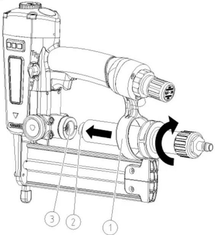
▶ Check the fitting (3) and the connecting thread of the compressed air cartridge (2) for foreign matter and soiling.
▶ Clean the fitting and connecting thread, if necessary.
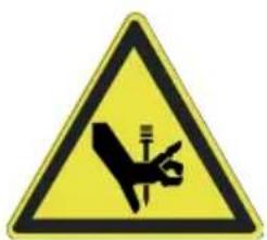
WARNING
Inadvertent firing during connection to the compressed air supply can result in serious or even fatal injuries.
▶ Never direct the tool towards yourself, other people or animals.
▶ Empty the magazine before connecting (see page 41).
▶ Push the compressed air cartridge into the holder (1).
▶ Screw the thread of the compressed air cartridge (2) finger-tight into the thread of fitting (3).

The pressure gauge at the connector for the compressed air cartridge (4) now shows the pressure currently prevailing in the cartridge. The tool is ready for operation when the pointer of the pressure gauge is in the green range of the scale.
The pressure gauge for the working pressure (5) displays the current working pressure. The tool is ready for operation when the pointer of the pressure gauge for the working pressure (5) indicates between 3.5 and 10 bar.
▶ Adjust the working pressure (see page 33), if necessary.
If you use an unsuitable compressed air cartridge, set the working pressure too high or if both safety valves are defective, the pressure in this cartridge can exceed the maximum admissible working pressure of the tool. In this case the pointer of the pressure gauge for the working pressure (5) is in the red range of the scale.

WARNING
Risk of explosion if the maximum working pressure is exceeded.
▶ In this case immediately disconnect the compressed air cartridge from the tool (see page 40).
When the pointer of the pressure gauge at the connector for the compressed air cartridge (4) is in the red zone of the scale, the pressure in the compressed air cartridge is no longer sufficient for operation of the tool.
▶ In this case replace the compressed air cartridge with a full compressed air cartridge.
You can refill the compressed air cartridge using the PKT-FILLMASTER 350 DF compressor available as an accessory. You can also purchase a full compressed air cartridge in exchange for an empty cartridge from your dealer.
Connecting the compressed air hose
The tool can be connected to a compressor or a compressed air system.
Operation with a compressor or compressed air system is only permitted under the following conditions:
- The working pressure of the compressor or compressed air system must not be more than 10% above the maximum working pressure of the tool of 10 bar.
- If the compressed air system has a higher working pressure, a pressure control valve (pressure reducer) with downline pressure relief valve must be installed in the compressed air line.
- The compressed air must be filtered, dry and oiled with PREBENA special nailer oil.
- An air conditioner must be installed on the coupling side of the outlet ports for the compressed air line to the tool. This should comprise
- a filter,
- a water trap and
- an oiler.
- If no oiler is installed, the length of the air line to the tool must not exceed max. 10 metres. Otherwise pour three to five drops of PREBENA special nailer oil directly into the air inlet port of the tool every day before starting work.
- The compressed air system must be able to maintain the working pressure even with the desired air consumption.
- The diameter of the fixed air lines must be at least 19 mm.
- The connection for the tool must be fitted with a quick coupler with NW 7.2 and with an inside diameter of at least 6.5 mm.

CAUTION
Operation on compressed air systems not satisfying the preconditions described above can result in damage to the tool.
▶ Operate the tool only on suitable compressed air systems (see page 22).
▶ Operate the tool only when it is in a safe working condition (see page 17).
▶ Check the condition of the tool (see page 17).
▶ Check the fitting (3) and the connecting thread of the adapter (2) for foreign matter and soiling.
▶ Clean the fitting and connecting thread, if necessary.
▶ Push the adapter into the holder (1).
▶ Screw the thread of the adapter (2) finger-tight into the thread of fitting (3).
▶ Set the working pressure at the pressure regulator of the compressor to max. 10 bar.
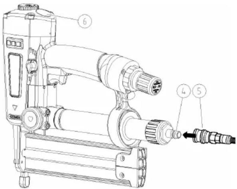
▶ Check the connection for the pressure hose (4) and the quick coupler (2) of the pressure hose for foreign matter and soiling and clean, if necessary.
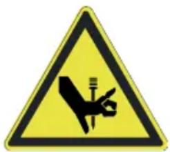
WARNING
Inadvertent firing during connection to the compressed air supply can result in serious or even fatal injuries.
▶ Never direct the tool towards yourself, other people or animals.
▶ Empty the magazine before connecting (see page 41).

WARNING
Damaged hoses can burst and result in injuries.
▶ Inspect the compressed air system and tool for damage before connection.
▶ Connect the tool only to a fully functional compressed air system.
CAUTION
Damaged hoses can burst and and cause material damage due to the escaping compressed air.
▶ Inspect the compressed air system and tool for damage before connection.
▶ Connect the tool only to a fully functional compressed air system.
▶ Push the quick coupler (1) of the compressed air hose (5) onto the fitting (4) until it engages tangibly and audibly.
▶ Check the indication on the pressure gauge for the working pressure (6).
The pressure gauge for the working pressure (6) displays the current working pressure. The tool is ready for operation when the pointer of the pressure gauge for the working pressure (6) indicates between 3.5 and 10 bar.
▶ Adjust the working pressure (see page 33), if necessary.
The maximum admissible working pressure of the tool is 10 bar. If the compressed air system has an excessively high pressure, you have set the working pressure too high or the safety valve for the working pressure is defective, the maximum working pressure may be exceeded. In this case the pointer of the pressure gauge for the working pressure (7) is in the red range of the scale.

WARNING
Risk of explosion if the maximum working pressure is exceeded.
▶ In this case immediately disconnect the compressed air hose from the tool (see page 40).
Open magazine
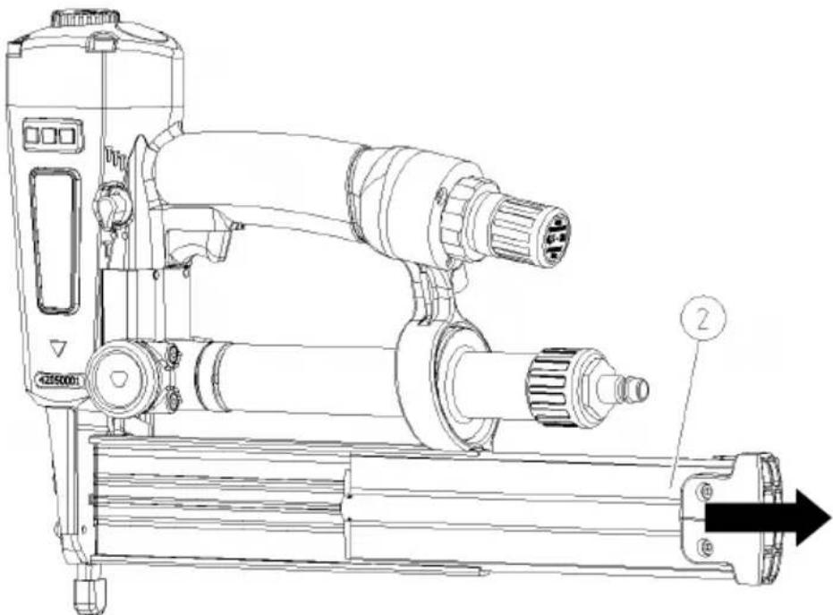
▶ To open the magazine, press the magazine catch (1) to the left in the direction of the arrow.
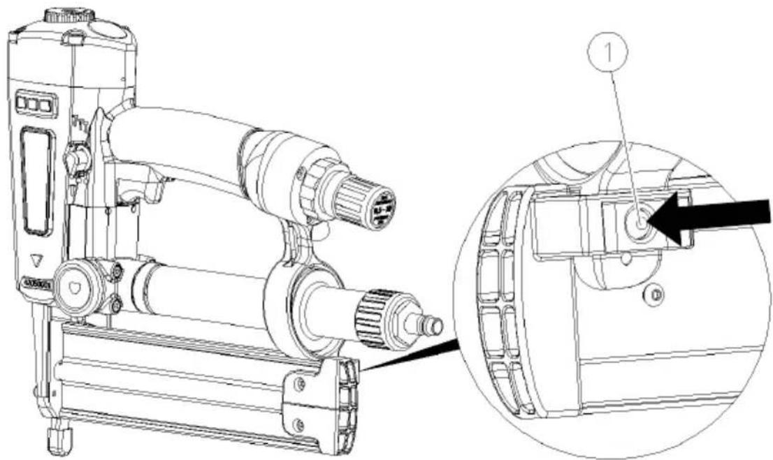
▶ Pull the lateral slide (2) out to the right.
Loading fasteners

WARNING
Inadvertent firing during filling of the magazine can result in serious or even fatal injuries.
▶ Never direct the tool towards yourself, other people or animals.

CAUTION
Incorrect fasteners can lead to injury, impair the proper function of the tool or damage the tool.
▶ Use only the PREBENA fasteners indicated in section "Ordering accessories" (see from page 53).
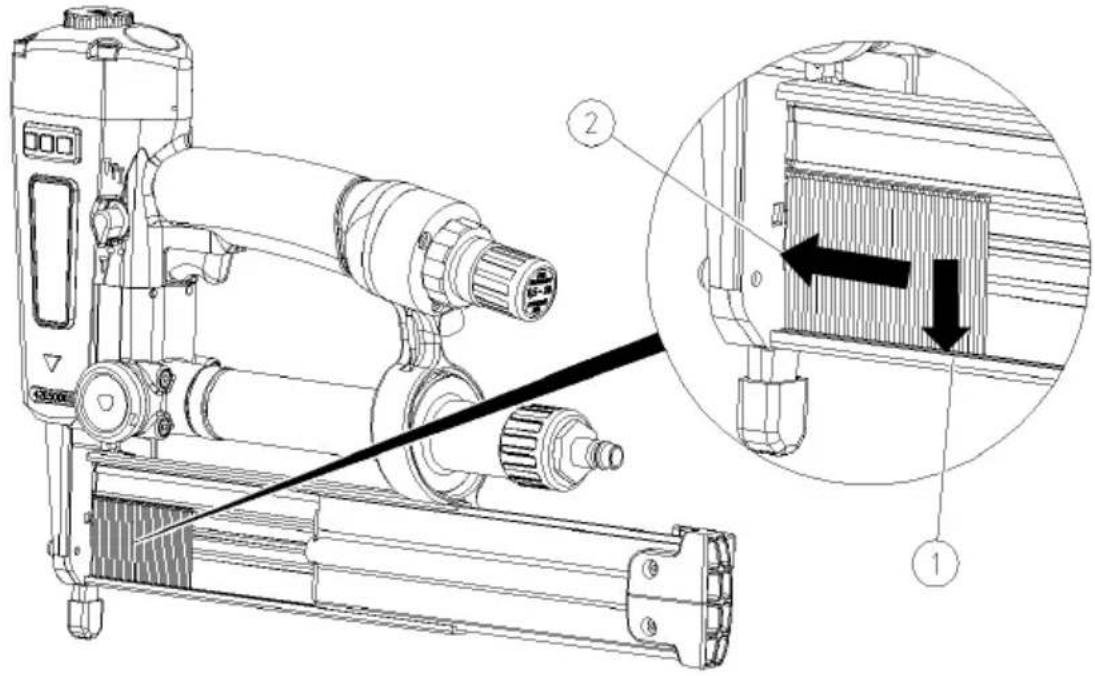
▶ Load the fasteners so that their tip is facing towards the bottom of the magazine (1).
▶ Push the fasteners as far as possible to the left into the loading section (2).
Close the magazine
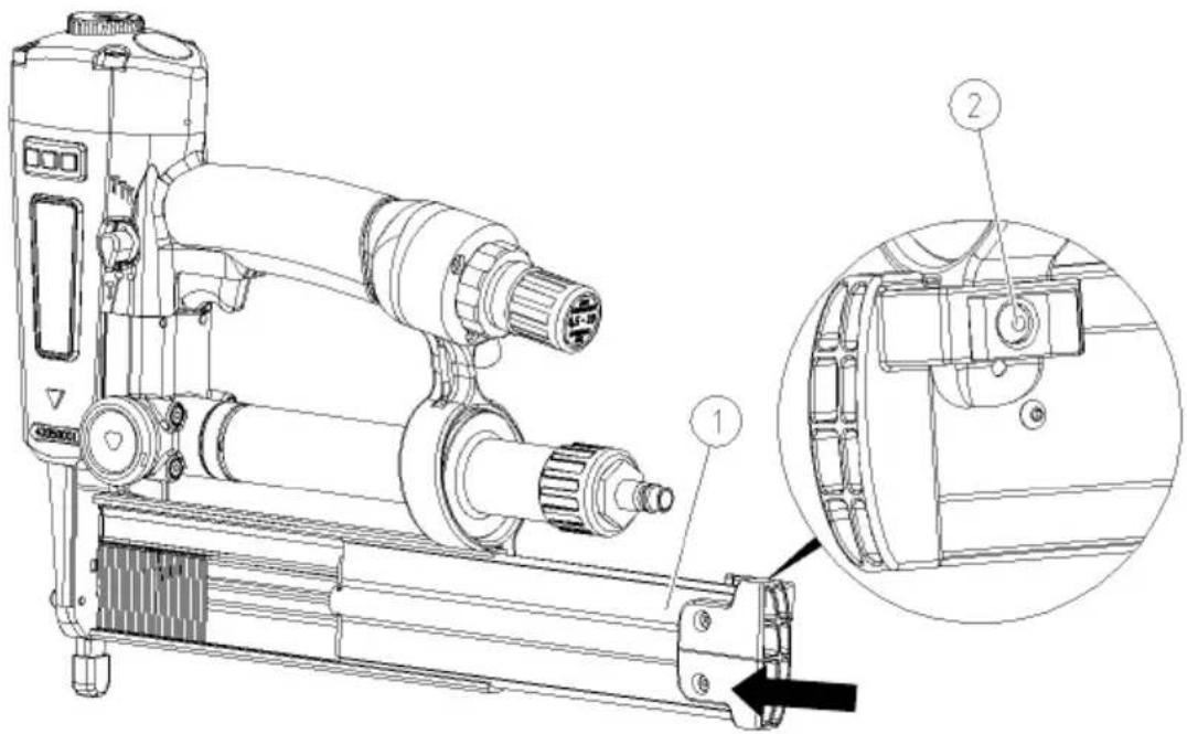
▶ To close the magazine, push the lateral slide (1) to the left until the magazine lock (2) engages.
Adjusting the vent
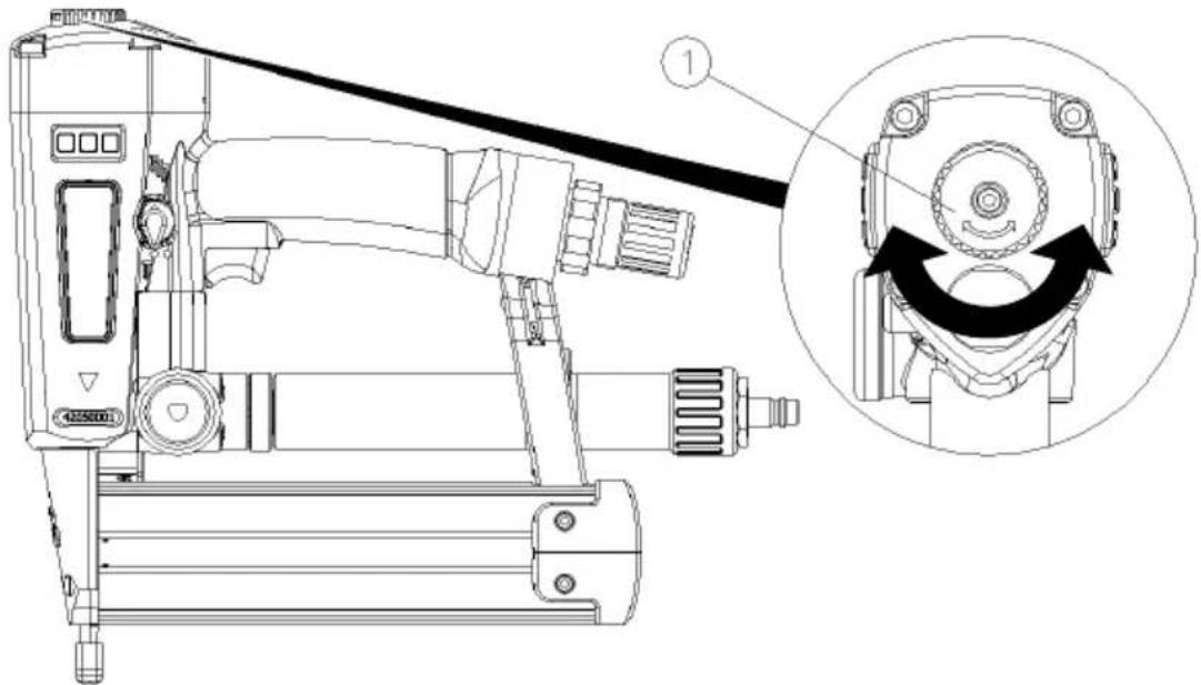
▶ To adjust the vent, turn the adjusting wheel (1) in the desired direction.
▶ Turn the vent so that the exhaust air is not directed at either yourself or other persons.
Use with a weight balancer
You can use the tool with a weight balancer. In order to attach the rope of the weight balancer to the tool, a hanger loop has to be attached to the housing head. Proceed as follows:
▶ Remove the compressed air cartridge or compressed air hose from the tool (see page 40).
▶ Empty the magazine (see page 41).
▶ Loosen and remove the two rear hex. socket head screws (1) on the housing head.
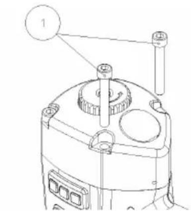
▶ Position the hanger loop (2) as illustrated below.
▶ Attach the hanger lop (2) with the hex. socket head screws (1).
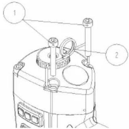
The hander loop is now ready for use.
▶ Check the condition of the tool (see page 17).
The hanger loop (Article No. ET 42008001) can be obtained as an accessory from PREBENA.
Check function
To ensure the proper function of the tool, proceed as follows:
CAUTION
▶ Observe the danger warnings in chapter "Safety" from page 7.
▶ Press the tool nose of the tool against a piece of wood at least ten centimetres thick.
▶ Fire the tool (see chapter "Driving in fasteners" from page 36).
▶ Check the following points:
- Firing occurs only when the firing safety device is depressed.
– Each time the tool is fired, a fastener must be driven into the piece of wood. - The exhaust air must not be discharged towards your face.
In order to obtain the desired nailing depth, adjust the working pressure or the setting of the adjusting wheel (see page 33), if necessary.
▶ Repeat these steps, if necessary.
The tool is now ready for operation.
Using the tool
Select firing setting.
The tool can be set for single firing or for repeat firing. With the repeat firing setting, the trigger does not have to be pressed every time. Every firing of the tool drives a nail into the material.
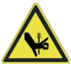
WARNING
Inadvertent firing while changing the firing setting can lead to serious or even fatal injuries.
▶ Never direct the tool towards yourself, other people or animals.
In particular, the trigger setting "repeat firing" must not be used for the following applications:
- For applications requiring movements with the tool over scaffolds, stairs, ladders or ladder-like constructions,
- For closing boxes or crates, and
- For the attachment of transport locks.
▶ For these applications, set the selector switch to "T" (single firing).
The black selector switch (1) for the firing setting is located to the left of the trigger.
To select the trigger setting, proceed as follows:
The firing setting is marked on the housing. Single firing is marked by "T", repeat firing by "TTT".
▶ Turn the selector switch (1) to the desired position until it engages noticeably.
The tip of the selector switch points towards the selected setting.
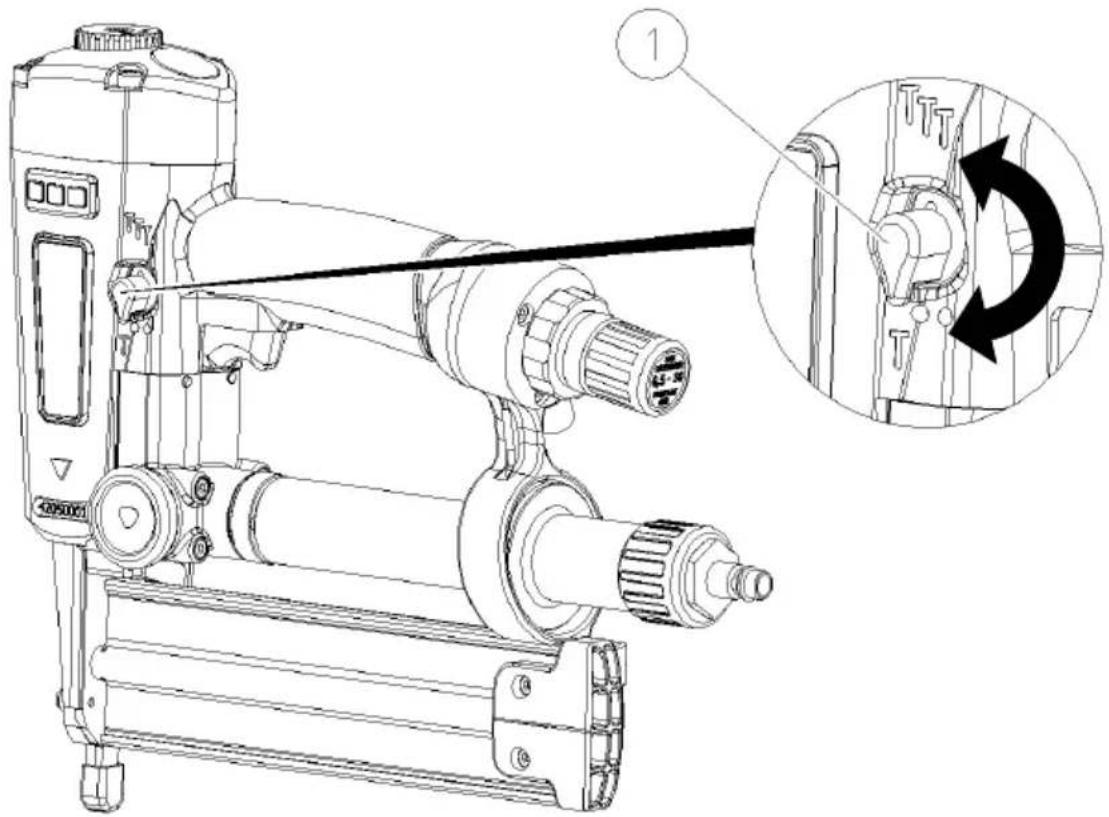
The firing setting is selected.
Set nailing depth
You can set the nailing depth of the fasteners into the wood by turning the adjusting wheel of the firing protection device and by regulating the working pressure.
Regulate working pressure
The nailing depth of the fastener into the wood can be set by adjusting the working pressure. With higher working pressure, the fasteners are driven in deeper, with lower working pressure less deeply.
Set the working pressure at the tool such that the desired nailing depth is just obtained. This offers the following advantages:
- You save energy (compressed air),
- You reduce the noise level, and
- You reduce the wear on the tool.
To adjust the working pressure at the tool, proceed as follows:
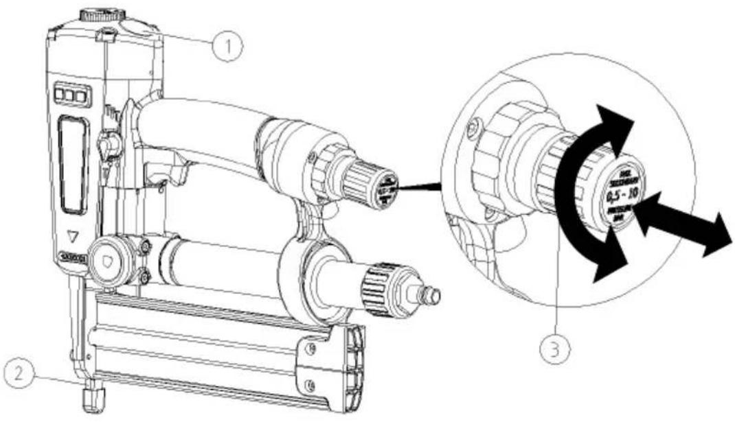
▶ Hold the tool so that you can easily read the pressure gauge for the working pressure (1) and the tool nose (2) is facing downwards.
▶ Pull the regulator for the working pressure (3) to the right away from the handle.
Then set the desired working pressure between 3.5 and 10 bar at the regulator for the working pressure (3) and the nailing depth as follows:
▶ To increase the working pressure and nailing depth, turn the regulator for the working pressure in clockwise direction.
▶ To reduce the working pressure and nailing depth, turn the regulator for the working pressure in anti-clockwise direction.
A quarter turn of the regulator for the working pressure changes the working pressure by roughly 0.5 bar.
▶ Observe the indication on the pressure gauge for the working pressure (1).
▶ Press the regulator for the working pressure (3) to the left against the handle until it engages audibly and tangibly.
The regulator for the working pressure is now locked.
The desired working pressure is now set.
When operating with a compressed air hose, you can set the working pressure at the tool only as high as the output pressure of the compressor.
Set nailing depth at adjustment wheel of firing protection device
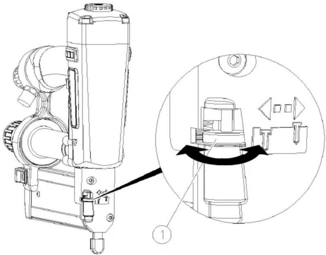
You can also set the nailing depth of the fasteners in the wood by turning the adjustment wheel of the firing protection device.
You will finding the following symbol on the cover of the tool:

▶ To reduce the nailing depth, turn the adjustment wheel (1) of the firing protection device in anti-clockwise direction.
▶ To increase the nailing depth, turn the adjustment wheel (1) of the firing protection device in clockwise direction.
Checking nailing depth
▶ Press the tool nose against a wooden test block with the same characteristics as the material to be nailed.
▶ Check the setting with a single firing against the test material (see page 37).
▶ Repeat these steps until the desired nailing depth is obtained.
Driving in fasteners

WARNING
Risk of injury due to electric shock.
▶ Ensure that no electric cables can be hit before firing the tool.
WARNING
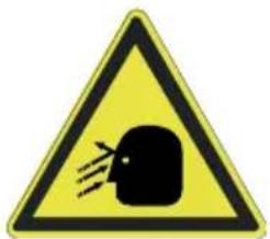
During operation, injuries to the eyes or other injuries are possible caused by flying splinters.
▶ Wear protective goggles and appropriate protective clothing during work.
▶ Observe the prevailing accident prevention regulations.

WARNING
Damage to your hearing is possible due to the loud working noise.
▶ Wear suitable ear protectors.
▶ Observe the prevailing noise protection regulations.
▶ Select the lowest possible working pressure.

WARNING
Risk of injury from slipping nails, nails driven in too deeply or from tool recoil.
▶ Use the tool only on wooden materials.
▶ Ensure that the nailing depth is not larger than the thickness of the wood.
▶ Press the tool firmly against the wood when firing.
A severe recoil occurs if fasteners are driven into excessively hard workpieces or into other fasteners. This can cause the tool to slip off the workpiece.
The nailing depth of the fasteners depends on the hardness and thickness of the wood, the depth setting and the set working pressure.
▶ Ensure that no other persons are standing behind the wooden block.
▶ Then check the function of the tool at low working pressure by firing once.
▶ Adjust the nailing depth and working pressure according to the hardness of the wood used.
The correct working pressure has been set when the desired nailing depth of the fasteners is obtained with the lowest possible pressure.
Fire tool once
To fire the tool once, proceed as follows:
▶ Set the selector switch to "T" (single firing) (see page 31).
▶ Position the tool nose of the tool against the wood and press the tool firmly against the wood.
▶ Press the trigger lever.
A fastener is driven into the wood.
▶ Release the trigger lever.
▶ Lift the tool off the wood.
▶ To drive in further fasteners, repeat these steps.
Fire tool repeatedly
The tool must not be used with the setting "repeat firing" in the following cases:
- For applications requiring movements with the tool over scaffolds, stairs, ladders or ladder-like constructions,
- For closing boxes or crates, and
- For the attachment of transport locks.
▶ For these applications, set the selector switch to "T" (single firing).
To fire the tool repeatedly, proceed as follows:
▶ Check the setting by firing once.
▶ Lift the tool off the wood.
▶ Adjust the desired nailing depth (see page 33), if necessary.
▶ Set the selector switch to "TTT" (repeat firing) (see page 31).
▶ Press the trigger lever.


WARNING
Risk of injury from recoil and unintentional firing.
▶ Press the tool firmly against the wood.
▶ Position the tool nose of the tool against the wood and press the tool briefly against the wood.
The fastener is driven in.
▶ To drive in further fasteners, hold the trigger lever depressed.
▶ Move the tool to the next desired nailing position.
▶ Press the tool against the wood.
The next fastener is driven in.
This process can be repeated as long as the trigger is held depressed and there are fasteners in the magazine.
Reload magazine (empty firing protection device)
The tool is equipped with an empty firing protection device. This prevents the tool being fired when there are no more fasteners in the magazine.
When the empty firing protection device has tripped, no further fasteners can be fired.
▶ Refill the magazine as described from page 26.
After use
After use or prior to prolonged stoppages in work, carry out the following steps.
Disconnect the compressed air supply
Remove compressed air cartridge
▶ Unscrew the compressed air cartridge from the thread of the fitting.
The compressed air contained in the tool escapes audibly.
▶ Pull the compressed air cartridge back out of the holder on the tool.
- Store the compressed air cartridge protected against blows and dropping in the transport case supplied.

You can refill the compressed air cartridge using the PKT-FILLMASTER 350 DF compressor available as an accessory. You can also purchase a full compressed air cartridge in exchange for an empty cartridge from your dealer.
Disconnect compressed air hose
▶ Pull the quick coupler of the compressed air hose away from the adapter.
The quick coupler is now released.
▶ Disconnect the compressed air hose from the connection on the adapter of the tool.
The compressed air contained in the tool escapes audibly.
▶ Unscrew the adapter from the thread of the fitting.
▶ Pull the adapter back out of the holder on the tool.
- Store the adapter protected against blows and dropping in the transport case supplied.
Empty magazine
Remove the unused fasteners from the magazine when you are no longer going to use the tool.
Proceed as follows:

WARNING
Inadvertent firing during emptying of the magazine can result in serious or even fatal injuries.
▶ Disconnect the tool from the compressed air supply (see page 40).
▶ Open the magazine (see page 26).
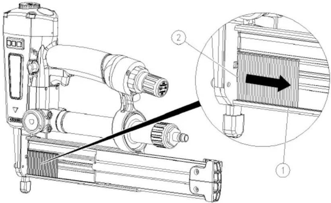
▶ Push the remaining fasteners in the magazine to the right out of the loading section (2).
▶ Remove the remaining fasteners from the magazine (1).
▶ Close the magazine (see page 28).
Transporting and storing the tool
Packing
Pack the tool before storage or before transporting over the following distances:
• Distances of more than 10 m
- Routes across insecure ground
- Routes requiring an unusual body posture.
Carry out the following preparatory steps:
▶ Disconnect the tool from the compressed air supply (see page 40).
▶ Allow the pressure to be completely relieved from the tool.
▶ Empty the magazine (see page 41).
▶ If necessary, clean the compressed air connections to remove any foreign matter and soiling.
▶ Place the tool, adapter and compressed air cartridge into the transport case as illustrated.
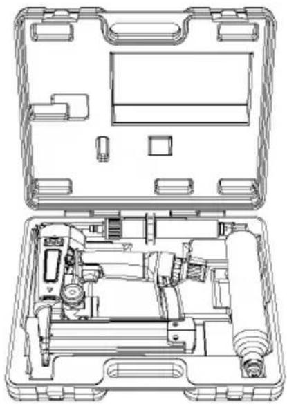
▶ Close the transport case and the latch for the lid.
Transporting
The method of transport differs, depending on whether you have to transport the tool over long or short distances.
Transport over short distances
Short distances are distances of not more than 10 metres.

WARNING
Inadvertent firing can result in serious or even fatal injuries.
▶ Always disconnect the tool from the compressed air supply before transport (see page 40).
▶ Carry the tool only at the handle.
▶ Do not touch the trigger lever during transport.
▶ Disconnect the tool from the pressure supply (see page 40).
CAUTION
Banging or dropping can result in damage to the tool.
▶ Do not drop the tool.
▶ Protect the tool to prevent it banging against any obstacles.
- Carry the tool at the handle with the tool nose facing towards the ground.
▶ Reconnect the compressed air supply only when you reach the new working location.
Transport over long distances
The following distances are regarded as "long distances" for the transport of the tool:
• Distances of more than 10 m,
- Routes across insecure ground
- Routes requiring an unusual body posture.
To transport the tool over long distances, proceed as follows:
▶ Pack the tool in the transport case supplied (see page 42).
- Carry the transport case at the handle to the desired working location.
▶ Set the transport case down only in a horizontal position with the lid facing upwards.
Storage
▶ Oil all metal parts of the tool thinly with PREBENA special nailer oil.
▶ Pack the tool in the transport case (see page 42).
- Store the tool at room temperature in a dry place protected from dust.
Servicing the tool
The tool may only be serviced by persons with the necessary know-how, abilities and experience. All work not described here must be carried out by the manufacturer's After-Sales Service or in the manufacturer's works.

WARNING
Inadvertent firing during servicing of the tool can result in serious or even fatal injuries.
▶ Disconnect the compressed air supply before carrying out service work on the tool (see page 40).
▶ Empty the magazine before carrying out service work (see page 41).
Cleaning housing and outer surfaces
CAUTION
Unsuitable cleaning agents can cause damage to the tool or the accessories.
▶ Use only a dry or slightly damp cloth or a cloth dampened with a mild soap solution.
Minor soiling
▶ Wipe off the housing of the tool with a dry cloth.
▶ Oil all metal parts of the tool thinly with PREBENA special nailer oil.
Severe soiling
▶ Wipe off the housing of the tool with a cloth dampened slightly with a mild soap solution.
▶ Then wipe off the housing with a cloth dampened slightly with tap water.
▶ Finally wipe the housing dry with a soft, dry cloth.
▶ Oil all metal parts of the tool thinly with PREBENA special nailer oil.
Oiling the tool
CAUTION
Insufficient lubrication or the use of the wrong lubricants can cause damage to the tool.
▶ Use only PREBENA special nailer oil.
If no oiler is installed and the length of the compressed air line to the tool is more than 10 metres, adequate lubrication is not assured. If you operate the tool only with compressed air cartridges, the tool cannot be sufficiently oiled via the compressed air.
In these two cases, pour two to five drops of PREBENA special nailer oil directly into the port for the compressed air source every day before starting work.
CAUTION
Danger of environmental pollution if the lubricating oil is spilled.
▶ Pick up spilled oil with a binder.
▶ Pick up bound oil with cloths.
▶ Dispose of the cloths in accordance with the statutory regulations in force at the place of use.
Lubricate compressed air cartridge
CAUTION
Insufficient lubrication or the use of the wrong lubricants can cause damage to the tool and the compressed air cartridge.
▶ Use only universal lubricating grease.
▶ Lubricate the thread of the valve on the compressed air cartridge with universal grease before every use.
Filling the compressed air cartridge
Empty KT-1000 compressed air cartridges may only be filled with the PKT-FILLMASTER 350 DF compressor available as an accessory.
▶ Observe the operating manual of the compressor.
Reordering compressed air cartridges
You can purchase full KT-1000 compressed air cartridges in exchange for empty cartridges from your dealer.
You can order the compressed air cartridges individually (KT-1000) or in the special transport container ("Systainer KT-1000-SY") with five compressed air cartridges (KT-1000).
Information on exchanging cartridges can also be found at www.kartuschen-tausch.de
Malfunctions


WARNING
Operation of a damaged or malfunctioning tool can result in serious or even fatal injuries.
▶ Always disconnect the tool immediately from the compressed air supply in the event of a malfunction (see page 40).
▶ Empty the magazine (see page 41).
▶ Use the tool again only when the malfunction has been remedied.
CAUTION
The tool may be damaged in the event of repairs by unauthorised persons.
▶ Ensure that repairs to the tool are only carried out by the manufacturer.
Remove jammed fasteners
The tool has a removable cover plate on the tool nose. Jammed or deformed fasteners can be removed from the tool nose via this cover.
To remove a jammed fastener, proceed as follows:
▶ Disconnect the tool from the compressed air supply (see page 40).
▶ Empty the magazine (see page 41).
▶ Loosen and remove the round-head screws of the cover plate using the Allen key contained in the scope of supply.
▶ Remove the cover plate (see pages 10 and 11 No. 8) from the tool.
▶ Remove the jammed or deformed fastener.
▶ Attach the cover plate again with the round-head screws.
▶ Fill the magazine as described from page 26.
▶ Connect the compressed air supply (see page 18).
▶ Check the function of the tool (see page 30).
Should you be unable to remedy the malfunction, contact your dealer or the manufacturer (see page 58).
Other malfunctions
If malfunctions occur in the tool that cannot be remedied by cleaning and oiling, please contact PREBENA Service.
▶ Do not carry out repairs to the tool yourself.
▶ Ensure that all malfunctions in the tool are remedied by PREBENA Service.
Troubleshooting chart
The following chart shows possible malfunctions and the necessary measures.
| Symptom | Possible cause | Remedy |
| Tool loses air. | The attachment screws are loose. | ▸ Tighten attachment screws. |
| A seal is defective. | ▸ Contact Service (see page 58). | |
| Working pressure too high (pointer of pressure gauge over 10 bar). | Working pressure set too high or tool damaged. | ▸ Reduce working pressure (see page 33).If the problem continues to exist:▸ Disconnect the tool immediately from the compressed air supply (see page 40).Contact Service (see page 58). |
| Working pressure too high (pointer of pressure gauge over 10 bar). | Pressure reduction valve or safety valve defective. | ▸ Disconnect the tool immediately from the compressed air supply (see page 40).▸ Contact Service (see page 58). |
| Working pressure too high (air escaping audibly at the safety valve for operation with compressed air cartridge). | Pressure reducer defective. | ▸ Disconnect cartridge from tool.▸ Contact Service (see page 58). |
| Working pressure too high (air escaping audibly at safety valve for the working pressure). | Working pressure set too high or tool damaged. | ▸ Reduce working pressure (see page 33).If the problem continues to exist:▸ Disconnect the tool immediately from the compressed air supply (see page 40).▸ Contact Service (see page 58). |
| Fasteners are not driven in completely. | Working pressure too low. | ▸ Increase working pressure (see page 33). |
| Pressure in compressed air cartridge too low. | ▸ Replace compressed air cartridge (see page 19). | |
| Adjustment wheel of firing protection device set wrongly. | ▸ Adjust firing protection device (see page 34). | |
| The driver tip of the tool is worn. | ▸ Contact Service (see page 58). | |
| Firing not possible. | Working pressure too low. | ▸ Increase working pressure of compressed air system to maximum admissible working pressure.▸ Increase working pressure at tool to maximum admissible working pressure.▸ Then fire several times.▸ If the tool fires, set the desired working pressure (see page 33). |
| ▸ Replace compressed air cartridge (see page 19). | ||
| The moving parts are stuck with lubricant after prolonged storage. | ▸ Clean the tool and apply fresh oil (see page 46).▸ Set the maximum working pressure.▸ Then fire several times.▸ If the tool fires, set the desired working pressure (see page 33).▸ Otherwise contact Service (see page 58). | |
| Empty firing protection device activated. | ▸ Fill magazine (from page 26). | |
| Firing without a fastener being driven in (empty firing). | Spring of advancer defective. | ▸ Contact Service (see page 58). |
| The magazine is soiled. | ▸ Clean the magazine. | |
| Wrong fasteners loaded into the magazine. | ▸ Empty the magazine.▸ Fill the magazine with PREBENA fasteners (see page 26). | |
| The tool is not sufficiently lubricated. | ▸ Pour PREBENA special nailer oil into the compressed air port used.▸ Fire several times. | |
| Working pressure too low. | ▸ Increase working pressure (see page 33). | |
| The plunger with the driver does not return to its starting position after firing. | ▸ Contact Service (see page 58). | |
| The firing process is not performed completely. | ▸ Contact Service (see page 58). | |
| The driver is bent. | ▸ Contact Service (see page 58). | |
| A fastener is jammed. | ▸ Remove jammed fastener (see page 48).▸ Otherwise contact Service (see page 58). |
Should you still be unable to remedy the malfunction, contact your dealer or the manufacturer (see page 58).
Ordering accessories
Accessories can be re-ordered from the manufacturer (see page 58). Use only original PREBENA accessories or accessories approved by PREBENA for use with the tool.
Re-ordering fasteners
The tool may only be operated with the PREBENA fasteners indicated on the rating plate.
Explanation of the type designation
Example: J30 C NK HA
| Abbreviation | Explanation |
| J30 | PREBENA type and leg length |
| C | Cutting tip; standard is C = chisel cut |
| NK | Quality of the wire; standard is NK = galvanised steel or CRF= stainless and acid-resistant steel |
| HA | Resin |

Other resins or quality of the fasteners on request.
Further information on type designations is available from PREBENA.
The tool may only be used with the PREBENA upset head nails (Brads) of Type J indicated on the rating plate:
| Types | Wire size | Length |
| J16 CNKHA | 1.05 mm × 1.25 mm | 16 mm |
| J19 CNKHA | 1.05 mm × 1.25 mm | 19 mm |
| J25 CNKHA | 1.05 mm × 1.25 mm | 25 mm |
| J30 CNKHA | 1.05 mm × 1.25 mm | 30 mm |
| J32 CNKHA | 1.05 mm × 1.25 mm | 32 mm |
| J35 CNKHA | 1.05 mm × 1.25 mm | 35 mm |
| J40 CNKHA | 1.05 mm × 1.25 mm | 40 mm |
| J45 CNKHA | 1.05 mm × 1.25 mm | 45 mm |
| J50 CNKHA | 1.05 mm × 1.25 mm | 50 mm |
| J16 CRF | 1.05 mm × 1.25 mm | 16 mm |
| J19 CRF | 1.05 mm × 1.25 mm | 19 mm |
| J25 CRF | 1.05 mm × 1.25 mm | 25 mm |
| J32 CRF | 1.05 mm × 1.25 mm | 32 mm |
| J40 CRF | 1.05 mm × 1.25 mm | 40 mm |
| J50 CRF | 1.05 mm × 1.25 mm | 50 mm |
Reordering compressed air cartridges
You can purchase full KT-1000 compressed air cartridges in exchange for empty cartridges from your dealer.
You can order the compressed air cartridges individually (KT-1000) or in the special transport container ("Systainer KT-1000-SY") with five compressed air cartridges (KT-1000).
Information on exchanging cartridges can also be found at www.kartuschen-tausch.de
Ordering further accessories
| Designation | Order number |
| PREBENA Special Nailer Oil | Z200.10 |
| PKT-FILLMASTER 350 Compressor | PKT-FILLMASTER 350 DF |
| Spiral hose with 9 mm inside diameter, 12 mm outside diameter, working length 4 m, straight length 7.5 m | Z160.12 |
| Compressed air hose set with 9 mm inside diameter, 15 mm outside diameter, straight length 10.0 m | Z200.20 |
| Compressed air hose drum with inside diameter 8 cm, outside diameter 12 cm, for a hose length of 30 m | Z180.00 |
| Hanger loop | ET 42008001 |
| Weight balancer, carrying force 2.0 – 4.5 kg, length 160 cm | Z110.32 |
Disposal of tool
CAUTION
Risk of environmental pollution if not disposed of correctly.
▶ Clean the tool before disposal (see page 45).
▶ Observe the applicable regulations for the disposal of oil.


Never throw the tool or parts thereof into the normal domestic refuse. If you wish to dispose of the tool, send it to PREBENA. PREBENA will ensure proper disposal of the tool. The contact data can be found on page 58.
Technical data
Tool PKT-2-J50 SD
| Dimensions (L x W x H): | |
| without compressed air cartridge: | 319 × 71 × 272.5 mm |
| with compressed air cartridge: | 365.5 × 71 × 272.5 mm |
| Packaging dimensions (L x W x H): | 400 × 365 × 100 mm |
| Tool weight | |
| without compressed air cartridge: | 2.15 kg |
| with compressed air cartridge: | 2.95 kg |
| Weight of transport case with contents: | 5 kg |
| Working pressure: | 3.5–10 bar |
| Maximum working pressure: | 10 bar |
| Air consumption: | approx. 0.2 l per driving operation(at 6 bar working pressure) |
| approx. 550 to 1200 driving operationsper compressed air cartridge | |
| Working temperatures: | -5 to +45°C |
| Storage/transport temperature: | room temperature |
| Vibration characteristic: | < 2.5 m/s2 |
| Noise levels(to DIN 12549: 1999): | LWA, 1s: 97.1 dB |
| LpA, 1s: 90.8 dB |
Compressed air cartridge KT-1000
| Length: | approx. 275 mm |
| Diameter: | approx. 51 mm |
| Weight (filled): | 1.02 kg |
| Contents: | 0.36 l compressed air |
| Filling pressure: | 300 bar |
| Working temperature: | -5 to +45°C |
Manufacturer's address
PREBENA
PREBENA offers 1 year guarantee from the date of sale on the product described under the following guarantee conditions.
PREBENA guarantees the remedying – free of charge – of any faults attributable to material or manufacturing faults. Malfunctions or damage caused by improper use are not covered by the free guarantee.
Furthermore, only original PREBENA nails may be used; use of other products will void the product liability and hence also all claims under the guarantee. The guarantee does not cover wear parts such as e.g. O-rings, etc. It shall be at the discretion of PREBENA to observe the guarantee by replacement of the faulty part or by the supply of a new product. No further claims will be accepted.
In order to claim under the guarantee, the completed guarantee form with dealer's stamp and date of sale or an invoice containing the dates and information required on the guarantee form must be enclosed with the product.
Shipment: The product to which the claim relates must be packed carefully in order to avoid damage during transport and sent postage paid to PREBENA.

Guarantee form
Model designation:
Date of purchase:
Dealer:
(Stamp)
Index
A
Accessories
Compressed air cartridges 47, 54
Fasteners 53
Nailer oil 55
Order numbers 55
Ordering 53
PKT-FILLMASTER DF
Compressor 55
Adjust
Nailing depth 33
Nailing depth via working pressure 33
Vent 28
Adjust the air vent 28
After operation
Disconnect compressed air hose 40
Disconnect from the compressed air supply 40
Empty magazine 41
Remove compressed air cartridge 40
Air conditioner 22
C
Care
Cleaning outer surfaces 45
Oiling 46
CE symbol 15
Check
Condition 17
Firing protection device 17
Hose line 17
Nailing depth 35
Pressure gauge for compressed air cartridge 21
Pressure gauge for working pressure 18, 25
Safety devices 17
Visible damage 17
Check condition
Air hose 17
Firing protection device 17
Safety devices 17
Visible damage 17
Check function 30
Cleaning
Housing and outer surfaces 45
Minor soiling 45
Severe soiling 46
Cleaning the housing 45
Cleaning the outer surfaces 45
Compressed air cartridge
Compressor 55
Connect 20
Fill 47
Lubricate 47
Pressure gauge 21
Remove 40
Reorder 47, 54
Technical data 57
Compressed air hose
Connect 23
Disconnect 40
Compressed air supply
Connect 18
Connecting compressed air cartridge 20
Disconnect 40
Maximum working pressure 22
Preconditions 22
Compressed air system
Maximum working pressure 22
Preconditions for connection 22
Connection
Compressed air cartridge 20
Compressed air hose 23
D
Description
Features 12
Function 12
Scope of supply 11
Tool overview 10
Disposal 56
Driver
Sticker 14
E
Empty firing protection device 39
F
Fasteners
Driving in 36
Load 27
Reload magazine 39
Re-ordering 53
Features 12
Fill
Compressed air cartridge 47
Magazine 27
Firing
Repeated 38
Single 37
Firing protection device
Check condition 17
Function 12
G
GS symbol 15
Guarantee 59
|
Intended use 7
L
Load
Magazine 27
Long distances 44
M
Magazine
Close 28
Empty 41
Empty firing protection device 39
Load 27
Open 26
Reload 39
Malfunctions
After-Sales Service 52
Overview 49
Remedy 48
Manufacturer's address 58
Maximum working pressure 57
N
Nailing depth
Check 35
Regulate via adjustment wheel 34
Regulate via working pressure 33
0
Operation
After use 40
Driving in fasteners 36
Fire once 37
Fire repeatedly 38
Materials 37
Preparation 16
Remedying faults 48
Select firing setting 31
Set nailing depth at adjustment wheel 34
Set nailing depth via working pressure 33
Set working pressure 33
Use 31
P
Packing 42
Placing into storage 44
Prebena 58
Preparation
Adjust vent 28
Check condition 17, 30
Close magazine 28
Connect to compressed air supply 18
Connecting compressed air cartridge 20
Connecting compressed air hose 22
Load magazine 27
Open magazine 26
Unpacking 16
Weight balancer 29
Pressure gauge
Compressed air cartridge 21
Read off working pressure 34
Working pressure 18, 25
Q
Quick coupler
Disconnect 40
Type 22
Quick coupler.Connection 23
R
Rating plate 15
Regulate
Working pressure 33
Remove minor soiling 45
Remove severe soiling 46
Repeat firing 38
Restrictions 38
Select firing setting 31
Repeated firing 38
S
Safety
Empty firing protection device 39
Firing protection 13
Fundamental instructions 7
Intended use 7
Unauthorised use 7
Working posture 8
Safety devices
Check condition 17
Select firing setting 31
Service 45, 58
Cleaning housing and outer surfaces 45
Fill compressed air cartridge 47
Lubricate compressed air cartridge 47
Set
Nailing depth at adjustment wheel 34
Nailing depth via working pressure 33
Working pressure 33
Setting
Firing setting 31
Short distances 43
Single firing 37
Sticker 14
Storage 44
T
Technical data
Compressed air cartridge 57
Tool 57
Tool
Carrying 43
Disposal 56
Oiling 46
Operation 31
Pack in transport case 42
Packing 42
Preparation 16
Service 45
Storage 44
Technical data 57
Transporting 43
Unpacking 16
Tool overview 10
Transport
Long distances 44
Short distances 43
Transport case 42
Troubleshooting 48
U
Unauthorised use 7
Unpacking 16
W
Warning signs 14
Weight balancer 29
Working posture 8
Working pressure
Economic setting 33
Maximum 18,57
Pressure gauge 18, 25
Read off 34
Set 33
Introducción
PELIGRO
AVISO
CUIDADO
AVISO
AVISO
AVISO
AVISO
AVISO
AVISO
AVISO
CUIDADO
AVISO
AVISO
AVISO
AVISO
CUIDADO
Cerrar el cargador
AVISO
AVISO
AVISO
AVISO
AVISO
AVISO
AVISO
AVISO
AVISO
DANGER
AVERTISSEMENT
PRUDENCE
! AVERTISSEMENT

AVERTISSEMENT

AVERTISSEMENT

AVERTISSEMENT
AVERTISSEMENT
AVERTISSEMENT
AVERTISSEMENT
PRUDENCE
AVERTISSEMENT
AVERTISSEMENT
AVERTISSEMENT
AVERTISSEMENT
PRUDENCE
AVERTISSEMENT
AVERTISSEMENT
AVERTISSEMENT
AVERTISSEMENT
AVERTISSEMENT

AVERTISSEMENT
! AVERTISSEMENT
AVERTISSEMENT
AVERTISSEMENT
! AVERTISSEMENT
Conditions requises 22
Débranchement 40
Pression de service maximale 22
Courtes distances 43
D
Déballage 16
Déclenchement
En rafale 38
Unique 37
Forts encrassements 46
Légers encrassements 45
Courtes distances 43
Longues distances 44
U


- GEFAHR
- WARNING
- VORSICHT
- WARNUNG
- MAGAZIN SCHLIESSEN
- TABLE OF CONTENTS
- LAYOUT FEATURES....5
- SAFETY 7
- DESCRIPTION....10
- PREPARING THE TOOL....16
- USING THE TOOL....31
- AFTER USE 40
- TRANSPORTING AND STORING THE TOOL....42
- SERVICING THE TOOL....45
- MALFUNCTIONS....48
- ORDERING ACCESSORIES....53
- DISPOSAL OF TOOL....56
- TECHNICAL DATA....57
- MANUFACTURER'S ADDRESS 58
- GUARANTEE 59
- INDEX......60
- LAYOUT FEATURES
- GENERAL LAYOUT FEATURES
- FEATURES OF THE DANGER WARNINGS
- DANGER
- CAUTION
- FEATURES OF THE WARNINGS ON MATERIAL DAMAGE OR ENVIRONMENTAL POLLUTION
- SAFETY
- INTENDED USE
- UNAUTHORISED USE
- AVOID RISK OF FATAL INJURIES
- AVOID EXPLOSION HAZARDS
- AVOID INJURY RISKS
- AVOID DAMAGE TO THE TOOL
- DESCRIPTION
- FUNCTION
- PRODUCT FEATURES
- SAFETY DEVICES
- FIRING PROTECTION
- EMPTY FIRING PROTECTION DEVICE
- WARNING SIGNS ON THE TOOL
- ACCESSORIES
- DATA ON THE RATING PLATE
- PREPARING THE TOOL
- UNPACKING THE TOOL
- CHECK CONDITION
- CONNECT TOOL TO COMPRESSED AIR SUPPLY
- ATTACH COMPRESSED AIR CARTRIDGE
- IMPORTANT NOTES FOR THE HANDLING OF COMPRESSED AIR CARTRIDGES
- CONNECTING THE COMPRESSED AIR CARTRIDGE
- CONNECTING THE COMPRESSED AIR HOSE
- OPEN MAGAZINE
- LOADING FASTENERS
- CLOSE THE MAGAZINE
- ADJUSTING THE VENT
- USE WITH A WEIGHT BALANCER
- CHECK FUNCTION
- USING THE TOOL
- SELECT FIRING SETTING
- SET NAILING DEPTH
- REGULATE WORKING PRESSURE
- SET NAILING DEPTH AT ADJUSTMENT WHEEL OF FIRING PROTECTION DEVICE
- CHECKING NAILING DEPTH
- DRIVING IN FASTENERS
- FIRE TOOL ONCE
- FIRE TOOL REPEATEDLY
- RELOAD MAGAZINE (EMPTY FIRING PROTECTION DEVICE)
- AFTER USE
- DISCONNECT THE COMPRESSED AIR SUPPLY
- REMOVE COMPRESSED AIR CARTRIDGE
- DISCONNECT COMPRESSED AIR HOSE
- EMPTY MAGAZINE
- TRANSPORTING AND STORING THE TOOL
- PACKING
- TRANSPORTING
- TRANSPORT OVER SHORT DISTANCES
- TRANSPORT OVER LONG DISTANCES
- STORAGE
- SERVICING THE TOOL
- CLEANING HOUSING AND OUTER SURFACES
- MINOR SOILING
- SEVERE SOILING
- OILING THE TOOL
- LUBRICATE COMPRESSED AIR CARTRIDGE
- FILLING THE COMPRESSED AIR CARTRIDGE
- REORDERING COMPRESSED AIR CARTRIDGES
- MALFUNCTIONS
- REMOVE JAMMED FASTENERS
- OTHER MALFUNCTIONS
- TROUBLESHOOTING CHART
- ORDERING ACCESSORIES
- RE-ORDERING FASTENERS
- EXPLANATION OF THE TYPE DESIGNATION
- DISPOSAL OF TOOL
- TECHNICAL DATA
- MANUFACTURER'S ADDRESS
- PREBENA
- GUARANTEE FORM
- INDEX
- A
- ADJUST
- ADJUST THE AIR VENT 28
- AFTER OPERATION
- AIR CONDITIONER 22
- C
- CARE
- CE SYMBOL 15
- CHECK
- CHECK FUNCTION 30
- CLEANING
- CLEANING THE HOUSING 45
- CLEANING THE OUTER SURFACES 45
- COMPRESSED AIR CARTRIDGE
- COMPRESSED AIR HOSE
- COMPRESSED AIR SUPPLY
- COMPRESSED AIR SYSTEM
- CONNECTION
- D
- DISPOSAL 56
- DRIVER
- E
- EMPTY FIRING PROTECTION DEVICE 39
- F
- FASTENERS
- FEATURES 12
- FILL
- FIRING
- FIRING PROTECTION DEVICE
- FUNCTION 12
- G
- GS SYMBOL 15
- INTENDED USE 7
- L
- LOAD
- LONG DISTANCES 44
- M
- MAGAZINE
- MAXIMUM WORKING PRESSURE 57
- N
- NAILING DEPTH
- 0
- OPERATION
- P
- PACKING 42
- PLACING INTO STORAGE 44
- PREBENA 58
- PREPARATION
- PRESSURE GAUGE
- Q
- QUICK COUPLER
- R
- RATING PLATE 15
- REGULATE
- REMOVE MINOR SOILING 45
- REMOVE SEVERE SOILING 46
- REPEAT FIRING 38
- REPEATED FIRING 38
- S
- SELECT FIRING SETTING 31
- SERVICE 45, 58
- SET
- SETTING
- SHORT DISTANCES 43
- SINGLE FIRING 37
- T
- TOOL
- TOOL OVERVIEW 10
- TRANSPORT
- TRANSPORT CASE 42
- TROUBLESHOOTING 48
- U
- UNAUTHORISED USE 7
- UNPACKING 16
- W
- WARNING SIGNS 14
- WEIGHT BALANCER 29
- WORKING POSTURE 8
- WORKING PRESSURE
- INTRODUCCIÓN
- PELIGRO
- AVISO
- CUIDADO
- CERRAR EL CARGADOR
- AVERTISSEMENT
- PRUDENCE
Brand : Prebena
Model : PKT-2-J50SD-SVN
Category : Stapler