
GE-CT 18/25-1 Li - Grass trimmer EINHELL - Free user manual and instructions
Find the device manual for free GE-CT 18/25-1 Li EINHELL in PDF.

| Product Type | Cordless Grass Trimmer |
| Brand | Einhell |
| Model | GE-CT 18/25-1 Li |
| Nominal Voltage | 18 V (d.c.) |
| No-load Speed | 8400 rpm |
| Cutting Diameter | 25 cm |
| Protection Type | IPX0 |
| Protection Category | III |
| Weight | 2.0 kg |
| Sound Pressure Level (LpA) | 81.4 dB(A) |
| Measured Sound Power Level (LWA) | 90.7 dB(A) |
| Guaranteed Sound Power Level (LWA) | 94 dB(A) |
| Vibration Emission (handle) | ≤ 2.5 m/s², uncertainty K = 1.5 m/s² |
| Compatible Battery System | Power X-Change (Li-Ion), sold separately |
| Compatible Charger | Power X-Change, sold separately |
| Line Type | Cutting line, semi-automatic feed |
| Main Functions | Trimming and edging (180° rotating head) |
| Adjustments | Adjustable height, tilting handle (3 positions), adjustable auxiliary handle |
| Maintenance | Clean with a damp cloth and mild black soap; replace the cutting blade if worn |
| Spare Parts | Set of blades (ref. 34.057.38), box of blades (ref. 34.057.39) |
| Safety | Start lock, protective cover, motor stop when rotating |
| Warranty | 2 years for private consumers in France under normal use |
Frequently Asked Questions - GE-CT 18/25-1 Li EINHELL
User questions about GE-CT 18/25-1 Li EINHELL
0 question about this device. Answer the ones you know or ask your own.
Ask a new question about this device
Download the instructions for your Grass trimmer in PDF format for free! Find your manual GE-CT 18/25-1 Li - EINHELL and take your electronic device back in hand. On this page are published all the documents necessary for the use of your device. GE-CT 18/25-1 Li by EINHELL.
USER MANUAL GE-CT 18/25-1 Li EINHELL
GB Original operating instructions Cordless lawn trimmer
natural_image
Close-up of a black mechanical component with circular blades and mounting holes (no visible text or symbols)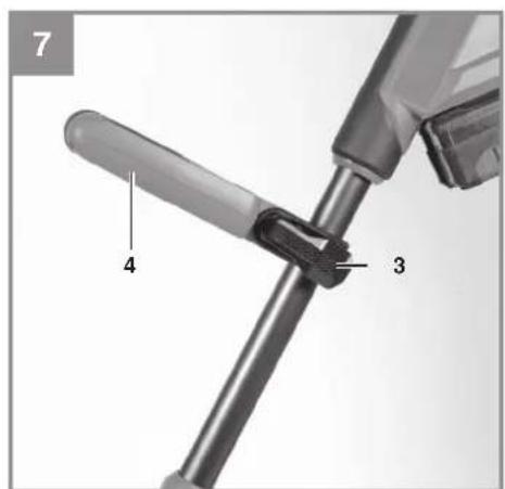
natural_image
Close-up of a mechanical pipe fitting with labeled component '6' and directional arrows indicating movement (no text or symbols beyond label)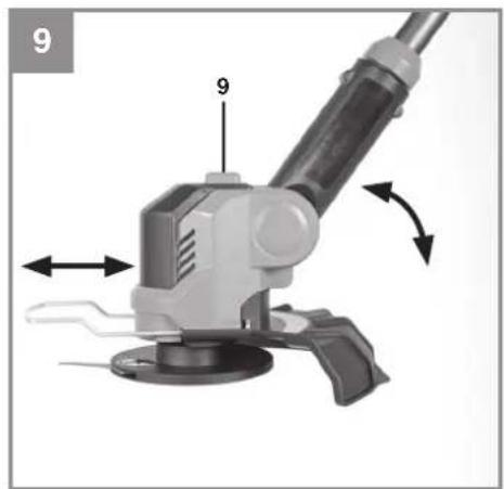
natural_image
Mechanical tool with labeled parts and directional arrows indicating motion (no text or symbols present)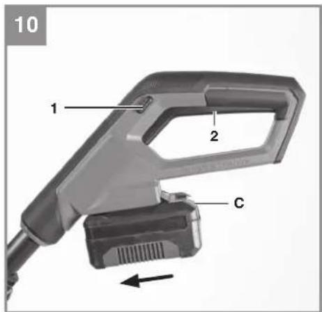
natural_image
Close-up of a black CHANCE brand phone with a power button and arrow indicator (no readable text or symbols beyond branding)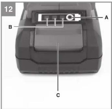
natural_image
Technical line drawing showing two mechanical assembly steps with no visible text or symbols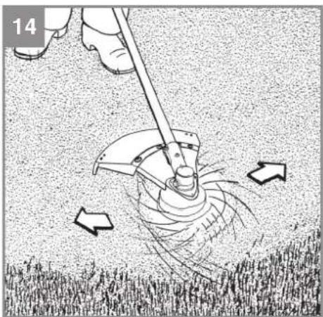
natural_image
Illustration of a person using a manual tool to lift a large mechanical component, with arrows indicating motion (no text or symbols)
natural_image
Close-up of a mechanical device with a black lever and attached components (no visible text or symbols)
natural_image
Close-up of a mechanical component with a circular housing and central hub (no visible text or symbols)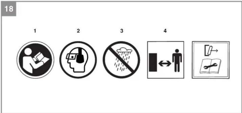
natural_image
Close-up of a hand using a screwdriver to adjust or install a mechanical component with a fan-like structure (no visible text or symbols)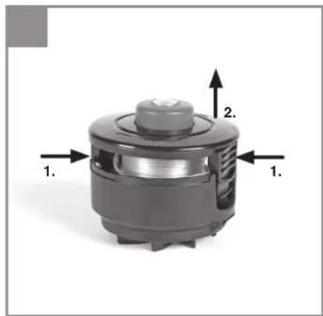
natural_image
3D rendering of a mechanical component with labeled parts (1. and 2.), no visible text or symbols beyond labels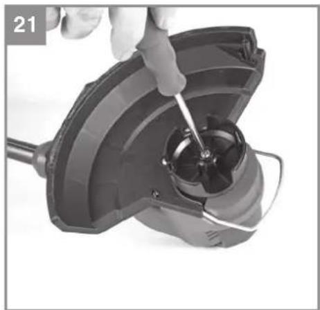
natural_image
Close-up of a hand using a screwdriver to adjust or install a mechanical component (no visible text or symbols)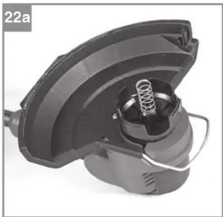
natural_image
Close-up of a mechanical component with a spring and housing (no visible text or symbols)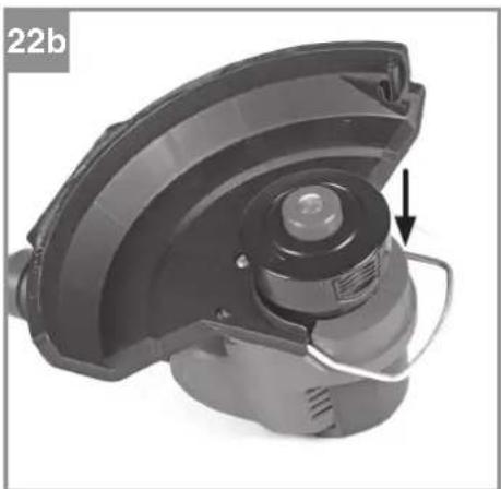
natural_image
Close-up of a mechanical device with a circular component and a labeled arrow pointing to it (no text or symbols on the device itself)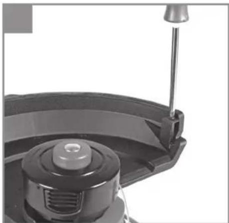
natural_image
Close-up of a mechanical component with a metallic lever and circular base (no visible text or symbols)D
Gefahr!
When using equipment, a few safety precautions must be observed to avoid injuries and damage. Please read the complete original operating instructions and safety information with due care. Keep these operating instructions in a safe place so that the information is available at all times. If you give the equipment to any other person, hand over these original operating instructions and the safety information as well. We cannot accept any liability for damage or accidents which arise due to failure to follow these instructions and the safety information.
Explanation of the warning signs on the tool (see Fig. 18)
- Read the instruction manual before starting!
- Wear goggles and ear muff s!
- Do not use the tool in the rain or under wet conditions. If water gets inside the tool this will increase the risk of an electric shock or malfunction and can lead to injuries.
- Keep other people out of the danger area!
- Warning! Remove the battery before working on the tool.
1. Safety information
The corresponding safety information can be found in the enclosed booklet.
WARNING!
Read all safety warnings, instructions, illustrations and specifications provided with this power tool. Failure to follow all instructions listed below may result in electric shock, fi re and/or serious injury.
Save all warnings and instructions for future reference.
This equipment is not allowed to be used by children. Children should be supervised so that they do not play with the equipment. Children are not allowed to carry out the cleaning or maintenance. This equipment is not allowed to be used by people with limited physical, sensory or mental capacities or by those with insufficient knowledge or experience unless they are supervised or instructed by a person who is responsible for them.
2. Layout and items supplied
2.1 Layout (Fig. 1/2)
1 Safety lock-off
2 On/Off switch
3 Clamping lever (additional handle)
4 Additional handle
4a Compartment for spare blades
5 Top part of the long handle
6 Height adjustment (union nut)
7 Bottom part of the long handle
8 Lock for rotatable motor head
9 Locking button for long handle tilt
10 Guard hood
11 Edge guide
12 Blade
13 Blade plate
14 Battery mount
15 Mounting screw
16 Blade plate fastening screw
17 Motor shaft
20 Thread head
21 String Blade
22 Screw
2.2 Items supplied
Please check that the article is complete as specified in the scope of delivery. If parts are missing, please contact our service center or the sales outlet where you made your purchase at the latest within 5 working days after purchasing the product and upon presentation of a valid bill of purchase. Also, refer to the warranty table in the service information at the end of the operating instructions.
- Open the packaging and take out the equipment with care.
- Remove the packaging material and any packaging and/or transportation braces (if available).
- Check to see if all items are supplied.
- Inspect the equipment and accessories for transport damage.
- If possible, please keep the packaging until the end of the guarantee period.
Danger!
The equipment and packaging material are not toys. Do not let children play with plastic bags, foils or small parts. There is a danger of swallowing or suff ocating!
- Grass trimmer
- Guard hood
- Blade plate
GB
Blade
Thread head
String Blade
Screw
• Original operating instructions
• Safety information
3. Intended use
The equipment is designed for cutting lawns and grassed areas. It is not designed to be used for public facilities, parks, sports centers, along roadways, or in agriculture and forestry.
The operating instructions as supplied by the manufacturer must be kept and referred to in order to ensure that the equipment is properly used and maintained.
Important. This equipment must not be used for composting purposes (shredding) as this could result in injury or damage to property.
The equipment may be used only for the tasks it is designed to handle. Any other use is deemed to be a case of misuse. The user/operator and not the manufacturer will be liable for any damage or injuries of any kind resulting from such misuse.
Please note that our equipment has not been designed for use in commercial, trade or industrial applications. Our warranty will be voided if the machine is used in commercial, trade or industrial businesses or for equivalent purposes.
Caution!
Residual risks
Even if you use this electric power tool in accordance with instructions, certain residual risks cannot be rules out. The following hazards may arise in connection with the equipment's construction and layout:
- Lung damage if no suitable protective dust mask is used.
- Damage to hearing if no suitable ear protection is used.
- Health damage caused by hand-arm vibrations if the equipment is used over a prolonged period or is not properly guided and maintained.
- Injuries and material damage caused by flying parts.
- Cut injuries if suitable protective clothing is not worn.
4. Technical data
Voltage....18Vd.c.
Speed n_0 8400 min ^-1
Cutting circle 0 25 cm
Protection IPX0
Protection class ....III
Weight: 2.0 kg
Caution!
The equipment is supplied without batteries and without a charger and is allowed to be used only with the lithium-ion batteries of the Power X-Change series!
The lithium-ion batteries of the Power X-Change series are allowed to be charged only with the Power-X charger.
Danger!
Sound and vibration
Sound and vibration values were measured in accordance with EN 62841.
Sound pressure level L_pA : 81.4 dB(A)
Uncertainty K_cA : 3 dB
Sound power level L_WA : 90.7 dB(A)
Uncertainty K_WA 3.16 dB
Guaranteed sound power level L_WA : ...... 94 dB(A)
Wear ear-muff s.
The impact of noise can cause damage to hearing.
Total vibration values (vector sum of three directions) determined in accordance with EN 62841.
Handle
Vibration emission value a_n ≤ 2.5 m/s^2
K uncertainty = 1.5 m/s²
Additional handle
Vibration emission value a_n ≤ 2.5 m/s^2
K uncertainty = 1.5 m/s²
The stated vibration emission levels and stated noise emission values were measured in accordance with a set of standardized criteria and can be used to compare one power tool with another.
GB
The stated vibration emission levels and stated noise emission values can also be used to make an initial assessment of exposure.
Warning:
The vibration and noise emission levels may vary from the level specified during actual use, depending on the way in which the power tool is used, especially the type of workpiece it is used for.
Limit the operating time!
All stages of the operating cycle must be considered (for example, times in which the electric tools are switched off and times in which the tool is switched on but operates without load).
Reduce noise generation and vibration to a minimum!
- Use only equipment that is in perfect condition.
- Maintain and clean the equipment regularly.
• Adapt your way of working to the equipment.
• Do not overload the equipment.
• Have the equipment checked if necessary. - Switch off the equipment when not in use.
- Wear gloves.
5. Before using the equipment
The equipment is supplied without batteries and without a charger!
5.1 Fitting the edge guide (Fig. 3)
Insert the edge guide (Item 11) into the guide openings (Item 10a) found on the guard hood.
5.2 Fitting the guard hood (Fig. 4)
Push the guard hood (Item 10) onto the mount on the motor housing as far as it will go and screw it securely in place with the mounting screw (Item 15).
5.3 Fitting the blade plate (Fig. 5)
Insert the blade plate (Item 13) onto the motor shaft (Fig. 2 / Item 17) and secure it with the fastening screw (Item 16).
5.4 Fitting the blade (Fig. 6-6a)
Place the blade in the groove on the blade mount (Item 13a) and pull outwards.
5.5 Adjusting the additional handle (Fig. 7)
Open the tightening screw (Item 3) and turn / push / tilt the additional handle (Item 4) to the required position. Close the tightening screw (Item 3) again. The additional handle is secured.
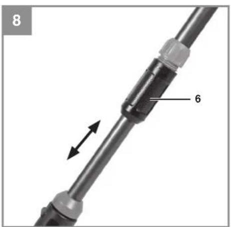
5.6 Height adjustment (Fig. 8)
Undo the union nut (Item 6) until the grass trim-mer handle can be moved in and out freely. Now set the required working height and secure the handle in this position by tightening the union nut again.
5.7 Adjusting the angle of tilt of the long handle (Fig. 9)
Press the button for adjusting the angle of tilt (Item 9). Now you can set the long handle to the required angle of tilt. To fix the angle of tilt, release the button and allow the handle to lock into position.
Warning!
Risk of injury!
If the angle of tilt of the long handle is wrongly set, you could injure yourself or the grass trimmer could become damaged.
- Use the grass trimmer only when the long handle and the button are latched in one of the three positions for the angle of tilt and when the long handle is securely seated.
- Do not use the grass trimmer if the long handle is not latched in place.
5.8 Installing the battery (Fig. 10)
Push the battery into the battery mount provided. The battery will be heard to click into place when it has been pushed fully in. To take out the battery, press the pushlock button (Item C) and remove the battery.
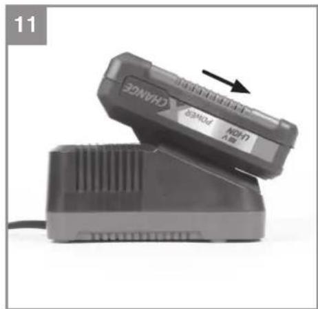
5.9 Charging the battery (Fig. 11)
- Take the battery pack out of the equipment. Do this by pressing the side pushlock buttons.
- Check that your mains voltage is the same as that marked on the rating plate of the battery charger. Insert the power plug of the charger into the mains socket outlet. The green LED will then begin to flash.
- Insert the battery pack into the battery charger.
- In section „Charger indicator“ you will find a table with an explanation of the LED indicator on the charger.
GB
The battery pack can become a little warm during the charging. This is normal.
If the battery pack fails to charge, check:
• whether there is voltage at the socket outlet
- whether there is good contact at the charging contacts
If the battery pack still fails to charge, send
• the charging unit
• and the battery pack
to our customer service center.
To ensure that items are properly packaged and delivered when you send them to us, please contact our customer service or the point of sale at which the equipment was purchased.
When shipping or disposing of batteries and cordless tools, always ensure that they are packed individually in plastic bags to prevent short circuits and fi res.
To ensure that the battery pack provides long service, you should take care to recharge it promptly. You must recharge the battery pack when you notice that the performance of the device drops. Never allow the battery pack to become fully discharged. This will cause it to develop a defect.
5.10 Battery capacity indicator (Fig. 12)
Press the switch for the battery capacity indicator (Item B). The battery capacity indicator (Item A) shows the charge status of the battery using 3 LEDs.
All 3 LEDs are lit:
The battery is fully charged.
2 or 1 LED(s) are lit:
The battery has an adequate remaining charge.
1 LED fl ashes:
The battery is empty, recharge the battery.
All LEDs blink:
The battery temperature is too low. Remove the battery from the equipment, keep it at room temperature for one day. If the fault reoccurs, this means that the rechargeable battery has undergone exhaustive discharge and is defective. Remove the battery from the equipment. Never use or charge a defective battery.
6. Operation
Please note that the statutory regulations governing noise abatement may differ from one location to another.
Danger! The guard hood must be fitted when carrying out work.
Each time before use, check the following :
- That the equipment is in perfect condition and that the safety devices and cutting devices are complete.
• That all screws are securely fastened.
• That all moving parts move smoothly.
6.1 Switching the equipment on and off
6.1.1 Switching on (Fig. 10)
Press the left or the right safety lock-off (Item 1) and the On/Off switch (Item 2). Once the tool is running, you can release the safety lock-off.
6.1.2 Switching off
Release the On/Off switch.
6.2 Practical tips
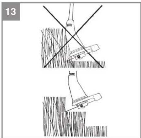
Practice all the work steps with the motor switched off and without the rechargeable battery before you start to use the equipment. Only ever cut grass that is dry. If the grass is long, the grass must be cut shorter in stages (Fig. 13).
Using a brush or similar, carefully remove all residual grass from the underside of the guard hood at regular intervals.
Different cutting methods
Caution! To use the edge guide along walls or objects, pull the edge guide out toward the front (Fig. 9). Push it back in when not in use (Fig. 9).
Please note: Even if done carefully, cutting around foundations, stone or concrete walls, etc. will result in above-normal wear on the cutting elements.
Trimming/mowing
Swing the trimmer from side to side in a scything motion. Always keep the cutting element parallel to the ground. Check the site and decide which cutting height you require. Guide and hold the cutting element at the required height to ensure that you cut evenly.
GB
Low trimming
Hold the trimmer right in front of you at a slight angle so that the cutting element is above the ground and strikes the correct target. Always cut away from yourself. Never draw the string trimmer towards yourself.
Cutting along fences / foundations Edge guide recommended!
Approach wire mesh fences, plank fences, natural stone walls and foundations slowly so that you can cut close to them without striking the obstacle with the cutting element.
Trimming around trees
Edge guide recommended!
When trimming around tree trunks, approach slowly so that the cutting element does not strike the bark. Walk around the tree, cutting from left to right. Approach grass or weeds with the tip of the cutting element and tilt the tool forwards slightly. Warning: Take extreme care during mowing work. When doing such work keep a distance of 30 meters between yourself and other people or animals.
Mowing
When mowing down to the ground you will cut all the vegetation. To do this, tilt the tool at an angle of 30^ to the right. Place the handle in the required position. Remember the increased risk of injury to the user, onlookers and animals, and the danger of damaging property due to thrown objects (for example stones) (Fig. 14).
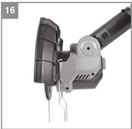
Using the grass trimmer as an edge trimmer (Fig. 15-16)
To cut the edges of lawns alongside e.g. flower beds (vertical cutting), the grass trimmer can be converted into a lawn edge trimmer.
The lock (Item 8) latches in the angle of tilt adjustment (Item 8a). While holding the angle of tilt adjustment (Item 8a) in place, pull the long handle upwards out of the lock and turn it 180^ counterclockwise until it latches home. Tilt the long handle as required. Use the edge guide.
Return the motor head in reverse order to its original position in order to use it as a grass trimmer.
7. Cleaning, maintenance and ordering of spare parts
Danger!
Remove the rechargeable battery/batteries.
7.1 Cleaning
- Keep all safety devices, air vents and the motor housing free of dirt and dust as far as possible. Wipe the equipment with a clean cloth or blow it down with compressed air at low pressure.
• We recommend that you clean the equipment immediately after you use it. - Clean the equipment regularly with a damp cloth and some soft soap. Do not use cleaning agents or solvents; these may be aggressive to the plastic parts in the equipment. Ensure that no water can get into the interior of the equipment. The ingress of water into an electric tool increases the risk of an electric shock.
- Use a brush to remove deposits from the safety guard.
7.2 Replacing the blade (Fig. 17)
Danger! Only the original accessories may be used. Metal cutting elements are dangerous and not permitted.
Push the blade inwards, press it against the blade through the opening in the blade plate and remove the blade. The blade is inserted in the reverse order (see also section 5.4).
7.3 Maintenance
There are no other parts inside the equipment which require maintenance.
7.4 Ordering spare parts
Please provide the following information on all orders for spare parts:
• Model/type of the equipment
• Article number of the equipment
• ID number of the equipment
- Spare part number of the required spare part For our latest prices and information please go to www.Einhell-Service.com
Spare blade set Art. No.: 34.057.38
Spare blade box Art. No.: 34.057.39
GB
8. Disposal and recycling
The equipment is supplied in packaging to prevent it from being damaged in transit. The raw materials in this packaging can be reused or recycled. The equipment and its accessories are made of various types of material, such as metal and plastic. Defective components must be disposed of as special waste. Ask your dealer or your local council.
9. Storage
Remove the rechargeable battery/batteries. Store the equipment and accessories in a dark and dry place at above freezing temperature. The ideal storage temperature is between 5 and 30 °C. Store the electric tool in its original packaging.
10. Transport
- Always carry the tool with one hand on the handle and the other on the additional handle. Do not carry the tool by the motor housing.
- Secure the tool against slipping if transporting it by car.
- If possible, use the original packaging for transportation.
11. Faults
The equipment does not work:
Check that the battery is charged and whether the charging unit is working. If the equipment will not work in spite of the voltage supply being OK, please send it to the customer service address below.
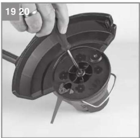
12. Thread head
12.1 Assembly (Fig. 19-23)
- Unscrew the blade plate
- Press on both ribbed surfaces of the spool housing cover and remove it along with the spool. Remove the pressure spring.
- Place the underside of the spool housing on the motor shaft and fasten it tightly with the supplied fastening screw.
- Put the pressure spring on. Fit the spool housing cover and spool onto the underside of the spool housing.
- Fasten the string blade onto the guard hood with the screw included with the cutting head. Warning! Take care not to injure yourself on the string blade. Wear protective gloves.
12.2 Operation
Danger! Do not use any kind of metal wire or metal wire encased in plastic in the line spool. This may cause serious injuries to the user.
The grass trimmer has a semi-automatic line extension system (automatic jog line feed). Each time you activate the semi-automatic line extension system, the line is automatically extended to ensure that you can cut your lawn with the perfect cutting width at all times. To extend the cutting line, run the motor and tap the line spool on the ground. This will automatically extend the line. The blade on the guard hood will cut the line to the permissible length. Please note that the more often you activate the semi-automatic line extension system, the more the line will wear.
Note: If the line is too long when you use the equipment for the fi rst time, the surplus end of it will be cut by the blade on the guard hood. If the line is too short when you start the equipment for the fi rst time, press the knob on the line spool and pull the line hard. When you then start the machine for the fi rst time the line will be cut to the perfect length automatically.
GB
13. Charger indicator
| Indicator status Explanations and actions | ||
| Red LED Green LED | ||
| Off | Flashing | Ready for useThe charger is connected to the mains and is ready for use; there is no battery pack in the charger |
| On Off Charging | The charger is charging the battery pack in quick charge mode. The charging times are shown directly on the charger.Important! The actual charging times may vary slightly from the stated charging times depending on the existing battery charge. | |
| Off | On | The battery is charged and ready for use. (READY TO GO)The unit then changes over to gentle charging mode until the battery is fully charged.To do this, leave the rechargeable battery on the charger for approx. 15 minutes longer.Action:Take the battery pack out of the charger. Disconnect the charger from the mains supply. |
| Flashing Off | Adapted charging | The charger is in gentle charging mode.For safety reasons the charging is performed less quickly and takes more time. The reasons can be:- The rechargeable battery has not been used for a very long time.- The battery temperature is outside the ideal range.Action:Wait for the charging to be completed; you can still continue to charge the battery pack. |
| Flashing Flashing Fault | Charging is no longer possible. The battery pack is defective.Action:Never charge a defective battery pack.Take the battery pack out of the charger. | |
| On On Temperature fault | The battery pack is too hot (e.g. due to direct sunshine) or too cold (below 0^ ).Action:Remove the battery pack and keep it at room temperature (approx. 20^ ) for one day . | |
GB
Disposal

Power tools, rechargeable batteries, accessories and packaging should be sorted for environmental-friendly recycling.
Do not dispose of power tools and batteries/rechargeable batteries into household waste!
Only for EU countries:
According to the Directive 2012/19/EU on waste electrical and electronic equipment and its transposition into national law, power tools that are no longer usable, and, according to the Directive 2006/66/EC, defective or drained batteries must be collected separately and disposed of in an environmentally correct manner.
If disposed incorrectly, waste electrical and electronic equipment may have harmful effects on the environment and human health, due to the potential presence of hazardous substances.
Only for United Kingdom:
According to The Waste Electrical and Electronic Equipment Regulations 2013 (SI 2013/3113) (as amended) and the Waste Batteries and Accumulators Regulations 2009 (SI 2009/890) (as amended), products that are no longer usable must be collected separately and disposed of in an environmentally friendly manner.
The reprinting or reproduction by any other means, in whole or in part, of documentation and papers accompanying products is permitted only with the express consent of the Einhell Germany AG.
Subject to technical changes
GB
Service information
We have competent service partners in all countries named on the guarantee certificate whose contact details can also be found on the guarantee certificate. These partners will help you with all service requests such as repairs, spare and wearing part orders or the purchase of consumables.
Please note that the following parts of this product are subject to normal or natural wear and that the following parts are therefore also required for use as consumables.
| Category Example | |
| Wear parts* Blade head, Blade plate, Line spool holder,Battery | |
| Consumables* Blade, Line, Line spool | |
| Missing parts |
* Not necessarily included in the scope of delivery!
In the effect of defects or faults, please register the problem on the internet at www.Einhell-Service.com. Please ensure that you provide a precise description of the problem and answer the following questions in all cases:
• Did the equipment work at all or was it defective from the beginning?
• Did you notice anything (symptom or defect) prior to the failure?
• What malfunction does the equipment have in your opinion (main symptom)?
Describe this malfunction.
F
Danger!
Retirez le/les accumulateur(s).
7.1 Nettoyage
Retirez le/les accumulateur(s).
Negotovost K_pA : 3 dB
Svetle sve 3 LE-diode:
X 2006/42/EC
□ Annex IV
Notified Body:
Reg. No.:
X 2000/14/EC_2005/88/EC
□ Annex V
X Annex VI
Noise: measured L_WA = 91.5 dB (A); guaranteed L_WA = 94 dB (A)
P = kW; L/∅ = 25 cm
Notified Body: TÜV SÜD Industrie Service GmbH (NB 0036)
2012/46/EU_(EU)2016/1628 Emission No.:
Standard references: EN 62841-1; IEC 62841-4-4; EN IEC 55014-1; EN IEC 55014-2
Subject to change without notice
Archive-File/Record: NAPR033629
Documents registrar: Josef Landauer
Wiesenweg 22, D-94405 Landau/Isar
* 1. SB Cordless lawm trimer - F Coupou-bordou a accumulator - Trimmer a batteria - OKW Bettsredovan grastinimra - S Bateralban gristinimra - A Kalukumulatoru swnunu senioka-à - SK Akumulatoru strunev kosačka - NL Accegazontrimmer - E Rectorodos de cezdopd za bateria - FIN Akuledyttimran raohtrinimra - SLO Bateraljsa kositima za travo - N Aklu - párzattrimmer - RO Trimmer peniu gazon za accumulator - GNI Myogen mýročnosup jertno mýrogrup - P rodsodor de reva sam lo - HR/KN Akumulatoru trimer za travnak - RS Akumulatoru trimer za travnak - PL Akumulatoru trimer za travnak - LV Akumulatoru dálapa trimer - LT Akumulatoru vajarjove - BG Akumulatoru kositima za podlăvanehne na třepe - UKI AKUMLAURIPINA VAMONOSKORA - MK Triper za třepe na baterja

Declaration of conformity
We, Einhell UK Ltd
Champions Business Park, First Floor Unit 10, Arrowe Brook Rd, Upton, Wirral CH49 0AB, United Kingdom
declare the conformity to UK standards and legislation was assessed for:
Cordless Lawn Trimmer GE-CT 18/25-1 Li (Einhell)
UK legislation
□ Simple Pressure Vessels (Safety) Regulation
□ Electrical Equipment (Safety) Regulation
□ Radio Equipment Regulation
□ Personal Protective Equipment Regulation
☐ The Ecodesign for Energy-Related Products and Energy Information Regulation
X The Restriction of the Use of Certain Hazardous Substances in Electrical and Electronic Equipment Regulation
X Noise Emission in the Environment by Equipment for use Outdoors Regulation
X Electromagnetic Compatibility Regulation
□ Measuring Instruments Regulation
☐ Pressure Equipment (Safety) Regulation
Annex V
X Annex VI
Noise:measuredL w0 =91.5 dB (A); guaranteed L w0 =94 dB (A)
P = kW; L/∅ = 25 cm
Approved Body: TÜV SÜD Industrie Service GmbH (NB 0036)
X Supply of Machinery (Safety) Regulation
□ Annex IV
UK Approved Body:
UKTE Certifi cate No.:
Standards: EN 62841-1; IEC 62841-4-4; EN IEC 55014-1; EN IEC 55014-2
Wirral, 2024.10.02

Archive-File/Record: NAPR033629
Article Number: 34.112.56 I.-No.: 21014
Subject to change without notice Wiesenweg 22, 94405 Landau/Isar, Germany
Documents registrar: Josef Landauer
EH 10/2024 (01)

- D
- Gefahr!
- Explanation of the warning signs on the tool (see Fig. 18)
- Safety information
- WARNING!
- Layout and items supplied
- Layout (Fig. 1/2)
- Items supplied
- Danger!
- GB
- Intended use
- Caution!
- Residual risks
- Technical data
- Sound and vibration
- Wear ear-muff s.
- Handle
- Additional handle
- Warning:
- Limit the operating time!
- Reduce noise generation and vibration to a minimum!
- Before using the equipment
- The equipment is supplied without batteries and without a charger!
- Fitting the edge guide (Fig. 3)
- Fitting the guard hood (Fig. 4)
- Fitting the blade plate (Fig. 5)
- Fitting the blade (Fig. 6-6a)
- Adjusting the additional handle (Fig. 7)
- Height adjustment (Fig. 8)
- Adjusting the angle of tilt of the long handle (Fig. 9)
- Risk of injury!
- Installing the battery (Fig. 10)
- Charging the battery (Fig. 11)
- To ensure that items are properly packaged and delivered when you send them to us, please contact our customer service or the point of sale at which the equipment was purchased.
- Battery capacity indicator (Fig. 12)
- All 3 LEDs are lit:
- or 1 LED(s) are lit:
- LED fl ashes:
- All LEDs blink:
- Operation
- Each time before use, check the following :
- Switching the equipment on and off
- Switching on (Fig. 10)
- Switching off
- Practical tips
- Different cutting methods
- Trimming/mowing
- Low trimming
- Cutting along fences / foundations Edge guide recommended!
- Trimming around trees
- Edge guide recommended!
- Mowing
- Using the grass trimmer as an edge trimmer (Fig. 15-16)
- Cleaning, maintenance and ordering of spare parts
- Cleaning
- Replacing the blade (Fig. 17)
- Maintenance
- Ordering spare parts
- Disposal and recycling
- Storage
- Transport
- Faults
- The equipment does not work:
- Thread head
- Assembly (Fig. 19-23)
- Operation
- Charger indicator
- Disposal
- Only for EU countries:
- Only for United Kingdom:
- Service information
- F
- Nettoyage
- Svetle sve 3 LE-diode:
- Standard references: EN 62841-1; IEC 62841-4-4; EN IEC 55014-1; EN IEC 55014-2
- Declaration of conformity
- Cordless Lawn Trimmer GE-CT 18/25-1 Li (Einhell)
- UK legislation
Brand : EINHELL
Model : GE-CT 18/25-1 Li
Category : Grass trimmer