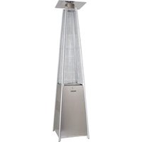
PHÖNIX - Heating Sonnenkönig - Free user manual and instructions
Find the device manual for free PHÖNIX Sonnenkönig in PDF.


User questions about PHÖNIX Sonnenkönig
0 question about this device. Answer the ones you know or ask your own.
Ask a new question about this device
Download the instructions for your Heating in PDF format for free! Find your manual PHÖNIX - Sonnenkönig and take your electronic device back in hand. On this page are published all the documents necessary for the use of your device. PHÖNIX by Sonnenkönig.
USER MANUAL PHÖNIX Sonnenkönig
natural_image
Exterior view of a modern outdoor café fire extinguisher (no signage or text visible)
FIRMA
Sonnenkönig of Switzerland
Olensbachstrasse 9-15
CH-9631 Ulisbach
Tel. Int. +41 58 611 60 00
Tel. Nat. 0848 870 850
Artikelnr. 30310188
Version 22.04.2021
text_image
Exploded view diagram of a solar panel assembly with labeled components from A to Jtext_image
K M 19 19 0natural_image
Line drawing of a surveying instrument with tripod base and top platform (no text or symbols)natural_image
Technical line drawing of a tall industrial chimney with structural components and mounting base (no text or symbols)10
text_image
17 20 10 L I 0natural_image
Technical line drawing of a mechanical component with no visible text or symbolsnatural_image
Technical line drawing of a mechanical assembly with curved components and a central housing (no text or symbols)natural_image
Technical line drawing of a gas cylinder mounted on a ladder, showing internal components and mounting brackets (no text or symbols)natural_image
Exterior view of a modern outdoor fire extinguisher (no signage or text visible)
MAISON
Sonnenkönig of Switzerland
Olensbachstrasse 9-15
CH-9631 Ulisbach
Tel. Int. +41 58 611 60 00
Tel. Nat. 0848 870 850
N° Article 30310188
Version 22.04.2021
01 - TABLE DES MATIÈRES
01 - TABLE DES MATIÈRES 20
02 - AVERTISSEMENTS 21
03 - CONTENU 23
04 - ASSEMBLÉE 24
05 - CONTRÔLE D'ÉTANCHÉITÉ 31
06 - UTILISATION 31
07 - MISE EN SERVICE 32
08 - NETTOYAGE, ENTRETIEN ET MAINTENANCE 33
09 - DONNÉES TECHNIQUES 33
10 - CONFORMITÉ / RÉSOLUTION DE PROBLÈMES 34
text_image
Exploded view diagram of a solar panel assembly with labeled components from A to JN° Description Qté
text_image
K M 19 19 0N° Description Qté
natural_image
Line drawing of a surveying instrument with tripod base and top panel (no text or symbols)natural_image
Technical line drawing of a tall industrial chimney with structural components and mounting base (no text or symbols)10
N° Description Qté
text_image
17 20 10 I L 0N° Description Qté
natural_image
Technical line drawing of a mechanical component with no visible text or symbolsnatural_image
Technical line drawing of a mechanical assembly with curved components and a central hub (no text or symbols)natural_image
Technical line drawing of a cylindrical gas cylinder mounted on a ladder, with no visible text or symbols.Table of the injector
10 - CONFORMITÉ / RÉSOLUTION DE PROBLÈMES
Garantie
Modifications techniques
natural_image
Exterior view of a modern outdoor fire extinguisher (no signage or text visible)
DITTA
Sonnenkönig of Switzerland
Olensbachstrasse 9-15
CH-9631 Ulisbach
Tel. Int. +41 58 611 60 00
Tel. Nat. 0848 870 850
Nº articolo 30310188
Versione 22.04.2020
01 - INDICE
01 - INDICE 38
02 - AVVISI 39
03 - CONTENUTO 41
04 - MONTAGGIO 42
05 - CONTROLLO DELL'IMPERMEABILITÀ 49
06 - UTILIZZO 49
07 - STARTUP MESSA IN SERVIZIO 50
08 - PULIZIA, CURA E MANUTENZIONE 51
09 - DATI TECNICI 51
10 - CONFORMITÀ / RISOLUZIONE DEI PROBLEMI 52
text_image
Exploded view diagram of a solar panel assembly with labeled components from A to JN° Descrizione Qtà
text_image
K M 19 19 0N° Descrizione Qtà
natural_image
Line drawing of a surveying instrument with tripod base and top platform (no text or symbols)natural_image
Technical line drawing of a tall industrial chimney with structural components and mounting base (no text or symbols)10
N° Descrizione Qtà
text_image
17 20 10 I L 0N° Descrizione Qtà
natural_image
Technical line drawing of a mechanical component with no visible text or symbolsnatural_image
Technical line drawing of a mechanical assembly with curved components and a central housing (no text or symbols)natural_image
Technical line drawing of a cylindrical gas cylinder mounted on a metal frame structure (no text or symbols)Suggerimento:
natural_image
Exterior view of a modern outdoor fire extinguisher (no signage or text visible)
COMPANY
Sonnenkönig of Switzerland
Olensbachstrasse 9-15
CH-9631 Ulisbach
Tel. Int. +41 58 611 60 00
Tel. Nat. 0848 870 850
Item No. 30310188
Version 22.04.2020
01 - CONTENT
01 - CONTENT 56
02 - WARNING NOTICE 57
03 - SCOPE OF DELIVERY 59
04 - ASSEMBLY 60
05 - GASLEAK TESTING 67
06 - CONTROL 67
07 - STARTUP 68
08 - CLEANING, CARE AND MAINTENANCE 69
09 - TECHNICAL DETAILS 69
10 - CONFORMITY / TROUBLE SHOOTING 70
Please read and understand this instruction manual completely before attempting to assemble, install and use the product!
This Manual contains critical information about the assembly, usage and maintenance of this device. General safety information is presented on these first pages and can also be found throughout the manual. Keep this manual for future reference and to educate new users of this product. This manual should be read in conjunction with the labeling on the product. Safety precautions are essential when using mechanical or propane powered equipment. These precautions are required when using, storing and maintaining this product. If this equipment is used with due respect and caution, the possibility of personal injury or damage to property will be reduced.
EXPLOSION - FIRE HAZARD
- Store fuels such as building materials, paper or cardboard, at a safe distance from the heater, as recommended in the instructions.
- Ensure sufficient clearance around the air openings in the combustion chamber.
- Never use the heater in rooms that contain or may contain volatile or airborne fuels or products such as gasoline, solvents, paint thinner, dust particles or unknown chemicals.
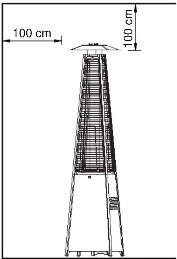
- During operation, this product may be a source of ignition. Keep the area around the heater free of combustible materials such as gasoline, thinner, cleaning solutions, and other flammable gases and liquids. Do not use the heater in areas with high dust generation. Minimum distance of the heater from flammable materials: 100 cm to the side and 100 cm from the top.
CARBON MONOXIDE - DANGER
- This heater is a combustion device. All combustion devices produce carbon monoxide (CO) during the combustion process. This product produces small, non-hazardous quantities of CO when used and maintained in accordance with all warnings and instructions. Care must be taken not to block the airflow to or from the heater.
- Carbon monoxide poisoning causes flu-like symptoms, watery eyes, headaches, dizziness, fatigue, and possibly death. You cannot see or smell carbon monoxide. If these symptoms occur during operation of this device, get fresh air immediately!
- For outdoor use only.
- Never use indoors or in other unventilated or enclosed spaces.
• This heater consumes air (oxygen).
DANGEROUS FUELS
- Never store propane near strong heat sources, naked flames, pilot lights, direct sunlight, other sources of ignition or at temperatures above 49°C.
- Propane gases are heavier than air and may accumulate in low locations. If you smell gas, leave the area immediately.
-
Never install or remove propane cylinders while the heater is operating, near flames, pilot lights, other sources of ignition, or when the heater is hot.
-
This heater is highly incandescent during use and may ignite flammable materials near the burner. Keep flammable materials at least 100 cm from the sides and 100 cm from the top. Keep gasoline and other flammable liquids and gases away from the heater.
- Store propane cylinders outdoors or in a well-ventilated area out of the reach of children. Never store propane cylinders indoors (house, garage, etc.). If the heater is to be stored indoors, disconnect the propane cylinder for outdoor storage.
- Do not store or use gasoline or other flammable gases and liquids near this or any other appliance. Do not store an unplugged gas cylinder near this or any other appliance.
- This product is powered by propane gas. Propane gas is invisible, odorless and flammable. Normally, a so-called odorant is added to help detect leaks more easily, and it can be described as a "rotten egg" smell.
- The odorant volatilizes over time, so leaking gas cannot always be detected by smell alone.
• Propane gas is heavier than air, and escaping propane gas sinks to the ground. - It can be ignited by ignition sources such as matches, lighters, sparks, or open flames of any kind, even if they are many feet away from the original leak.
- Use only propane gas that is set up for vapor extraction.
RISK OF BURNS
- Never leave the heater unattended when it is hot or in operation.
- Keep out of the reach of children.
- Certain materials or objects, when stored under the heater, are exposed to radiant heat and could be seriously damaged.
SERVICE SECURITY
- Keep all connections and fittings clean. Make sure that the valve outlet of the propane cylinder is clean.
- During assembly, check all connections and fittings for leaks using soapy water. Never use a flame.
- Use only as a heater. Never modify in any way or use with any appliance.
- Warn children and adults of the dangers of high surface temperatures. Keep sufficient distance from these surfaces to avoid possible skin burns or the ignition of clothing.
• Always supervise small children when they are near the heater. - Keep all flammable materials away from the unit and do not place anything on top of or in the immediate area around the unit.
- Install any protective devices that have been removed for servicing the appliance before putting it back into operation.
- Installation and repair should only be performed by qualified service personnel. Have the heater professionally inspected before use and once a year.
- More frequent cleaning may be required if necessary.
- It is essential to ensure that the control housing, burner and circulating air duct of the appliance remain clean.
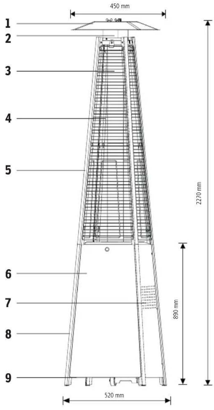
text_image
450 mm 2270 mm 890 mm 520 mm 1 2 3 4 5 6 7 8 910

11

12
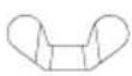
13

17

18

19
No Description Qty
1 Reflector panel 3
2 Flameguard 1
3 Glass tube 1
4 Protective device 1
5 Upper support 1
6 Front cover 1
7 Side cover 1
8 Lower support 1
9 Bottom plate 3
10 Chain 1
11 Screw cap 3
12 Flange nut M8 4
13 Wing nut 3
14 Mounting bracket 4
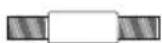
15 Small bolt 3
16 Bolt 3
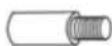
17 Screw M4 * 10 mm 1
18 Screw M8 * 12 mm 4
19 Screw 3/16" 68
20 Knob 1
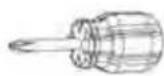
21 Screwdriver 1
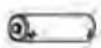
22 Battery AAA 1
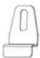
14
15
16

20
21
22
RESOURCES

text_image
Exploded view diagram of a solar panel assembly with labeled components from A to JNo Description Qty
A Reflector Panel 1
B Flame guard 1
C Cover plate 1
D Glass tube 1
E Upper support 4
F Protective cover on top 4
G Black silicone ring 1
H Side cover bottom 3
No Description Qty
I Front cover bottom 1
J Gas hose + regulator 1
K Base unit with burner 1
L Control box 1
M Lower support 4
N Wheels 1
O Base plate 1
No Description Qty
N Wheels 1
0 Base plate 1
12 Flange nut M8 4
18 Screw M8 * 12 mm 4
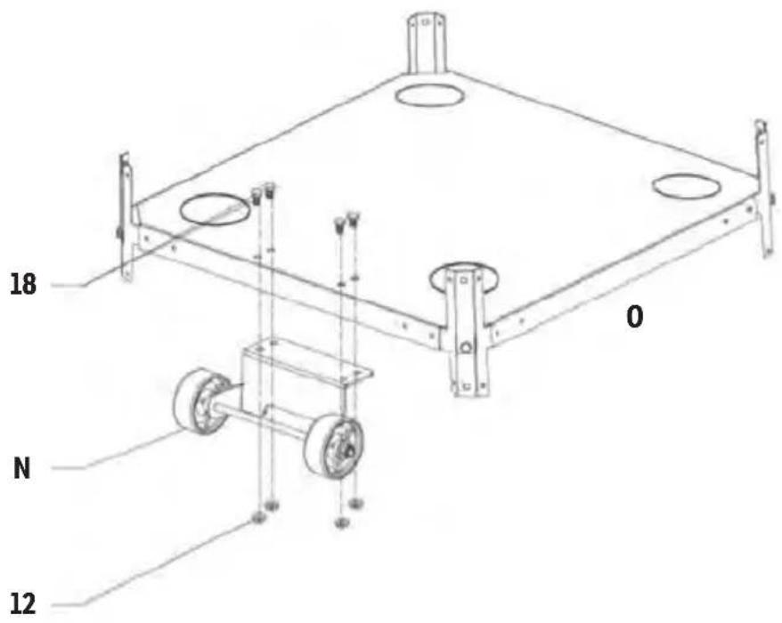
Step 1
Mount the wheels (N) to the base plate (O). Fasten the wheel assembly (N) to the base plate (O) with 4 pieces M8x12 mm screw (18) and 4 pieces M8 flange nut (12).
text_image
18 0 N 1202
No Description Qty
K Base unit with burner 1
M Lower support 4
0 Base plate 1
19 Screw 3/16" 12
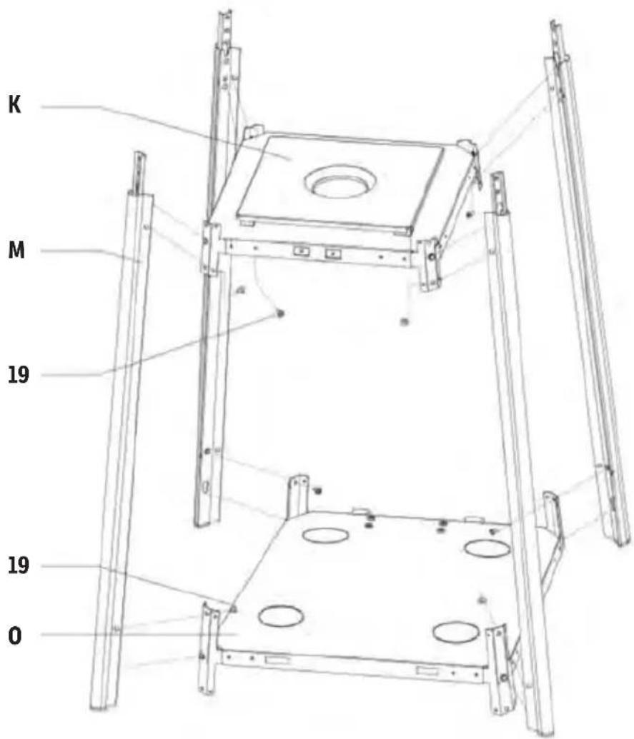
Step 2
Insert the pins of the bottom plate (O) into the holes of the lower support (M) and press to secure the pins. Use 12 pieces of 3/16" (19) screw to secure the lower support (M) and the bottom plate (O). Use 8 pieces of screw 3/16" (19) to secure the lower support (M) and the base unit with burner (K).
text_image
K M 19 19 0No Description Qty
K Base unit with burner 1
L Control box 1
19 Screw 3/16" 4
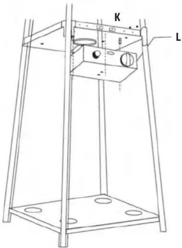
Step 3
Mount the control box (L). Fasten the control box (L) to the base unit with burner (K) using 4 pieces of 3/16" (19) screw.
text_image
K L04
No Description Qty
E Upper support 4
K Base unit with burner 1
19 Screw 3/16" 16
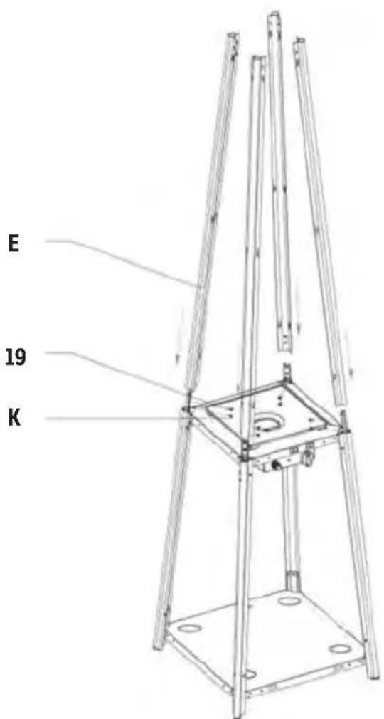
Step 4
Mount the upper support (E). Insert the 4 pieces of the upper support (E) on the base unit with burner (K). Secure them with 16 pieces of 3/16" screw (19).
text_image
E 19 KNo Description Qty
C Cover plate 1
E Upper support 4
19 Screw 3/16" 8
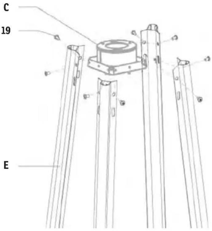
Step 5
Mount the top plate (C) to the upper support (E). Fasten the top plate (C) to the upper support (E) with 8 pieces of 3/16" (19) screw.
text_image
C 19 E06
No Description Qty
A Reflector Panel 1
B Flame guard 1
C Cover plate 1
11 Screw cap 3
13 Wing nut 3
15 Small bolt 3
16 Bolt 3
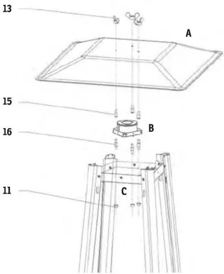
Step 6
Mount the flame guard (B) on the cover plate (C), the reflector panel (A) on the flame guard (B). Screw the 3 piece bolt (16) onto the cover plate (C), place the 3 piece screw cap (11) onto the bottom of the bolt (16), secure it with 3 piece bolt (16) and 3 piece screw cap (11). Screw the 3 pieces small bolt (15) on the bolt (16), then put the reflector panel (A) on the small bolt (15) and secure it with 3 pieces small bolt (15) and 3 pieces wing nut (13).
text_image
13 A 15 B 16 C 11No Description Qty
C Cover plate 1
D Glass tube 1
G Black silicone ring 1
K Base unit with burner 1
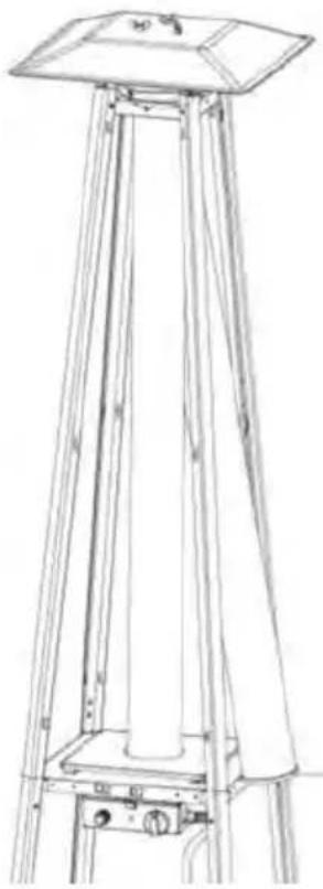
Step 7
Carefully assemble the glass tube (D) by lifting it and inserting it through the center hole in the top plate (C). Ensure that the black silicone ring (G) is attached to the lower edge of the glass tube (D) through the hole in the lower plate cover and onto the base unit with burner (K). Check and ensure that the glass tube (D) is correctly positioned and completely covers the center hole of the base unit with burner (K).
WARNING! The black silicone ring (G) must be in place before operating the heater.
natural_image
Line drawing of a surveying instrument with tripod base and top platform (no text or symbols)To facilitate installation, place the black silicone ring on the center plate and then install the glass tube. Make sure that the edge of the glass tube is firmly seated in the black silicone ring.
08
No Description Qty
F Top protective cover 4
14 Mounting bracket 1
19 Screw 3/16" 4
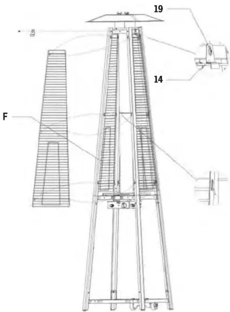
Step 8
Mount the protective cover on top (F). Hang the hooks of the protective cover on top (F) into the holes of the brackets. Secure the top protective cover (F) with mounting brackets (14) and 4 pieces of 3/16" screws (19).
text_image
19 14 FNo Description Qty
H Side panel bottom 3
19 Screw 3/16" 4
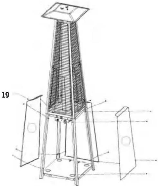
Step 9
Attach the three side panels to the bottom (H) of the heater with 12 3/16" (19) screws.
Note: Do not cover the front where the control knob is located.
natural_image
Technical line drawing of a tall industrial chimney with structural components and mounting base (no text or symbols)10
No Description Qty
1 Front panel bottom 1
L Control box 1
0 Bottom plate 1
10 Chain 1
17 Screw M4 * 10 mm 1
20 Knob 1
21 Screwdriver 1
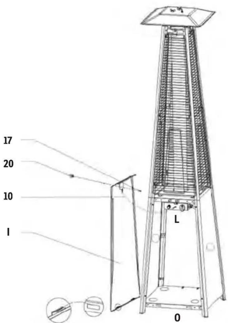
Step 10
Mount the knob (20) on the M4x10 screw (17) with the screwdriver (21). Hang the chain (10) in the hole on the control box (L) and insert the hook of the front panel bottom (I) in the holes of the bottom plate (O).
GASLEAK TESTING
Please make sure that you follow the instructions on page 67 before operating the heater.
text_image
17 20 10 I L 0No Description Qty
L Control box 1
22 Battery AAA 1
Step 11
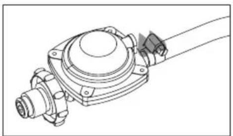
Hose connection for propane.
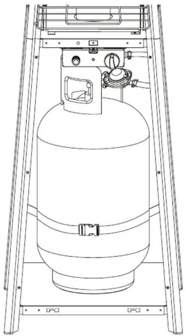
WARNING: Be careful that the hose does not come in contact with the high temperature surfaces, this could cause melting or leakage, which could cause a fire. After the cylinder is in place inside the furnace, secure it.
Battery for ignition
Turn the entire ignition knob to the left. Below you will find the device where the battery must be inserted for ignition.
natural_image
Technical line drawing of a mechanical component with no visible text or symbolsHose and regulator connection
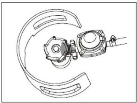
natural_image
Technical line drawing of a mechanical assembly with no visible text or symbolsRegulator and cylinder connection
natural_image
Technical line drawing of a cylindrical gas cylinder mounted on a ladder, with no visible text or symbols.Tip: We recommend replacing gas hoses every eight to ten years.
text_image
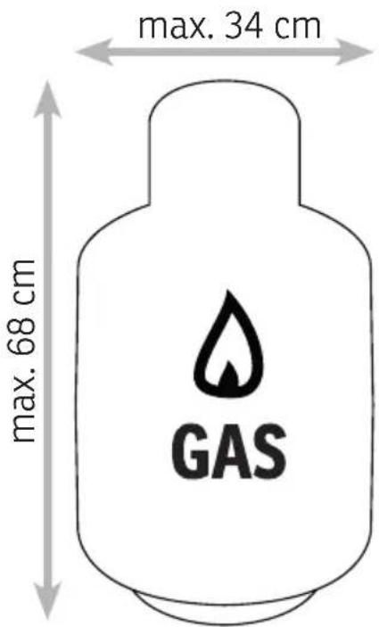
max. 34 cm max. 68 cm GASThe gas connections are tested for tightness in the factory before delivery. A complete leak test must be carried out at the installation site after installation.
During the test, no heat and fire sources can be present in the vicinity of the device!
- Mix a soap solution of one part liquid cleaner and one part water. The soap solution can be applied with a spray bottle, brush or cloth. In case of a leak, soap bubbles will form.
- The heater must be checked with a full gas bottle.
- Make sure that the regulator is set to OFF.
- Turn the gas supply completely on.
06 - CONTROL

text_image
Igniter Piezo ignition generates sparks in the burner when pressed. Regler Drehen, um die Flamme zu regulieren. Drücken, um die Gaszufuhr zu öffnen (Pilot). Important: Insert battery before start-up. The entire ignition knob can be turned up counterc-lockwise, underneath is the battery compartment for the ignition. High Maximum gas supply. Strong flame in the burner. Low Minimal gas supply. Weak flame in the burner. Off Gas supply completely interrupted. No flame in the burner. Pilot Gas supply only when regulator is pressed. OFF: The heating turns off LO: Minimum temperature HI: Maximum temperatureImportant: When using for the first time or after replacing a gas cylinder in step 2, wait at least 60 seconds to remove air from the lines.
- Turn the valve of the gas bottle fully open.
- Press the gas regulator and turn it to the pilot position.
- Press and hold the gas control knob for 30 seconds while operating the ignition several times until the pilot flame lights up.
- Turn the gas control knob to the High position. Hold this setting for at least 5 min.
- Then turn the gas control knob to the desired heating power.
Switch off
- Turn the knob to the PILOT position.
- Press and turn the knob to the OFF position.
- Turn the valve on the gas cylinder fully.
text_image
100 cm 100 cmMinimum safety distance
- The heater is primarily for outdoor use only. Always ensure that there is sufficient fresh air supply.
- Always maintain the prescribed distance from combustible materials: at least 100 cm at the top and at least 100 cm at the sides.
• Phoenix must be placed on solid, level ground. - Never use the heater in explosive environments, such as areas
- environment, such as in areas where gasoline or other flammable liquids or gases are stored.
08 - CLEANING, CARE AND MAINTENANCE
Storage
Before you store the device, make sure that the gasvalve is completely closed and the pressure regulator disconnected from the gastank. Only put the protection hood on, when device has cooled.
Cleaning
Clean coated surfaces with a soft, damp cloth. Never clean the heater with flammable or caustic cleaning agents. Make sure that the burner is cleaned regularly. Insects can get caught in the burner housing and burn during operation.
Maintenance
Perform a leak test after a longer period of non-use. If there is any damage to the technology, do not use the device and contact customer service.
09 - TECHNICAL DETAILS
Construction properties
- Transportable patio and garden heater with tank housing
- Housing made of steel with powder coating or stainless steel
• Gas hose connections with metal clamp - Heat emission reflector
Technical properties
- Only use propane or butane gas
• Max.Wattage:13kW - Min Wattage: 5 kW
Table of the injector
| Gas category | 3+ (28 - 30/37) | 3B/P(30) | 3 B/P (50) | 3B/P(37) | |
| Gas-Types Butane | Propane | LPGGasmixture | LPGGasmixture | LPGGasmixture | |
| Gas pressure | 28 - 30 mbar | 37 mbar | 29 mbar | 50 mbar | 37 mbar |
| Total heat input:(HS): (QN) | 13 kW (Butan: 945 g/h • Propan 928 g/h) | ||||
| Injector Size | |||||
| 1.88 mm to Main burner0.18 mm to Pilot burner | 1.55 mm to Main burner0.18 mm to Pilot burner | 1.65 mm to Main burner0.18 mm to Pilot burner | |||
| The mark on the injector (e.g. 1.88) indicates that the size of the injector is 1.88 mm | |||||
Warranty
All products are checked from our company before the delivery. In case that there is a lack on your product, please contact the vendor. Please bring your proof of purchase for guarantees. Please save the packaging materials of the unit.
Disposal
Please remove the heater properly. You can bring the product to any specialist dealer fort he removal.
Technical changes
Technical changes in technique and design are possible.
CE declaration of Conformity
This device complies with the following standards
EWR EN 14543:2017
EWR 2016/426
| PROBLEM Possible reason Solution | ||
| Pilot flame is not lit. | - Gas valve may be switched off- Gas bottle is empty- Opening is blocked- Connection lost | - Turn on the gas valve- Connect a new gas cylinder- Clean from any dirt- Check the connections |
| Pilot flame does not stay on. | - Dirt around the fire source- Loose connections- Gas leak in hose- Lack of fuel pressure | - Clean the dirty places- Check the connections- Replace the hose- Connect a new gas cylinder |
| Burner does not burn. | - Pressure is too low- Dirt around the fire source | - Connect a new gas cylinder- Clean from any dirt |
Any modifications or repairs to the device must be carried out by a qualified person.
Since the development of the produced devices is constantly progressing, your product may differ minimally from the one described.
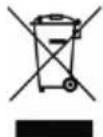
DISPOSAL INSTRUCTIONS FOR THE ELECTRICAL PART OF THE PRODUCT
In accordance with Article 26 of the Decree-Law of 14 March 2014 implementing Directive 2012/19/EC, and the Law of 31 March 2015 implementing Directive 2015/863/EU on the reduction of the use of hazardous substances in electrical and electronic equipment and on waste management.
The crossed-out dustbin symbol on the machine or packaging indicates that the waste generated at the end of its useful life must be collected separately from other waste. The user must therefore take the device to the appropriate collection points at the end of its service life. Sort electronic and electrical waste or send back to the retailer when purchasing new, equivalent devices in a one-to-one process. Appropriate separate collection for subsequent commissioning of the equipment to be recycled, treatment and environmentally sound disposal helps to avoid possible adverse effects on the environment and health, and promote the reuse and/or recycling of the materials to which they belong. Misuse of this product by the user will result in the application of the administrative penalties provided for in the applicable legislation. Batteries contained in the device must be disposed of separately in the appropriate containers for the collection of used batteries.

DISPOSAL OF BATTERIES AND ACCUMULATORS
In accordance with Legislative Decree 188 of 20 November 2008 implementing Directive 2006/66/EC on batteries, accumulators and related waste, the symbol of the crossed-out waste bin on the battery indicates that the disposal of used batteries is prohibited in household waste.
Single-use and rechargeable batteries contain substances that are highly polluting for the environment. The user is obliged to dispose of used batteries at collection points in the municipality or in appropriate containers. This service is free. In this way, legal requirements are adhered to and the environment protected. The symbols identifying hazardous materials that may be present in single-use and rechargeable batteries are as follows: Hg = Mercury, Cd = Cadmium, Pb = Lead.