
CLUB-WHITE450-IP - Light projector AFX - Free user manual and instructions
Find the device manual for free CLUB-WHITE450-IP AFX in PDF.

| Product type | Light projector |
| Brand | AFX |
| Model | CLUB-WHITE450-IP |
| Protection rating | IP65 |
| Light source | 4 LED COB warm/cool white 50W |
| Dimensions (L x H x D) | 299 x 155 x 279 mm |
| Weight | 4.75 kg |
| Power supply | 100-240 V~, 50/60 Hz |
| Power consumption | 280 W |
| Operating modes | Automatic, DMX, Master-Slave, Music control, IR remote |
| DMX channels | 7 or 15 channels (selectable) |
| Color control | Warm white and cool white separately controllable |
| Remote control | Infrared, CR2025 battery included |
| Minimum lighting distance | 0.5 m |
| Minimum distance from surfaces | 50 cm |
| Maximum ambient temperature | 40 °C |
| Protection class | I (earthing required) |
| Power connectors | SEETRONIC waterproof (Power In/Out) |
| Mounting | Extra-large bracket, screw holes |
| Maintenance | Clean with glass cleaner and soft cloth, annual internal vacuuming |
| Repairability | Non-replaceable light source, repair by authorized professional |
| Recycling | Do not dispose of with household waste |
| Package contents | Device, IR remote, power cord, XLR cable, manual |
Frequently Asked Questions - CLUB-WHITE450-IP AFX
User questions about CLUB-WHITE450-IP AFX
0 question about this device. Answer the ones you know or ask your own.
Ask a new question about this device
Download the instructions for your Light projector in PDF format for free! Find your manual CLUB-WHITE450-IP - AFX and take your electronic device back in hand. On this page are published all the documents necessary for the use of your device. CLUB-WHITE450-IP by AFX.
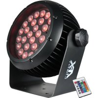
USER MANUAL CLUB-WHITE450-IP AFX
PAR PROJECTOR 4 X 50W WARM & COLD
WHITE COB LED WITH INDIVIDUAL LED
CONTROL - IP65
PROJECTEUR PAR A LED COB BLANC CHAUD/
| Mode/Channel | Value | Function | |
| CH15 | CH07 | ||
| 1 | 1 | Dimmer | |
| 0..255 | Dimmer 0%...100% | ||
| 2 | 2 | Shutter | |
| 0..31 | Shutter closed | ||
| 32..63 | shutter open | ||
| 64..95 | Strobe effect slow to fast | ||
| 96..127 | shutter open | ||
| 128..159 | Pulse-effect in sequences slow to fast | ||
| 160..191 | shutter open | ||
| 192..223 | Random strobe effect slow to fast | ||
| 224..255 | shutter open | ||
| 3 | 3 | Warm White | |
| 0..255 | 0-100% Warm White dimmer from dark to bright | ||
| 4 | 4 | Cold White | |
| 0..255 | 0-100% Cold White dimmer from dark to bright | ||
| 5 | 5 | Color Temp | |
| 0..15 | No Function | ||
| 16..45 | Below 3200K | ||
| 46..75 | 3200K - 3500K | ||
| 76..105 | 3500K - 5000K | ||
| 106..135 | 5000K - 5500K | ||
| 136..165 | 5500K - 6000K | ||
| 166..195 | 6000K - 6500K | ||
| 196..225 | 6500K - 7000K | ||
| 226..255 | 7000K - 8000K | ||
| 6 | 6 | Macro RUN | |
| 0..15 | No function | ||
| 16..27 | Macro Run 1 | ||
| 28..39 | Macro Run 2 | ||
| 40..51 | Macro Run 3 | ||
| 52..63 | Macro Run 4 | ||
| 64..75 | Macro Run 5 | ||
| 76..87 | Macro Run 6 | ||
| 88..99 | Macro Run 7 | ||
| 100..111 | Macro Run 8 | ||
| 112..123 | Macro Run 9 | ||
| 124..135 | Macro Run 10 | ||
| 136..147 | Macro Run 11 | ||
| 148..159 | Macro Run 12 | ||
| 160..171 | Macro Run 13 | ||
| 172..183 | Macro Run 14 | ||
| 184..195 | Macro Run 15 | ||
| 196..207 | Macro Sound 1 | ||
| 208..219 | Macro Sound 2 | ||
| 220..231 | Macro Sound 3 | ||
| 232..243 | Macro Sound 4 | ||
| 244..255 | Macro Sound 5 | ||
| 7 | 7 | Macro Speed | |
| 0..255 | Macro Speed from Slow To Fast | ||
| 8 | Warm White of Led 1 | ||
| 0..255 | 0-100% Warm White of Led 1 dimmer from dark to bright | ||
| 9 | Cold White of Led 1 | ||
| 0..255 | 0-100% Cold White of Led 1 dimmer from dark to bright | ||
| 10 | Warm White of Led 2 | ||
| 0..255 | 0-100% Warm White of Led 2 dimmer from dark to bright | ||
| 11 | Cold White of Led 2 | ||
| 0..255 | 0-100% Cold White of Led 2 dimmer from dark to bright | ||
| 12 | Warm White of Led 3 | ||
| 0..255 | 0-100% Warm White of Led 3 dimmer from dark to bright | ||
| 13 | Cold White of Led 3 | ||
| 0..255 | 0-100% Cold White of Led 3 dimmer from dark to bright | ||
| 14 | Warm White of Led 4 | ||
| 0..255 | 0-100% Warm White of Led 4 dimmer from dark to bright | ||
| 15 | Cold White of Led 4 | ||
| 0..255 | 0-100% Cold White of Led 4 dimmer from dark to bright | ||
USER MANUAL
FEATURES
- 4x 50W cold/warm white COB LED
- Separate control of the 4 LEDs
7/15 DMX channels - Auto, DMX, master-slave, music and remote-controlled operation
- IR remote control included
- Protection glass
- Waterproof SEETRONIC connectors
- Extra-large bracket
IP65
EXPLANATION OF SYMBOLS

The triangle containing a lightning symbol is used to indicate whenever your health is at risk (due to electrocution, for example).

An exclamation mark in a triangle indicates particular risks in handling or operating the appliance.

The unit complies with UK standards

Protection class I. Requires an earth connection

Minimum distance between the appliance and other objects

Don't stare into the light beam

CAUTION DO NOT OPEN THE HOUSING SHOCK HAZARD
SAFETY RECOMMENDATIONS
-
Please read these instructions carefully, they include important information about the installation, usage and maintenance of this product.
-
Please keep this User Guide for future reference.
- Always make sure that you are connecting to the proper voltage, and that the line voltage you are connecting to is not higher than that stated on the bottom of the fixture.
- The appliance is part of class I and must exclusively connected to an earthed mains outlet.
- Make sure there are no flammable materials close to the unit while operating.
- The unit must be installed in a location with adequate ventilation, at least 20in (50cm) from adjacent surfaces. Be sure that no ventilation slots are blocked.
The minimum distance luminaire from that part of the luminaire or lamp to the lighted object is 0.5m - The max. ambient temperature (Ta) is 40°C . Don't operate the fixture at higher temperatures.
- During operation the housing might get very hot. DO NOT OPEN the device within 20 minutes after switching off.
- In the event of a serious operating problem, stop using the unit immediately. Never try to repair the unit by yourself. Repairs carried out by unskilled people can lead to damage or malfunction. Please contact the nearest authorized technical assistance center. Always use the same type of spare parts.
- Make sure the power cord is never crimped or damaged.
- Avoid direct eye exposure to the light source while it is on as sensitive persons may suffer an epileptic shock (especially meant for epileptics)!
The product is for decorative purposes only and not suitable as a household room illumination. - If the external flexible cable or cord of this luminaire is damaged, it shall be exclusively replaced by the manufacturer or his service agent or a similar qualified person in order to avoid a hazard
- The lenses, housing or ultraviolet filter must be replaced if they are visibly damaged.
- Please note that the lamp of this device cannot be replaced. If the lamp is faulty, the unit must be discarded
DISCONNECT DEVICE
Please note that the unit DOES NOT have an ON/OFF switch. Please unplug the unit to remove complete the power from the internal circuits before cleaning or servicing. Therefore, the disconnect device shall remain readily accessible.
FUSE REPLACEMENT
Disconnect the power cord before replacing a fuse and always replace with the same type fuse.
With a screwdriver wedge the fuse holder out of its housing.
Remove the damaged fuse from its holder and replace with exactly the same type of fuse.
Insert the fuse holder back in its place and reconnect power.
Warning: If after replacing the fuse you continue to blow fuses, STOP using the unit. Contact customer support for further instructions. Continuing to use the unit may cause serious damage.
FIXTURE LINKING (FIG4)
You will need a serial data link to run light shows of one or more fixtures using a DMX-512 controller or to run synchronized shows on two or more fixtures set to a master/slave operating mode. The combined number of channels required by all fixtures on a serial data link determines the number of fixtures that the data link can support.
Important: Fixtures on a serial/data link must be daisu chained in one single line.
DATA CABLING
To link fixtures together you must use data cables. If you choose to create your own cable, please use data-grade cables that can carry a high quality signal and are less prone to electromagnetic interference.
DMX CONNECTOR CONFIGURATION
Termination reduces signal errors. To avoid signal transmission problems and interference, it is always advisable to connect a DMX signal terminator.
INSTALLATION (FIG.3)
The unit should be mounted via its screw holes on the bracket. Always ensure that the unit is firmly fixed to avoid vibration and slipping while operating. Always ensure that the structure to which you are attaching the unit is secure and is able to support a weight of 10 times of the unit's weight.
The installation must always be secured with a secondary safety attachment, e.g. an appropriate safety rope. Never stand directly below the device when mounting, removing or servicing the fixture. This fixture may be mounted in any position provided there is adequate room for ventilation.
When mounting this fixture on a truss, be sure to use an appropriate clamp. As an added safety measure, be sure to attach at least one properly rated safety cable to the fixture.
POWERLINK
Connect a SEETRONIC cable from the POWER OUT connector of the 1st unit to the POWER IN connector of the second unit, etc.
CONTROL PANEL (FIG. 2)
To access the main menu press the MENU button. Press the UP or DOWN buttons until you reach function you wish to change. When you reach the function you wish to change, press the ENTER button. When a function is selected, use the UP or DOWN buttons to change the function settings. Once your changes are made, press the ENTER button.
Check the following function table :
| MENU DESCRIPTION | |||||
| MODE | ADDR | VALU A001~A XXX (AAAA) DMX address setting | |||
| SLAV Slave setting | |||||
| AUTO IP1-15 | ALON /(AU-A) | SP_1~SP_5 (Speed) Auto-run (Master) | |||
| MAST /AU-M) | |||||
| SOUN IP1-5 | ALON (SO-A) Sound control (alone) | ||||
| MAST/(SO-M) Sound control (Master) | |||||
| SET | MIC M-XX Mic sensitivity setting | ||||
| LOAD ON/OFF | Reload data | ||||
| VER | V-2.0 | Software version | |||
| CALI | Code (password: 088) | Input password | |||
| CH03-CH04 | Calibration | ||||
| FREQ | Low/High | PWM Frequency setting | |||
| DMX | CH07 | 7CH | |||
| CH15 | 15CH | ||||
| REST ON/OFF | Reset to factory default | ||||
| MANU | WXXX | C000-255 | Warm dimmer | ||
| CXXX | C000-255 | Cold dimmer | |||
| TEMP | TXXX | Current temperature | |||
DMX channel chart: please refer to page 3-4
IR REMOTE CONTROLLER
Please operate the remote control within a distance of 6m and 30° between the remote and the appliance. Aim the remote at the sensor. Remove all obstacles between the remote and the sensor.
The remote control might not work properly if the sensor is exposed to strong sunshine.
If the remote control doesn't work properly, please check the batteries.
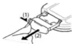
INSTALLING THE BATTERIES IN THE REMOTE CONTROL
- Place the remote face down on a flat surface.
- Push the compartment cover into the direction of the arrow.
- Slide the battery compartment open.
- Remove the old battery and install the new one (CR2025) with the plus (+) symbol facing up.
Gently slide the battery compartment closed. It locks automatically.
RECOMMENDATIONS FOR BATTERIES

This symbol indicates that used batteries should not be disposed of with household waste but deposed correctly in accordance with your local regulations..
Batteries shall not be exposed to excessive heat such as sunshine, fire or the like.
When the internal batteries are not to be used, remove them to avoid damage caused by battery leakage or corrosion.
ATTENTION: Danger of explosion if battery is incorrectly placed. Only replace by the same or equivalent type.
WARNING : Do not swallow the battery. Danger of chemical burns. Keep new and old batteries out of the reach of children.
If the battery compartment doesn't close properl, stop using the product and keep it out of the reach of children.
If you are in doubt whether the batteries have been swallowed or introduced into any other part of the body, contact immediately a doctor.
REMOTE CONTROL
NOTE: PLEASE SET THE UNIT TO MODE -> ADDR, OTHERWISE THE REMOTE CONTROL WILL NOT WORK
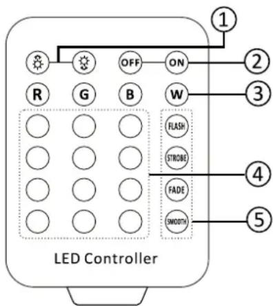
- BRIGHTNESS & SPEED adjustment: Press or to set the brightness and speed in programme mode
- ON/OFF of the LEDs.
- SELECT BASIC COLOR:
R:Warm white
G: cool white
B: warm white + cool white
W: warm white + cool white
- COLOUR BUTTONS: Press one of the 12 colour buttons to select a built-in programme.
CLEANING AND USING FREQUENCY OF PRODUCT
Please make sure that the light is power off before dismantling or maintaining, it's very important to keep the light clean. Frequent cleaning will ensure maximum brightness output, but also prolong the life time. It's suggested to use the high quality, professional glass detergent and soft cloth to clean the light. It's not allowed to use alcohol or chemical solvent.
When the light doesn't work, please check if the fuse is burnt out or not. If it is, the same fuse should be replaced, find out the faulty and restart the light. But please note the repair must be handled by professional.
TECHNICAL SPECIFICATIONS
Power Supply 100-240V~50/60Hz
Consumption 280W
Light source .4x50W CW/WW COB LED
Dimensions 299 x 155 x 279mm
Weight 4.75kg

IMPORTANT NOTE: Electric products must not be put into household waste. Please bring them to a recycling centre. Ask your local authorities or your dealer about the way to proceed.
MANUEL D'UTILISATION
DESCRIPTION
DISPOSITIF DE COUPURE
INSTALLATION (FIG. 3)
R:Warmweiss
G: Kaltweiss
B:Warmweiss + Kaltweiss
W:Warmweiss + Kaltweiss

View the item on our website

AFXLIGHTPRO
Follow us on Instagram

Any problem or question? Join us on facebook
CE
UK CA
A DEPOSER EN MAGASIA
A DEPOSER EN DECHETERIE

Designed by LOTRONIC S.A.
Rue F. Englert 17 • Bt 2
B-1480 Tubize
Copyright LOTRONIC 2024
- USER MANUAL
- FEATURES
- EXPLANATION OF SYMBOLS
- SAFETY RECOMMENDATIONS
- DISCONNECT DEVICE
- FUSE REPLACEMENT
- FIXTURE LINKING (FIG4)
- DATA CABLING
- DMX CONNECTOR CONFIGURATION
- INSTALLATION (FIG.3)
- POWERLINK
- CONTROL PANEL (FIG. 2)
- IR REMOTE CONTROLLER
- INSTALLING THE BATTERIES IN THE REMOTE CONTROL
- RECOMMENDATIONS FOR BATTERIES
- REMOTE CONTROL
- NOTE: PLEASE SET THE UNIT TO MODE -> ADDR, OTHERWISE THE REMOTE CONTROL WILL NOT WORK
- CLEANING AND USING FREQUENCY OF PRODUCT
- TECHNICAL SPECIFICATIONS
- MANUEL D'UTILISATION
- DESCRIPTION
- DISPOSITIF DE COUPURE
- INSTALLATION (FIG. 3)
Brand : AFX
Model : CLUB-WHITE450-IP
Category : Light projector