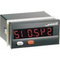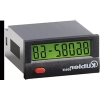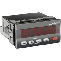
Codix 566 - Controller Kübler - Free user manual and instructions
Find the device manual for free Codix 566 Kübler in PDF.


User questions about Codix 566 Kübler
0 question about this device. Answer the ones you know or ask your own.
Ask a new question about this device
Download the instructions for your Controller in PDF format for free! Find your manual Codix 566 - Kübler and take your electronic device back in hand. On this page are published all the documents necessary for the use of your device. Codix 566 by Kübler.
USER MANUAL Codix 566 Kübler
for Strain Gauge inputs with Totaliser function
SELV,CLASS II (Limited
Power Source)
for Strain Gauge inputs with Totaliser function
Order code
6.56X.X1X.X0X
Further outputs (optional)
0 = none
9 = analogue output
(only for DC version)
Supply voltage
0 = 100 240VAC± 10%
3 = 10 30VDC
Outputs
0 = Relays
Front
0 = Kübler version
A = Neutral version
Input type
4 = Temperature
5 = Analogue
6 = Strain-gauge
Table of Contents (German is the original version.)
1 Preface 3
2 Safety instructions andWarnings 3
2.1 Use according to the intended purpose 3
2.2 Mounting in a control panel 3
2.3 Electrical Installation 4
2.4 Cleaning and maintenance 4
3 Description 5
4 Display/Operating elements 5
5 Block diagram 6
6 Connections 6
7 Operating concept (Operating mode) 7
8 Programming 8
9 Function Groups 10
9.1Help Texts (running text) 10
9.2 Signal inputs 10
9.3 User Linearisation 11
9.4 Function Multifunction Key (MP-Key) and Multifunction inputs (MP-INP) 13
9.4.1 Multifunction Key 14
9.4.2 Multifunction Inputs 14
9.5 Totaliser function 15
9.6 Limit Value (Alarm) Monitoring 16
10 Monitoring of Measuring Circuit 18
11 Technical Data
11.1 General Data 19
11.2 Measuring signal inputs 19
11.3 Control Inputs MPI 1 / MPI 2 19
11.4 Alarm outputs 19
11.5 Supply voltage 19
11.6 Sensor supply voltage 19
11.7 Climatic Conditions 19
11.8 EMC 19
11.9 Device Safety 19
11.10 Mechanical Data 19
11.11 Connections 20
12 Dimensional Drawings 20
13 Help Texts 21
1 Preface

Please read this instruction manual entirely and carefully before installation and start-up. Please observe all warnings and advice, both for your own safety and for general plant safety. If the device is not used in accordance with this instruction manual, then the intended protection can be impaired.
2 Safety instructions andWarnings

Please use the device only if its technical condition is perfect. It should be used only for its intended purpose. Please bear in mind safety aspects and potential dangers and adhere to the operating instructions at all times. Defective or damaged devices should be disconnected from the mains immediately and taken out of operation.
The device shall not be opened. Use the repair service of the manufacturer.
Only connect the device to the electricity networks provided to that purpose.
The safety of the system in which the device is integrated is the responsibility of the installer.
Disconnect all electricity networks prior to any installation or maintenance work.
Use exclusively cables approved in your country and designed for your temperature and power ranges.
Installation and service work shall be carried out exclusively by qualified personnel.
The device must compulsorily be protected with approved external fuses. The value of these fuses can be found in the technical information.
| ! | This symbol is used on the device to remind of the existence of dangers, which are referred to in this manual. |
| ! | This symbol is used on the device to remind of the existence of dangers, which are referred to in this manual. |
2.1 Use according to the intended purpose
The purpose of the Process Control devices is to display measured values, as well as to monitor limit values (alarms). The application areas for this device lie in industrial processes and controls.
The application area for this device lies in industrial processes and controls, in the fields of manufacturing lines for the metal, wood, plastics, paper, glass, textile and other like industries. Overvoltages at the terminals of the device must be kept within the limits of Over-voltage Category II. The device must only be operated when mounted in a panel in the correct way and in accordance with the section "Technical Data".
The device is not suitable for use in hazardous areas and for areas excluded in EN 61010 Part 1. If the device is used to monitor machines or processes in which, in the event of a failure of the device or an error made by the operator, there might be the risk of damaging the machine or causing an accident to the operators, it is your responsibility to take the appropriate safety measures.
The device has been designed for indoor operation. It may nevertheless be used outdoors, provided the technical data is adhered to. In this case, take care to provide suitable UV protection.
2.2 Mounting in a control panel

Mount the device away from heat sources and avoid direct contact with corrosive liquids, hot steam or similar.
CAUTION
Provide a free space of 10mm all around the device for its ventilation.
The device should be mounted so that the terminals are out of the reach of the operator and cannot be touched by him. When mounting the device, consider the fact that only the front side is classified as accessible for the operator.
Mounting instructions
- Remove the mounting clip from the device.
- Insert the device from the front into the panel cut-out, ensuring the front-panel gasket is correctly seated.
- Slide the fixing clip from the rear onto the housing, until the spring clamps are under tension and the upper and lower latching lugs have snapped into place.
Note: In case of proper installation, IP65 can be reached on the front side.
2. 3 E I e c t r

DANGER
The device must be disconnected from any power supply prior to any installation or maintenance work. Make sure that no more voltages IABLE TO CAUSE AN ELECTROCUTION are present.
AC-powered devices must only be connected to the low-voltage network via a switch or circuit breaker installed close to the device and marked as their disconnecting device.
Installation or maintenance work must only be carried out by qualified personnel and in compliance with the applicable national and international standards.
Take care to separate all extra-low voltages entering or exiting the device from hazardous electrical conductors by means of a double or reinforced insulation (SELV circuits).

DANGER
The device must be protected externally for its proper operation. Information about the prescribed fuses can be found in the technical information.
The relay outputs are not protected internally in the device. Without suitable protection of the relay outputs, undesired heat development or even fire may occur. The relay outputs must be protected externally by the manufacturer of the plant. It must also be made sure that, even in case of a malfunction, the values stated in the technical data are under no circumstances exceeded.
- During installation, make sure that the supply voltage and the wiring of the output contacts are both fed from the same mains phase, in order not to exceed the maximum permitted voltage of 250V .
- The cables and their insulation must be designed for the planned temperature and voltage ranges. Regarding the type of the cables, adhere to the applicable standards of the country and of the plant. The cross sections allowed for the screw terminals can be found in the technical data.
Before starting the device installation, proper wiring and tightening. The screws of unused screw terminals must be screwed to the stop, so that they cannot loosen and get lost.
- The device has been designed for overvoltage category II. If higher transient voltages cannot be excluded, additional protection measures must be taken in order to limit the overvoltage to the values of CAT II.
Advice on noise immunity
All connections are protected against external sources of interference. The installation location should be chosen so that inductive or capacitive interference does not affect the device or its connecting lines! Interference (e.g. from switchmode power supplies, motors, clocked controllers or contactors) can be reduced by means of appropriate cable routing and wiring.
Measures to be taken:
- Use only shielded cable and control lines. Connect shield at both ends. The conductor cross-section of the cables should be a minimum of 0.14mm^2
- The shield connection to the equipotential bonding should be as short as possible and with a contact area as large as possible (low-impedance).
- Only connect the shields to the control panel, if the latter is also earthed.
- Install the device as far away as possible from noise-containing cables.
- Avoid routing signal or control cables parallel to power lines.
2.4 Cleaning and maintenance
The front side of the unit should only be cleaned using a soft damp (water!) cloth. Cleaning of the embedded rear side is not planned and is the responsibility of the service personnel or of the installer.
In normal operation, this device is maintenance-free. Should the device nevertheless not operate properly, it must be sent back to the manufacturer or to the supplier. Opening and repairing the device by the user is not allowed and can adversely affect the original protection level.
3 Description
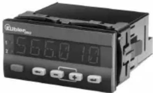
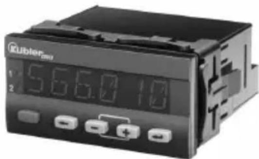
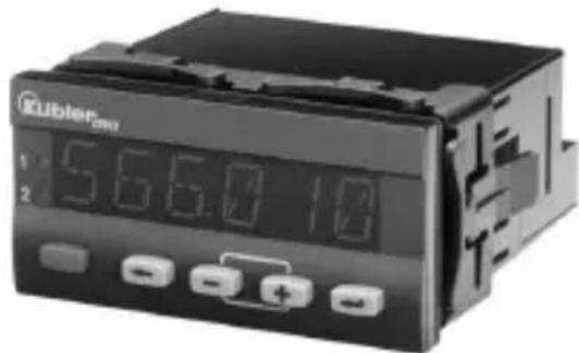
Digital panel meter for displaying measured values, as well as monitoring limit values in industrial applications.
- 6-digit 14-segment LED display, 14 mm ,for displaying measured values and dialogs
- Running text can be switched on as Help Text
Language for the Help Text selectable as English or German - Signal input for strain gauges 3.3mV/V,3.0mV/V,2.0mV/V,1.5mV/V and 1.0mV/V
- Sampling rate 10 readings per second
- Digital filter (1st order) for smoothing display fluctuations with unstable input signals
- Customised linearisation
MIN/MAX memory function - Manually-controlled Totaliser function
- 2 Relay outputs (changeover contacts) for limit monitoring
- Start delay for relay outputs after Power ON
- Versions for supply voltage 10 ... 30 V DC and 100 ... 240 V AC ± 10%
- Excitation supply 10VDC / 30mA for powering 350 bridges
Additional aux. power output 24V / 30mA with AC supply - Programmable via the front keys
- Multifunction key and two multifunction inputs, function programmable
7 Operating concept (Operating mode)
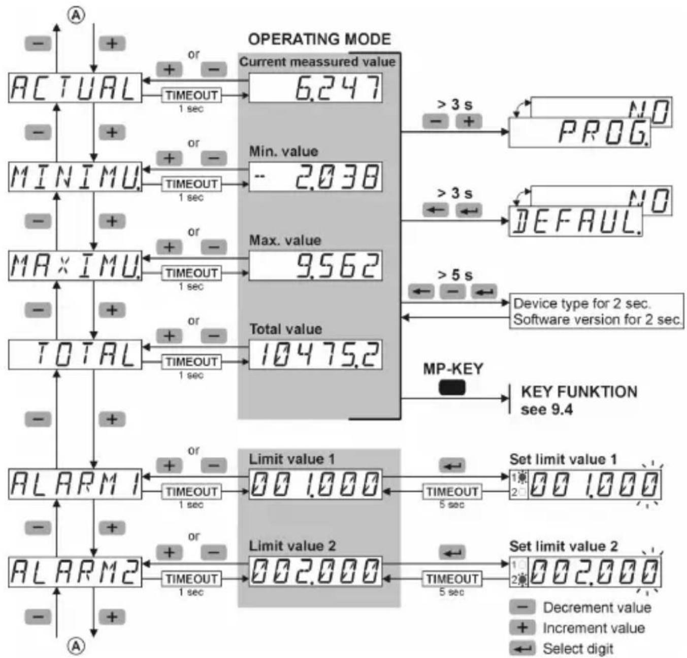
To enter the Programming menu


- During programming the relays are inactive (not energised).
- When quitting the programming menu via SAVE, the minimum and maximum values and the totaliser value are all cleared.
Entering the Programming Menu / Selecting Function Group / Quitting the Programming menu
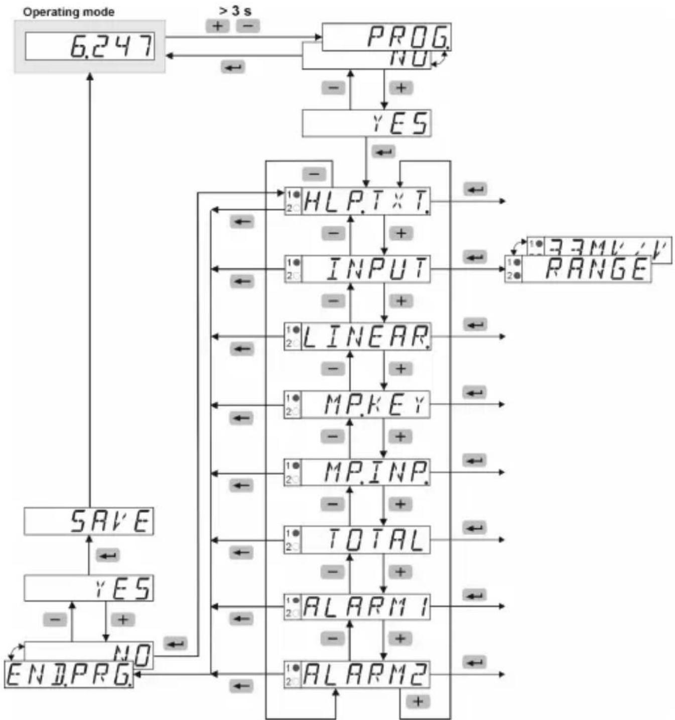
Selecting Function / Setting Parameters / Accepting Parameters
Function Groups Function Parameter
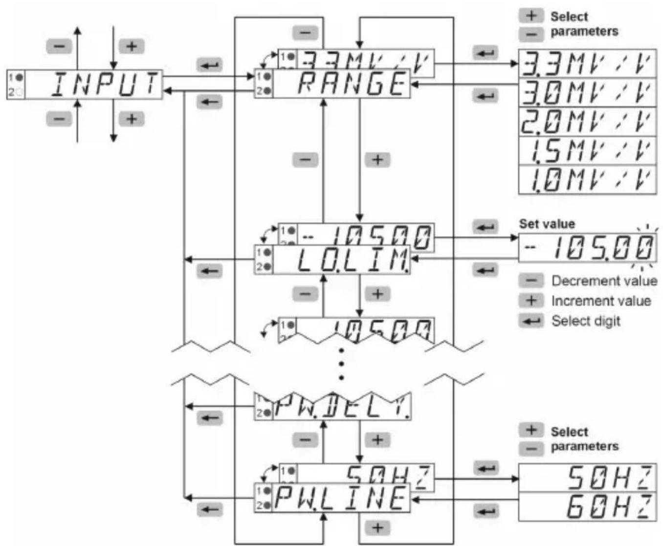
9 Function Groups

Factory settings are highlighted grey
9.1 Help Texts (running text)
| HLPT×T | Help Text menu |
| HLPT×T | Select Help Text |
| ON | ON - a running text that has started can be aborted with any programming key OFF |
| OFF | |
| SLLANG | Select language for Help Text |
| EN | English |
| DE | Deutsch (German) |
9.2 Signal inputs
| INPUT | Menu Input Signal |
| RANGE | Select measuring range |
| 3.3MV/√V | Sensitivity 3.3 mV/V |
| 3.0MV/√V | Sensitivity 3.0 mV/V |
| 2.0MV/√V | Sensitivity 2.0 mV/V |
| 1.5MV/√V | Sensitivity 1.5 mV/V |
| 1.0MV/√V | Sensitivity 1.0 mV/V |
| LOLIM | Select lower measuring range limit |
| -105.00 | Input range 0.00 ... -105.00 [%] |
| HILIM | Select upper measuring range limit |
| 105.00 | Input range 0.00 ... +105.00 [%] |
| IP | Select decimal point (optical function only) |
| 0.00 | 0 0.0 0.00 0.000 0.0000 |
| INPLO | Select input low value |
| -100.00 | Input range -105.00 ... +105.00 [%] |
| DISPLO | Select display low value for INP.LO. |
| -100.00 | Input range -199999 ... +999999 and DP |
| INPHI | Select input high value |
| 100.00 | Input range -105.00 ... +105.00 [%] |
| DISPHI | Select display high value for INP.HI. |
| 100.00 | Input range -199999 ... +999999 and DP |
| FILTER | Select Input Filter The Filter function shows how many measurement cycles are used to determine the moving average. |
| 1 | Input range 1 ... 99 [cycles] - with a value of 1 the filter function is switched off |
| PHJELY | Select Start Delay after Power On (limit monitoring is processed only after the programmed time has expired) |
| 00 | Input range 0.0 ... 99.9 [sec] |
| PHFREQ | Select local mains frequency |
| SBHZ | Mains frequency 50 Hz |
| 60HZ | Mains frequency 60 Hz |

The input range for the input values is entered in % . This means that with a sensor voltage of 10V and a sensor sensitivity of 3.3mV / V then 33mV equate to an input value of 100%
The functions LO.LIM and HI.LIM limit the editable range.
The value for HI.LIM must always be greater than the value for LO.LIM.
9.3 User Linearisation
| LINEAR | Menu User Linearisation |
| LINEAR | Select User Linearisation |
| NO | Linearisation OFF |
| YES | Linearisation ON |
| NUMPNT | Select number of linearisation(control) points |
| 3 | Input range 3 ... 12 |
| INPLC | Select input low value |
| -100.00 | Input range-105.00 ... +105.00 [%] |
| DISPLC | Select display low value for INP.LO. |
| -100.00 | Input range-199999 ... +999999 and DP |
| INP.OI | Select input value 1 |
| 8.00 | Input range-105.00 ... +105.00 [%] |
| DISPL | Select display value for INP.01. |
| 8.00 | Input range-199999 ... +999999 and DP |
| A maximum of 12 linearisation points is possible.An input value INP must be entered for eachlinearisation point (LP) - input of the sensorvalue from the analogue input in physical units -as well as the corresponding display value DISPfor this sensor value. The linearisation points(LP) may be entered in any order. They are thensorted in the firmware in ascending order for thenegarisation function. Linearisation based on a negative slope is possible. | |
| INP.10 | Select input value 10 |
| 8.00 | Input range-105.00 ... +105.00 [%] |
| DISPL.10 | Select display value forINP.10. |
| 8.00 | Input range-199999 ... +999999 and DP |
| INPHI | Select input high value |
| 100.00 | Input range-105.00 ... +105.00 [%] |
| DISPHI | Select display high value forINP.HI. |
| 100.00 | Input range-199999 ... +999999 and DP |
The input range for the input values is entered in % . This means that with a sensor voltage of 10V and a sensor sensitivity of 3.3mV / V then 33mV equate to an input value of 100%
The functions LO.LIM and HI.LIM limit the editable range.
The value for HI.LIM must always be greater than the value for LO.LIM.
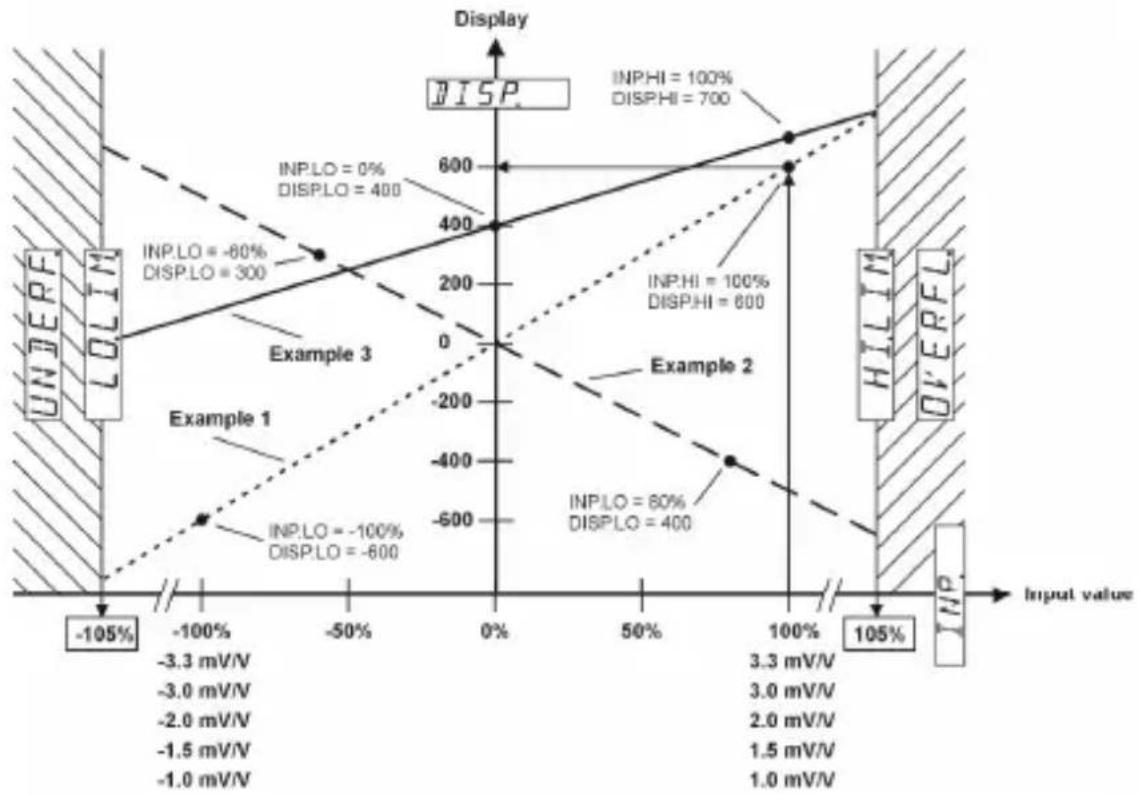
Example for linear scaling
Example 1: -100 % ... +100 % = -600 ... 600
Example 2: -60%...+80%=300...-400
Example 3: 0% +100% = 400 700
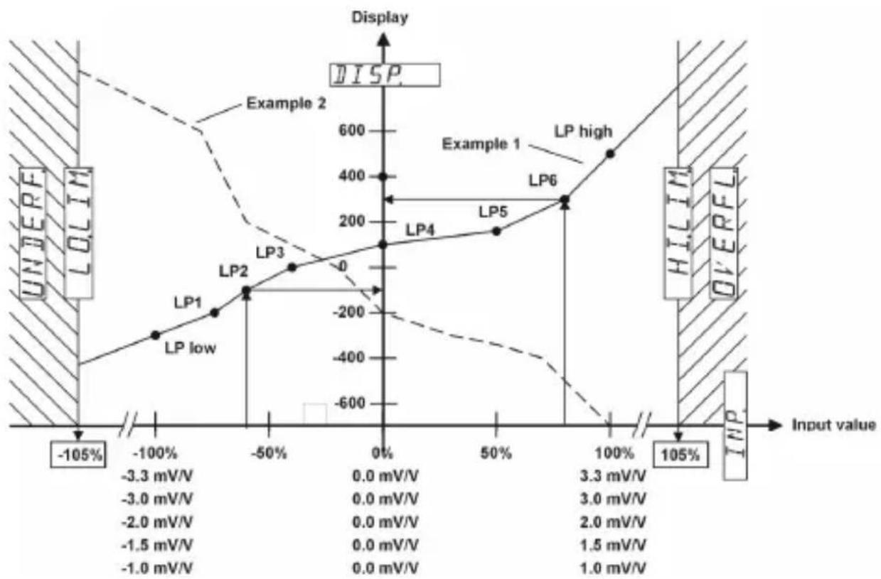
Example for non-linear scaling
9. 4 F u n c t i (MP-Key) and Multifunction inputs (MP-INP)
Tare
- In the function group MP_KEY, programme the function TARA to ON. In the operating mode select the current measured value (ACTUAL) and briefly press the MP Key.
- In the function group MP.INP, programme the function MP.INP1 or MP.INP2 to TARA. In the operating mode briefly activate the multifunction input 1 or multifunction input 2.
Reset Tare Value
- In the function group MP_KEY, programme the function TARA to ON. In the operating mode select the current measured value (ACTUAL) and press the MP Key >5 sec.
- In the function group MP.INP, programme the function MP.INP1 or MP.INP2 to R.TARA. In the operating mode briefly activate the multifunction input 1 or multifunction input 2.
Reset MIN value memory
- In the function group MP_KEY, programme the function RES.MIN to ON. In the operating mode select the minimum value memory (MINIMU) and briefly press the MP Key.
- In the function group MP.INP, programme the function MP.INP1 or MP.INP2 to RES.MIN or R.PEAKS. In the operating mode briefly activate the multifunction input 1 or multifunction input 2.
Reset MAX value memory
- In the function group MP_KEY, programme the function RES.MAX to ON. In the operating mode select the maximum value memory (MAXIMU) and briefly press the MP Key.
- In the function group MP.INP, programme the function MP.INP1 or MP.INP2 to RES.MAX or R.PEAKS. In the operating mode briefly activate the multifunction input 1 or multifunction input 2.
Reset of relay outputs in Latch mode
- In the function group MP_KEY, programme the function RES.REL to ON. In the operating mode briefly press the MP Key.
- In the function group MP.INP, programme the function MP.INP1 or MP.INP2 to RES.REL. In the operating mode briefly activate the multifunction input 1 or multifunction input 2.
Adopt new maltifcationfototaliser
- In the function group MP_KEY, programme the function ACK.TOT to ON. In the operating mode select the totaliser (TOTAL) and briefly press the MP Key.
- In the function group MP.INP, programme the function MP.INP1 or MP.INP2 to ACK.TOT. In the operating mode briefly activate the multifunction input 1 or multifunction input 2.
Reset Totaliser
- In the function group MP_KEY, programme the function RES.TOT to ON. In the operating mode, select the totaliser (TOTAL) and briefly press the MP Key.
- In the function group MP.INP, programme the function MP.INP1 or MP.INP2 to RES.TOT. In the operating mode briefly activate the multifunction input 1 or multifunction input 2.
Display Hold
- In the function group MP.INP, programme the function MP.INP1 or MP.INP2 to DISP.HD. In the operating mode, select either the current measured value (ACTUAL) or the totaliser (TOTAL) and activate multifunction input 1 or multifunction input 2.
Lock-out Limit Value (Alarm) setting
- In the function group MP.INP, programme the function MP.INP1 or MP.INP2 to LOC.ALR. In the operating mode, activate multifunction input 1 or multifunction input 2.
Lock-out Programming and Default setting
- In the function group MP.INP, programme the function MP.INP1 or MP.INP2 to LOC.PRG. In the operating mode, activate multifunction input 1 or multifunction input 2.
Lock-out Keypad
- In the function group MP.INP, programme the function MP.INP1 or MP.INP2 to LOC_KEY. In the operating mode, activate multifunction input 1 or multifunction input 2.
9.4.1 Multifunction Key
| MPKey | Menu Function MP-Key |
| TARA | Select function: Reset tare (TARA) value with MP-Key – only when current measured value appears in the display |
| OFF | OFF |
| ON | ON |
| RESMIN | Select function: Reset MIN value with MP-Key – only when MIN value appears in the display |
| OFF | OFF |
| ON | ON |
| in the display | |
| OFFON | OFFON |
| RES.PEL | Select function Output-Latch Reset with MP-Key - only if output is in memory mode (ALARMx = LATCH) |
| OFFON | OFFON- this setting is possible only if all other settings are set to OFF |
| RESTOT | Select function Reset Totaliser with MP-Key - only if totaliser is in the display |
| OFFON | OFFON- this setting is possible only if ACK.TOT = OFF |
| ACK.TOT | Select function Adopt new measured value for totaliser - only when totaliser appears in the display |
| OFFON | OFFON- this setting is possible only if RST.TOT = OFF |
9.4.2 Multifunction Inputs
| MP.INP. | Menu Function MP-Inputs |
| MP.INP.1 | Select function MP-Input 1 |
| NOFUNC | No function |
| RESMIN | Reset MIN value |
| RESMAX | Reset MAX value |
| RPEAKS | Reset MIN and MAX values |
| RESREL | Reset Output-Latch |
| DISPHD | - only if output is in memory mode (ALARMx = LATCH) |
| LOCALR | Hold ('freeze') display |
| LOCPRG | Lock-out limit value setting |
| LOCK | Lock-out programming and default setting |
| TARAP | Lock-out limit value setting, programming, default setting and MP-Key |
| RTARAP | Tare |
| RESTOT | Reset tare value |
| ACKTOT | Reset totaliser |
| New value for totaliser | |
| MP.INP2 | Select function MP-Input 2 |
| NO.FUNC | No function |
| RESMIN | Reset MIN value |
| RESMAX | Reset MAX value |
| R.PEAKS | Reset MIN and MAX values |
| RESPEL | Reset Output-Latch - only if output is in memory mode (ALARMx = LATCH) |
| DISPHD | Hold ('freeze') display |
| LOCALR | Lock-out limit value setting |
| LOCPRG | Lock-out programming and default setting |
| LOCKKEY | Lock-out limit value setting, programming, default setting and MP-Key |
| TARRA | Tare |
| RTARRA | Reset tare value |
| RESTOT | Reset totaliser |
| ACKTOT | New value for totaliser |
| TOTAL | Menu Totaliser |
| CUT.OFF | Select value for low threshold cut-off |
| -199999 | Input value range -199999 ... +999999 and DP |
| FACTOR | Select value for multiplication factor |
| 100000 | Input value range 0.00001 ... 9.99999 |
| SCALE | Select scale factor |
| x1 | Scale factor x 1 Scale factor x 0.1 Scale factor x 0.01 Scale factor x 0.001 Scale factor x 0.0001 |
| e r | function Select decimal point for totaliser (optical function only) |
| #PTOT | |
| 0 | 0.0 |
| 0.0 | 0.00 |
| 0.00 | 0.000 |
| 0.0000 | 0.00000 |
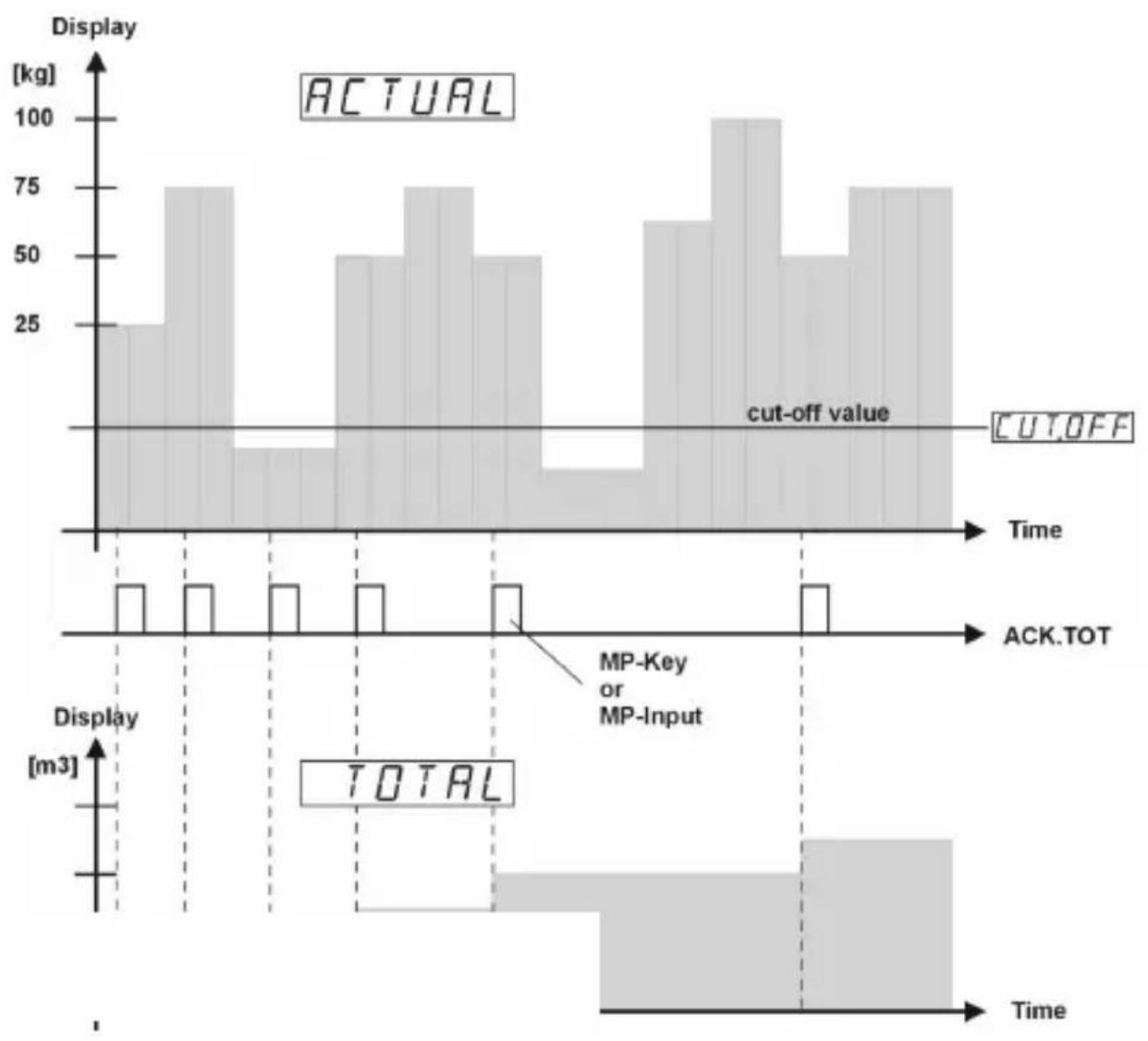
Using ACK.TOT the current (instantaneous) measured value (throughput rate) will be added into the totaliser memory. To convert the throughput rate into other units FACTOR and SCALE are available.
Negative measured values are also taken into consideration. A decimal point that is programmed with a current measured value is not taken into consideration. A dummy decimal point (optical indication only) can be programmed into the totaliser as required.
9.6 Limit Value (Alarm) Monitoring
| ALARM1 | Menu Alarm Output 1 |
| ALOUT1 | Select operating mode |
| OFF | OFF |
| AUTO | Automatic operation |
| LATCH | Memory latch operation - not with band limitation |
| ALLOC1 | Select source value for Alarm output 1 |
| ACTUAL | Current measured value |
| TOTAL | Totaliser |
| MOUT1 | Select Output triggering |
| INCR | With incrementing measuring signal |
| DECR | With decrementing measuring signal |
| BAN | Band limitation |
| FMOUT1 | Select Alarm status |
| -- | With alarm: output active |
| -- | With alarm: output inactive |
| ONHYS1 | Select on-hysteresis |
| 0.00 | Input range 0 ... +9999 and DP |
| OFHYS1 | Select off-hysteresis - only with auto operation |
| 0.00 | Input range 0 ... +9999 and DP |
| ONDLY1 | Select on-delay |
| 0.0 | Input range 0.0 ... 99.9 [sec] |
| OFDLY1 | Select off-delay - only with auto operation |
| 0.0 | Input range 0.0 ... 99.9 [sec] |
| ALARM2 | Menu Alarm Output 2 |
| ALOUT2 | Select operating mode |
| OFF | OFF |
| AUTO | Automatic operation |
| LATCH | Memory latch operation |
| ALLOC2 | Select source value for Alarm output 2 |
| ACTUAL | Current measured value |
| TOTAL | Totaliser |
| MOUT2 | Select Output triggering |
| INCR | With incrementing measuring signal |
| DECR | With decrementing measuring signal |
| BAN | Band limitation |
| FMOUT2 | Select Alarm status |
| - - - - - - - - - - - - - - - - - - - - - - - - - - - - - - - - - - - - - - - - - - - - - - - - - - - - - - - - - - - - - - - - - - - - - - - - - - - - - - - - - - - - - - - - - - - - - - - - - - - - - | |
| ONHY5.2 | Select on-hysteresis |
| 8.00 | Input range 0 ... +9999 and DP |
| OFHY5.2 | Select off-hysteresis - only with auto operation |
| 8.00 | Input range 0 ... +9999 and DP |
| ONDLY2 | Select on-delay |
| 8.0 | Input range 0.0 ... 99.9 [sec] |
| OFDLY2 | Select off-delay - only with auto operation |
| 8.0 | Input range 0.0 ... 99.9 [sec] |
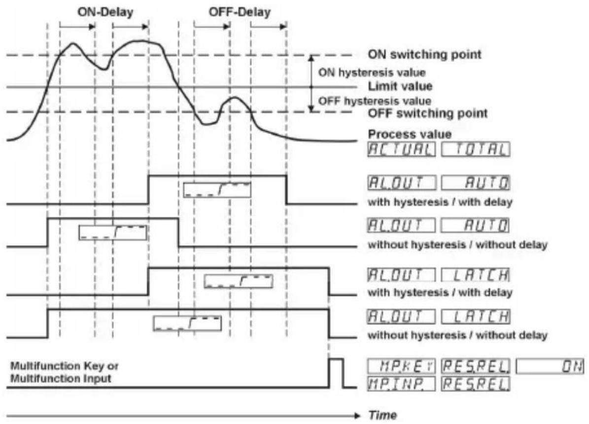
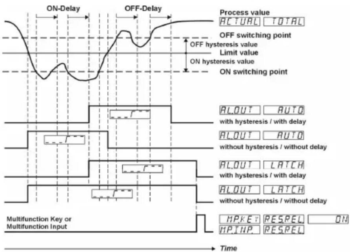
INCR ON switching point = limit value ^+ ON hysteresis OFF switching point = limit value-OFF hysteresis DECR ON switching point = limit value-ON hysteresis OFF switching point = limit value ^+ OFF hysteresis
An alarm is triggered, if the measured value falls outside a defined range (Band). Upper switching point = limit value ^+ ON hysteresis Lower switching point = limit value-OFF hysteresis
An alarm causes the output to become active (Relay energised, LED ON)
An alarm causes the output to become inactive (Relay not energised, LED OFF)
PHJELL LATCH In memory latch operation the status of the outputs is stored in the event of a Power OFF condition and then immediately restored at the next Power ON.
PHJELY AUTO In auto operation the status of the outputs is not saved in the event of a Power OFF condition. At the next Power ON the limit values are not processed until after the expiration of the start delay (PW.DELY).
Control with incrementing measuring signal
Control with decrementing measuring signal
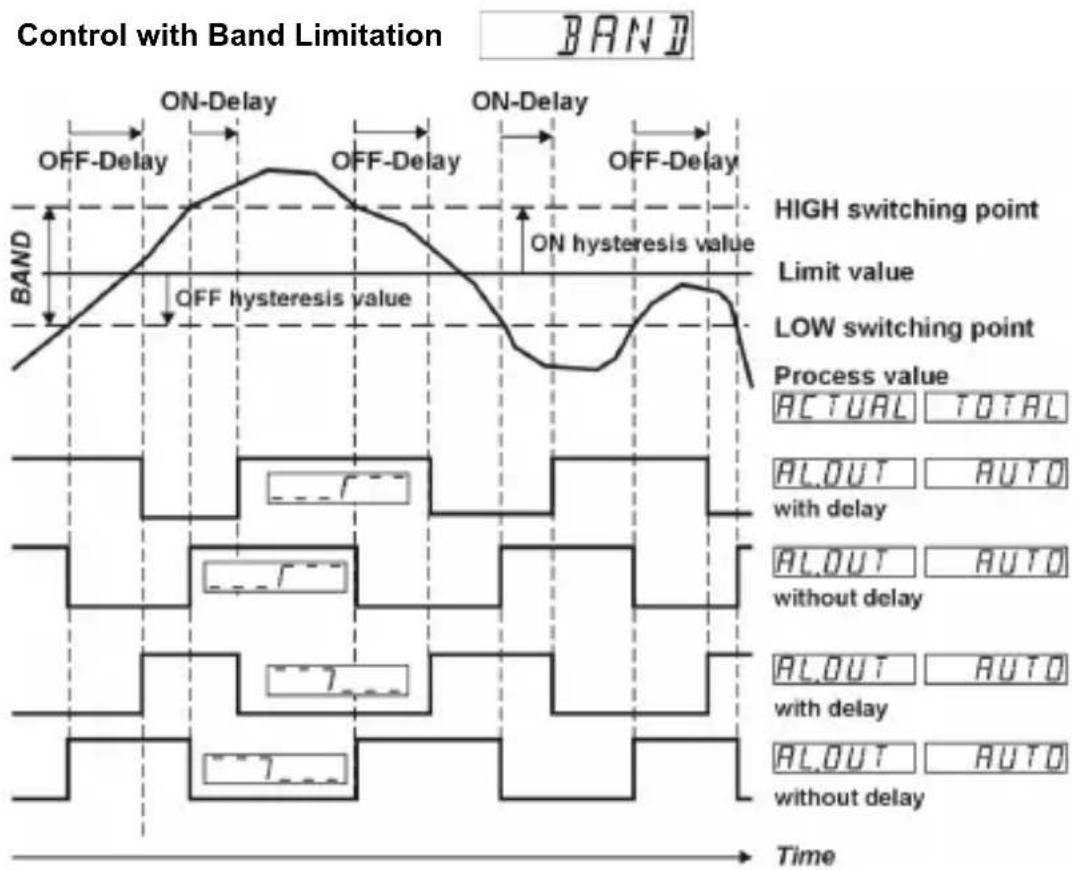
10 Monitoring of Measuring Circuit
| Meas. range | Lower Display Range limit DISPLC | Upper Display Range limit DISPHI | Lower Meas. Range limit LOLIM | Upper Meas. Range limit HILIM | Probe or wire short-circuit Probe or wire break 1) 2) |
| 3.3 mV/V | ■ ▲ □ □ | ■ | |||
| 3.0 mV/V | ■ ▲ □ □ | ■ | |||
| 2.0 mV/V | ■ ▲ □ □ | ■ | |||
| 1.5 mV/V | ■ ▲ □ □ | ■ | |||
| 1.0 mV/V | ■ ▲ □ □ | ■ | |||
| Indication | -19.99999 blinking | 9.999999 blinking blinking | UNDERFL blinking | OVERFL blinking | SENSOR blinking |
■=isdetected)
1) Wire short circuit between Signal input + and Signal input - is not detected.
2) Wire break with Sensor supply + or Sensor supply - is not detected.
11 Technical Data
11.1 General Data
Display: 6-digit, 14 segment LED
Digit height: 14 mm
Data retention: >10 years, EEPROM
Operation: 5 keys
11.2 Measuring signal inputs
Sampling rate: 10 readings/sec
Input resistance: 1 MΩ
Max. measuring
signal range: approx. ± 35 mV
Max. voltage ±10 V.
Strain gauge signal input
Sensitivity: 3.3mV / V;3.0mV / V
2.0 mV/V
Resolution: ± 15 Bit
Measuring accuracy typ. 0.05% of range
@ 23^ : max. ≤ 0.1% of range
Temperature drift: < 100~ppm / K
Sensitivity: 1.5mV / V;1.0mV / V
Resolution ± 14 Bit
Measuring accuracy typ. 0.1% of range
@ 23^ : max. ≤ 0.2% of range.
Temperature drift: < 100~ppm / K
11.3 Control Inputs MPI 1 / MPI 2
SELV circuits, reinforced / double insulation
Quantity: 2, optocouplers
Function: programmable
Switching levels: Low: < 2V
High: >4V (max. 30 V)
Pulse length: >100 ms
11.4 Alarm outputs
Relays: changeover contacts
Prescribed fuse: 5A
Switching voltage: max. 250 V AC / 125 V DC
min. 5 V AC / V DC
Switching current: max. 5 A AC/ A DC
min. 10mA
Switching capacity: max. 1250 VA / 150 W

The maximum values shall in no case be exceeded!
Mechanical service life (switching cycles) 1 × 10^7
N^ of switching cycles at 5A / 250VAC 5× 10^4
N^ of switching cycles at 5A / 30VDC 5× 10^4
1 1 . 5 Suppl y
AC supply: 100 ... 240 V AC / max. 9 VA
50/60 Hz, Tolerance ± 10%
ext. fuse protection: T 0.1 A
DC supply: 10 ... 30 V DC / max. 3.5 W
with galvanic isolation and,
reverse polarity protection
SELV,CLASS II (Limited
Power Source)
ext. fuse protection: T 0.4 A
Mains hum 50 Hz or 60 Hz,
suppression: programmable
11.6 Sensor supply voltage
for AC supply: 24 VDC ±15%, 30 mA
10 VDC ±1%, 30 mA
for DC-supply: 10 VDC ±1%, 30 mA
11.7 CImatictic
Operating temperature: -20^ ... +65^
Storage temperature: -25^ ... +75^
Relative humidity: R.H. 93% at +40^
non-condensing
Altitude: up to 2000 m
11.8 EMC
Noise immunity: EN61000-6-2
with shielded signal and
control cables
Noise emission: EN55011 Class B
1 1 . 9 D e v i c e Safety
Design to: EN 61010 Part 1
Protection Class: Protection Class 2 (front side)

Only the front side is classified as accessible for the operator.
Application area: Pollution level 2
over-voltage Category II
Insulation: Front: double insulation,
Rear side: basic insulation,
Signal inputs and und sensor power supply: SELV
11.10 Mechanical Data
Housing: Panel mount housing
to DIN 43700, RAL 7021
Dimensions: 96 × 48 × 102 ~mm
Panel cut-out: 92 +0.8 x 45 +0.6 mm
Installation depth: approx. 92 mm incl. terminals
Weight: approx. 180 g
Protection: IP 65 (front, device only)
Housing material: Polycarbonate UL94 V-2
Vibration resistance: 10 - 55Hz / 1mm /XYZ
EN60068-2-6 30 min in each direction
Shock resistance:
EN60068-2-27 100G/XYZ
3 times in each direction
EN60068-2-29 10G / 6 ms / XYZ
2000 times in each direction
11.11 Connections
Supply voltage and outputs:
Plug-in screw terminal, 8-pin, RM5.00
Core cross-section, max. 2.5mm
Signal and control inputs:
Plug-in screw terminal, 9-pin, RM 3.50
Core cross section, max. 1.5mm^2
12 Dimensional Drawings
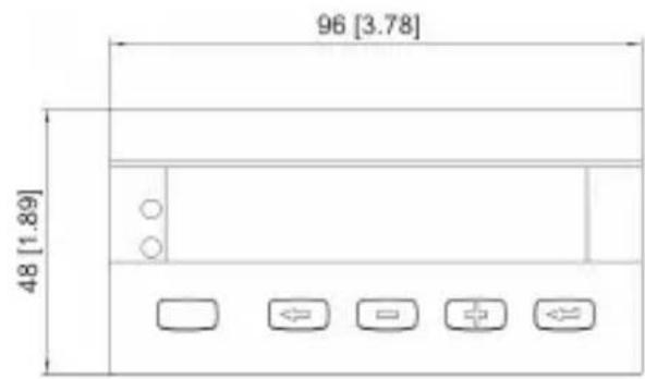
Dimensions in mm [inch]
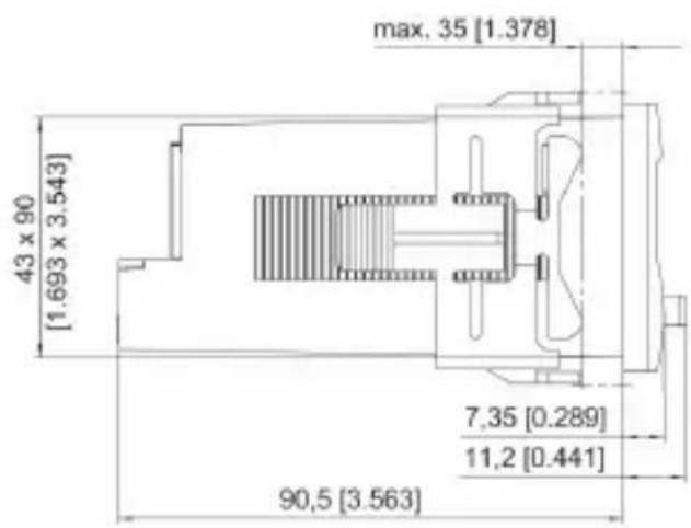
Panel cut-out: 92^+0,8 × 45^+0,6
13 Help Texts
| P R | O G | . N O PROGRAMMING |
| P R | O G | START PROGRAMMING S |
| HLP.TXT. | MAIN MENU SELECT HELPTEXT | |
| HLP.TXT. | ON | HELPTEXTS ON |
| H L P | . T X T O F F H E L P T E X T | |
| S L . | L A N G . D E S P R A C H E DEUTSCH | |
| S L . | L A N G . E N L A N G U A G E ENGLISH | |
| INPUT. MAIN MENU SIGNAL INPUT | ||
| RANGE 3.3MIV/V INPUT RANGE 3.3MV/V | ||
| RANGE 3.0MIV/V INPUT RANGE 3.0MV/V | ||
| RANGE 2.0MIV/V INPUT RANGE 2.0MV/V | ||
| RANGE 1.5MIV/V INPUT RANGE 1.5MV/V | ||
| RANGE 1.0MIV/V INPUT RANGE 1.0MV/V | ||
| LO.LIM. | LOWER INPUT RANGE LIMIT | |
| H I | . L | UPPERINPUT RANGE LIMIT |
| DP. | 0 | NO DECIMAL POINT |
| DP. | 0.0 | DECIMAL POINT 0.0 |
| D P | . | DECIMAL POINT 0.00 . 0 0 |
| D P | . | DECIMAL POINT 0.000 . 0 0 0 |
| D P | . | DECIMAL POINT 0.0000 . 0 0 0 0 |
| D P | . | DECIMAL POINT 0.00000 . 0 0 0 0 0 |
| INP.LO. | INPUT START VALUE | |
| DISP.LO. | DISPLAY START VALUE | |
| INP.HI. | INPUT END VALUE | |
| DISP.HI. | DISPLAY END VALUE | |
| FILTER | INPUT FILTER | |
| P W . D E L Y POWER-ON DELAY FOR OUTPUTS [SEC] | ||
| P W . F R E Q POWER OINB FREQUENCY 50HZ | ||
| P W . F R E Q POWER OINB FREQUENCY 60HZ | ||
| L I N E A MAIN MENU LINEARIZATION | ||
| L I N E A LINEARIZATION ON O | ||
| L I N E A LINEARIZATION ON E S | ||
| NUM.PNT. | NUMBER OF LINEARIZATION POINTS | |
| INP.01 | INPUT VALUE NO.1 | |
| DISP.01 DISPLAY VALUE NO.1 | ||
| to | ||
| INP.10 | INPUT VALUE NO.10 | |
| DISP.10 | DISPLAY VALUE NO.10 | |
| MP KEY | MAIN MENU MP-B BUTTON | |
| TARA | OFF | FUNCTION TAR A OFF |
| TARA | ON | FUNCTION TAR A ON |
| RES.MIN. | OFF | FUNCTION RESET MIN VALUE OFF |
| RES.MIN. | ON | FUNCTION RESET MIN VALUE ON |
| RES.MAX. | OFF | FUNCTION RESET MAX VALUE OFF |
| RES.MAX. | ON | FUNCTION RESET MAX VALUE ON |
| RES.REL. | OFF | FUNCTION RESET OUTPUT-LATCH OFF |
| RES.REL. | ON | FUNCTION RESET OUTPUT-LATCH ON |
| RES.TOT. | OFF | FUNCTION RESET TOTALIZER VALUE OFF |
| RES.TOT. | ON | FUNCTION RESET TOTALIZER VALUE ON |
| ACK.TOT. | OFF | FUNCTION ADD MEASURED VALUE TO TOTALIZER OFF |
| ACK.TOT. ON FUNCTION ADD MEASURED VALUE TO TOTALIZER ON | ||
| MP.INP. | MAIN MENU MP-INPUTS | |
| M P . | I N P | NO.FUNCTION N O . F U N C . |
| M P . | I N P | FUNCTION RESER MINVALSE . M I N . |
| M P . | I N P | FUNCTION RESER MAX VALSE . M A X . |
| M P . | I N P | FUNCTION RESER MIN/MAR VALUES A K S |
| M P . | I N P | FUNCTION RESER OUTPUT.SATCH R E L . |
| M P . | I N P | FUNCTION DISPLAY HOLD P . H D . |
| M P . | I N P | FUNCTION LOCKEDTING ALARM VALUESL R . |
| M P . | I N P | FUNCTION LOCKPROGRAMMING P R G . |
| M P . | I N P | FUNCTION LOCKKEYS C . K E Y |
| M P . | I N P . x T A R A F UN C T I O | |
| MP.INP.x R.TARA FUNCTION RESET TARALVALUE | ||
| MP.INP.x RES.TOT FUNCTION RESET TOTALIZER VALUE | ||
| M P . | I N P . x A C K . T O T F UN C | |
| T O | T A L M A I N MENU TO | |
| C U T . O F F C U T OFF VALUE | ||
| FACTOR MULTIPLICATION FACTOR TOTALIZER | ||
| SCALE x1 SCALING FACTOR TOTALIZER X1 | ||
| SCALE | x0.1 | SCALING FACTOR TOTALIZER X0.1 |
| SCALE | x0.01 | SCALING FACTOR TOTALIZER X0.01 |
| SCALE | x0.001 | SCALING FACTOR TOTALIZER X0.001 |
| SCALE x0.001 | SCALING FACTOR TOTALIZER X0.0001 | |
| DP.TOT. | 0 | NO DECIMAL POINT |
| DP.TOT. | 0.0 | DECIMAL POINT TOTALIZER 0.0 |
| DP.TOT. | 0.00 | DECIMAL POINT TOTALIZER 0.00 |
| DP.TOT. | 0.0000 | DECIMAL POINT TOTALIZER 0.0000 |
| DP.TOT | 0.00000 | DECIMAL POINT TOTALIZER 0.00000 |
| ALARMx | MAIN MENU ALARM x | |
| ALOUTx | OFF | ALARM x OFF |
| ALOUTx | AUTO | AUTOMATIC MODE OF ALARM OUTPUT x |
| ALOUTx | LATCH | LATCH MODE OF ALARM OUTPUT x |
| ALLOC.x | ACTUAL ACTUAL VALUE TO ALARM | |
| ALLOC.x | TOTAL | TOTALIZER TO ALARM |
| MD.OUTx | INCR | ALARM x ACTIVE AT INCREASING INPUT SIGNAL |
| MD.OUTx | DECR | ALARM x ACTIVE AT DECREASING INPUT SIGNAL |
| MD.OUTx | BAND | ALARM x BAND LIMITATION |
| FM.OUTx | =7= | OUTPUT ACTIVE AT ALARM |
| FM.OUTx | =7= | OUTPUT INACTIVE AT ALARM |
| ON.HYS.x | SWITCH ON HYSTERESIS ALARM x | |
| OF.HYS.x | SWITCH OFF HYSTERESIS ALARM x | |
| ON.DLY.x | ON DELAY ALARM x [SEC] | |
| OF.DLY.x | OFF DELAY ALARM x [SEC] | |
| END.PRG. | NO | REPEAT PROGRAMMING |
| END.PRG. | YES | EXIT PROGRAMMING AND STORE DATA |
| -1.9.9.9.9.9 | DISPLAYRANGE UNDERFLOW | |
| 9.9.9.9.9.9 | DISPLAYRANGE OVERFLOW | |
| OVERFL. | OVERFLOW UPPER INPUT RANGE LIMIT | |
| UNDERF. | UNDERFLOW LOWER INPUT RANGE LIMIT | |
| SENSOR | SENSOR ERROR | |
CODIX 566
SELV,CLASS II (Limited Power
Source)
Prof. de montage: env. 92 mm bornes comprises
Poids: env. 180 g
| ACK.TOT. ON | FUNCTION | ADD MEASURED VALUE TO TOTALIZER ON |
| MP.INP. | MAIN MENU MP-INPUTS | |
| M P . | I N P | NO.FUNCTION N O . F U N C . |
| M P . | I N P | FUNCTION RESET MINVALUE . M I N . |
| M P . | I N P | FUNCTION RESET MAX VALUE . M A X . |
| M P . | I N P | FUNCTION RESET MIN/MAR VALUE A K S |
| M P . | I N P | FUNCTION RESET OUTPUT&ATCH R E L . |
| M P . | I N P | FUNCTION DISPLAY HOLD S P . H D . |
| M P . | I N P | FUNCTION LOCKLEDITONG ACARM VALUESL R . |
| M P . | I N P | FUNCTION LOCKPROGRAMMING P R G . |
| M P . | I N P | FUNCTION LOCKKEYS C . K E Y |
| M P . | I N P | X T A R A F U N C T I O |
| MP.INP.x R.TARA FUNCTION RESET TARA VALUE | ||
| MP.INP.x RES.TOT FUNCTION RESET TOTALIZER VALUE | ||
| M P . | I N P | x A C K . T O T F U N Q |
| T O | T A | L M A I N MENU TO |
| C U T | . O F | F C U T OFF VALUE |
| FACTOR MULTIPLICATION FACTOR TOTALIZER | ||
| SCALE x1 SCALING FACTOR TOTALIZER X1 | ||
| SCALE | x0.1 | SCALING FACTOR TOTALIZER X0.1 |
| SCALE | x0.01 | SCALING FACTOR TOTALIZER X0.01 |
| SCALE | x0.001 | SCALING FACTOR TOTALIZER X0.001 |
| SCALE x0.001 | SCALING FACTOR TOTALIZER X0.0001 | |
| DP.TOT. | 0 | NO DECIMAL POINT |
| DP.TOT. | 0.0 | DECIMAL POINT TOTALIZER 0.0 |
| DP.TOT. | 0.00 | DECIMAL POINT TOTALIZER 0.00 |
| DP.TOT. | 0.000 | DECIMAL POINT TOTALIZER 0.000 |
| DP.TOT | 0.00000 | DECIMAL POINT TOTALIZER 0.00000 |
| ALARMx | MAIN MENU ALARM x | |
| AL_OUTx | OFF | ALARM x OFF |
| AL_OUTx | AUTO | AUTOMATIC MODE OF ALARM OUTPUT x |
| AL_OUTx | LATCH | LATCH MODE OF ALARM OUTPUT x |
| ALLOC.x | ACTUAL | ACTUAL VALUE TO ALARM |
| ALLOC.x | TOTAL | TOTALIZER TO ALARM |
| MD.OUTx | INCR | ALARM x ACTIVE AT INCREASING INPUT SIGNAL |
| MD.OUTx | DECR | ALARM x ACTIVE AT DECREASESING INPUT SIGNAL |
| MD.OUTx | BAND | ALARM x BAND LIMITATION |
| FM.OUTx | OUTPUT ACTIVE AT ALARM | |
| FM.OUTx | OUTPUT INACTIVE AT ALARM | |
| ON.HYS.x | SWITCH ON HYSTERESIS ALARM x | |
| OF.HYS.x | SWITCH OFF HYSTERESIS ALARM x | |
| ON.DLY.x | ON DELAY ALARM x [SEC] | |
| OF.DLY.x | OFF DELAY ALARM x [SEC] | |
| END.PRG. | NO | REPEAT PROGRAMMING |
| END.PRG. | YES | EXIT PROGRAMMING AND STORE DAT A |
| -1.9.9.9.9.9 | DISPLAYRANGE UNDERFLOW | |
| 9.9.9.9.9.9. | DISPLAYRANGE OVERFLOW | |
| OVERFL. | OVERFLOW UPPER INPUT RANGE LIMIT | |
| UNDERF. | UNDERFLOW LOWER INPUT RANGE LIMIT | |
| SENSOR | SENSOR ERROR | |
N
T
CODIX 566
50/60 Hz, Tolleranza ± 10%
5 T a SELV, QLASS II (Limited
Power Source)
| M P . | I N P FUNCTION RESER MAX VALUE . M A X . |
| M P . | I N P FUNCTION RESER MIN/MAX VALUE A K S |
| M P . | I N P FUNCTION RESER OUTPUT-SATCH R E L . |
| M P . | I N P FUNCTION DISPLAY HOLD S P . H D . |
| M P . | I N P FUNCTION LOCKEDTONG ACARM VALUESL R . |
| M P . | I N P FUNCTION LOCKPROGRAMMING P R G . |
| M P . | I N P FUNCTION LOCKKEYS C . K E Y |
| M P . | I AN PF . x U AT NA RC T I O N |
| M P . | I AN FUNCRION RESET TARA VALUET A R |
| MP.INP.x RES.TOT FUNCTION RESET TOTALIZER VALUE | |
| MP.INP.x | AC K . T ADD MEASURED VALUE TO TOTALIZER T I O N |
| T O | T A L M A I N MENU TO |
| C U T | . O F F C U T OFF VALUE |
| FACTOR MULTIPLICATION FACTOR TOTALIZER | |
| SCALE x1 SCALING FACTOR TOTALIZER X1 | |
| SCALE x0.1 SCALING FACTOR TOTALIZER X0.1 | |
| SCALE x0.01 SCALING FACTOR TOTALIZER X0.01 | |
| SCALE x0.001 SCALING FACTOR TOTALIZER X0.001 | |
| SCALE x0.001 SCALING FACTOR TOTALIZER X0.0001 | |
| DP.TOT. | 0 NO DECIMAL POINT |
| DP.TOT. | 0.0 DECIMAL POINT TOTALIZER 0.0 |
| DP.TOT. | 0.00 DECIMAL POINT TOTALIZER 0.00 |
| DP.TOT. | 0.000 DECIMAL POINT TOTALIZER 0.0000 |
| DP.TOT 0.0000 DECIMAL POINT TOTALIZER 0.00000 | |
| ALARMx | |
| AL_OUTx | OFF ALARM x OFF |
| AL_OUTx | AUTO AUTOMATIC MODE OF ALARM OUTPUT x |
| AL_OUTx | LATCH LATCH MODE OF ALARM OUTPUT x |
| ALLOC.x | ACTUAL ACTUAL VALUE TO ALARM |
| ALLOC.x | TOTAL TOTAL ALTERNATOR TO ALARM |
| MD_OUTx | INCR ALARM x ACTIVE AT INCREASING INPUT SIGNAL |
| MD_OUTx | DECR ALARM x ACTIVE AT DECREASESING INPUT SIGNAL |
| MD_OUTx | BAND ALARM x BAND LIMITATION |
| FM_OUTx | |
| FM_OUTx | |
| ON.HYS.x | |
| OF.HYS.x | |
| ON.DLY.x | |
| OF.DLY.x | |
| END.PRG. | NO REPEAT PROGRAMMING |
| END.PRG. | YES EXIT PROGRAMMING AND STORE DAT A |
| -1.9.9.9.9.9 | |
| 9.9.9.9.9.9. | |
| OVERFL. | |
| UNDERF. | |
| SENSOR | |
CODIX 566
SELV,CLASS II (Limited
Power Source)
Fusible externo T 0,4 A
Supresión de
Zumbido de la red: 50Hz o 60Hz programable