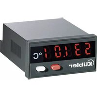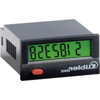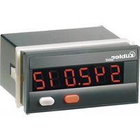
Codix 542 - Measuring equipment Kübler - Free user manual and instructions
Find the device manual for free Codix 542 Kübler in PDF.


User questions about Codix 542 Kübler
0 question about this device. Answer the ones you know or ask your own.
Ask a new question about this device
Download the instructions for your Measuring equipment in PDF format for free! Find your manual Codix 542 - Kübler and take your electronic device back in hand. On this page are published all the documents necessary for the use of your device. Codix 542 by Kübler.
USER MANUAL Codix 542 Kübler
4...30 V DC Pegel: Low: 0...2 V DC
High: 4...30 V DC
text_image
96 [3.78] 48 [1.89] max. 19 [0.748] 44.9 x 91.9 [1.768 x 3.619] 15.5 [0.61] 4 [0.158] 6.5 [0.256] 67.1 [2.642] 45-0.8 [1.772-0.024] 92-0.3 [3.622-0.032]Operating instructions Electronic display counter CODIX 541, 542, 543 and 544
1. Description
CODIX 541
Please note: Read first chapter 1-4 of CODIX 544 and go on on page 4.
CODIX 542
Please note: Read first chapter 1-4 of CODIX 544 and go on on page 6.
CODIX 543
Please note: Read first chapter 1-4 of CODIX 544 and go on on page 7.
CODIX 544
CODIX 544 is a multipurpose device. Depending on the programmed basic function, the device operates like
• the pulse counter CODIX 541 (see page 4) or
• the frequency meter CODIX 542 (see page 6) or
- the time meter CODIX 543 (see page 7)
1.1. Preface

Please read this instruction manual entirely and carefully before installation and start-up. Please observe all warnings and advice, both for your own safety and for general plant safety. If the device is not used in accordance with this instruction manual, then the intended protection can be impaired.
2. Safety Instructions and Warnings

Please use the device only if its technical condition is perfect. It should be used only for its intended purpose. Please bear in mind safety aspects and potential dangers and adhere to the operating instructions at all times.
Defective or damaged devices should be disconnected from the mains immediately and taken out of operation.
The device shall not be opened. Use the repair service of the manufacturer.
Only connect the device to the electricity networks provided to that purpose.
The safety of the system in which the device is integrated is the responsibility of the installer.
Disconnect all electricity networks prior to any installation or maintenance work.
Use exclusively cables approved in your country and designed for your temperature and power ranges.
Installation and service work shall be carried out exclusively by qualified personnel.
The device must compulsorily be protected with approved external fuses. The value of these fuses can be found in the technical information.

This symbol is used on the device to remind of the existence of dangers, which are referred to in this manual.
2.1 Use according to the intended purpose
The counter detects and measures pulses, times and frequencies up to max. 60 kHz and offers a wide variety of different operating modes. Use for any purpose over and beyond this will be deemed as not in accordance with its intended purpose and thus not complying with the requirements.
The application area for this device lies in industrial processes and controls, in the fields of manufacturing lines for the metal, wood, plastics, paper, glass, textile and other like industries. Over-voltages at the terminals of the device must be kept within the limits of over-voltage Category II.
The device must only be operated when mounted in a panel in the correct way and in accordance with the section "Technical Data".
The device is not suitable for use in hazardous areas and for areas excluded in EN 61010 Part 1. If the device is used to monitor machines or processes in which, in the event of a failure of the device or an error made by the operator, there might be the risk of damaging the machine or causing an accident to the operators, it is your responsibility to take the appropriate safety measures.
The device has been designed for indoor operation. It may nevertheless be used outdoors, provided the technical data is adhered to. In this case, take care to provide suitable UV protection.
2.2 Mounting in a control panel

CAUTION
Mount the device away from heat sources and avoid direct contact with corrosive liquids, hot steam or similar.
Provide a free space of 10 mm all around the device for its ventilation.
The device should be mounted so that the terminals are out of the reach of the operator and cannot be touched by him. When mounting the device, consider the fact that only the front side is classified as accessible for the operator.
Mounting instructions
- Remove the mounting clip from the device.
- Insert the device from the front into the panel cut-out, ensuring the front-panel gasket is correctly seated.
- Slide the fixing clip from the rear onto the housing, until the spring clamps are under tension and the upper and lower latching lugs have snapped into place.
Note: In case of proper installation, IP65 can be reached on the front side.
2.3 Electrical Installation

DANGER
The device must be disconnected from any power supply prior to any installation or maintenance work. Make sure that no more voltages LIABLE TO CAUSE AN ELECTROCUTION are present.
AC-powered devices must only be connected to the low-voltage network via a switch or circuit breaker installed close to the device and marked as their disconnecting device.
Installation or maintenance work must only be carried out by qualified personnel and in compliance with the applicable national and international standards.
Take care to separate all extra-low voltages entering or exiting the device from hazardous electrical conductors by means of a double or reinforced insulation (SELV circuits).

DANGER
The device must be protected externally for its proper operation. Information about the prescribed fuses can be found in the technical information.
It must also be made sure that, even in case of a malfunction, the values stated in the technical data are under no circumstances exceeded
- The cables and their insulation must be designed for the planned temperature and voltage ranges. Regarding the type of the cables, adhere to the applicable standards of the country and of the plant. The cross sections allowed for the screw terminals can be found in the technical data.
- Before starting the device, check the cables for proper wiring and tightening. The screws of unused screw terminals must be screwed to the stop, so that they cannot loosen and get lost.
- The device has been designed for overvoltage category II. If higher transient voltages cannot be excluded, additional protection measures must be taken in order to limit the overvoltage to the values of CAT II.
Advice on noise immunity
All connections are protected against external sources of interference. The installation location should be chosen so that inductive or capacitive interference does not affect the device or its connecting lines! Interference (e.g. from switch-mode power supplies, motors, clocked controllers or contactors) can be reduced by means of appropriate cable routing and wiring.
Measures to be taken:
- Use only shielded cable and control lines. Connect shield at both ends. The conductor cross-section of the cables should be a minimum of 0.14 mm^2 .
- The shield connection to the equipotential bonding should be as short as possible and with a contact area as large as possible (low-impedance).
- Only connect the shields to the control panel, if the latter is also earthed.
• Install the device as far away as possible from noise-containing cables. - Avoid routing signal or control cables parallel to power lines.
2.4 Cleaning and maintenance
The front side of the unit should only be cleaned using a soft damp (water!) cloth.
Cleaning of the embedded rear side is not planned and is the responsibility of the service personnel or of the installer. In normal operation, this device is maintenance-free. Should the device nevertheless not operate properly, it must be sent back to the manufacturer or to the supplier. Opening and repairing the device by the user is not allowed and can adversely affect the original protection level.
2.5 Start-up
The following points must be checked before starting up the device:
- Does the available supply voltage match the supply voltage of the device?
- Is the supply voltage connected to the good terminals of the device?
- For DC-powered devices, does the supply voltage respect the polarity?
- Is the device set and programmed correctly (function; for counters, max. counting frequency)?
2.6 Failure possibilities and causes
No display:
- No power supply
Keys cannot be operated:
• Key lock input is activated
Counter does not count:
- Wrong or reversed wiring of the counting input
- Setting of an input signal not matching the pulse generator
• Polarity (NPN/PNP) reversed - Gate input is active
- No ground connection between the pulse generator and the counter
• Maximum counting frequency exceeded - Signal levels do not reach the switching threshold of the counter
- Factor too small
Output signal is missing:
- Wrong output connection
- No ground connection to the following device
If, despite all, your device still does not operate, contact your local representative or call us directly for technical support.
When sending your device back, please attach a short description of the failure, of the programming and of the connection diagram, in order to allow us to reproduce a possibly existing defect and to repair your device as quickly as possible.
3. Setting of the operating parameters
a. Press both front side keys keys and switch on the supply voltage or, if the supply voltage is already on, press both keys simultaneously during 5 s.
b. The display shows
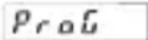
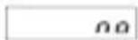
c. After releasing the keys, the display shows no
c1. Hold the left key pressed and press the right key to leave the programming operation.
c2. Press the right key to switch to
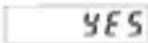
d. Hold the left key pressed and press the right key to switch to the first parameter.
e. After releasing the keys, the display alternates between the menu title and the current menu item setting. After pressing any key, only the menu item setting is displayed.
f. Pressing the right key, the menu item setting will be switched to the next value. If figures are to be input (e.g. when setting the scaling factor), select first the decade using the left key, and then set the value using the right key.
g. Hold the left key pressed and press the right key to switch to the next menu item.
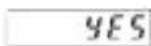
h. The last menu title "EndPro" allows, when selecting "Yes", to exit the programming menu and to take over (store) the new values. If "no" is selected, the programming routine is repeated, the latest values set remaining active. They can now be checked again or modified.
4. Programming routine
The first menu item is the selection of the basic operating mode, which determines the functions of the device.
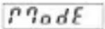
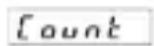
Operating mode pulse counter. Continued in point 4. of CODIX 541 on page 4.
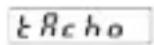
Operating mode frequency meter. Continued in point 4. of CODIX 542 on page 6.
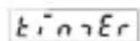
Operating mode time meter. Continued in point 4. of CODIX 543 on page 7.
Pulsecounter/Positionindicator CODIX 541
(CODIX 544: Operating mode pulse counter)
1. Description
- 6-digit display counter with SET/RESET-function
- Red LED display, character height 14 mm
• Display range from -199 999 to 999 999 - Leading zeros suppression
- Programming via two setting keys on the front side
- During programming, the display guides the user with text prompts
- Counter operating modes: Count input INP A + count direction input INP B (Cnt.Dir)
Differential count INP A - INP B (up.dn)
Totalising INP A + INP B (up.up)
Count Up/Down INP A 90° INP B x 1 (quAd)
Count Up/Down INP A 90° INP B x 2 (quAd2)
Count Up/Down INP A 90° INP B x 4 (quAd4)
- With AC power supply: sensor supply voltage 24 V DC ±15 %/100 mA
- Optional optocoupler output
2. Inputs
INP A
Dynamic count input.
INP B
Dynamic count input.
SET/RESET
Dynamic SET/RESET input. Linked in parallel to the red SET/RESET key. Resets the counter to the predefined setting value.
3. Optocoupler output (optional)
Active if count value < 0. Simple preset counter can be realized, when using subtract mode.
4. Programming routine
The programmable parameters of the device are described below, in the order in which they can be set. The device is fully programmed after one pass of the routine.
The first values stated correspond to the factory settings.
4.1 Polarity of the inputs
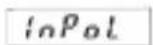

npn: switching for 0 V
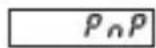
pnp: switching for +U_B
4.2 Switching on the 30 Hz filter (INP A, INP B)
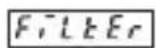
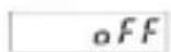
30 Hz filter off ( f_max )
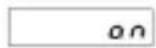
30 Hz filter on
4.3 Input mode
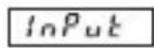
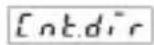
Count input and count direction input
INP A: Count input
INP B: Count direction input
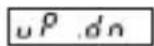
Differential input
IINP A: count input adding
INP B: count input subtracting

Totalising
INP A: count input adding
INP B: count input adding
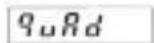
Quadrature input
INP A: count input 0°
INP B: count input 90°
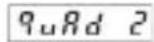
Quadrature input with pulse doubling
INP A: count input 0°
INP B: count input 90°
Each pulse edge of INP A will be counted
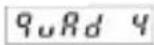
Quadrature input with pulse quadrupling
INP A: count input 0°
INP B: count input 90°
Each pulse edge of INP A and INP B will be counted.
4.4 Multiplying factor
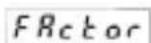
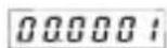
It can be set from 00.0001 up to 99.9999.
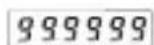
The decimal point is set to 4 decimal places. „0“ is not accepted!
4.5 Dividing factor
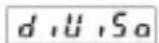
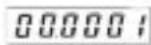
It can be set from 00.0001 up to 99.9999.
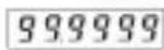
The decimal point is set to 4 decimal places. „0“ is not accepted!
4.6 Decimal point
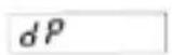
The decimal point defines the way of displaying the count values. It does not affect counting.
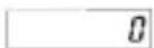
0 no decimal place
0.0 one decimal place
0.00 two decimal places
0.000 three decimal places
4.7 SET/RESET Mode
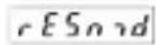
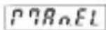
manual reset via the red SET/RESET key and electrical reset via the SET/RESET input
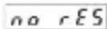
no reset (red SET/RESET key and SET/RESET input locked)
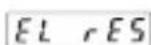
only electrical reset via the SET/RESET input
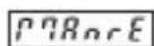
only manual reset via the red SET/RESET key
4.8 SET value
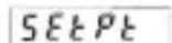
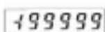
The device will be set to the set point by pressing the red SET/RESET key or activating the SET/RESET input. SET value -199 999...999 999 (number of decimal places depends on the decimal point option)
For programming the decimal point see 4.6
4.9 End of programming
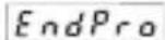
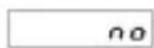
The programming routine is repeated once more. The values set until now can be checked and modified.

The programming routine will be left and all values set will be stored as new parameters.
Afterwards the device is ready for operation.
Tachometer/Frequency meter
CODIX 542 (CODIX 544: Operating mode frequency meter)
1. Description
• 6 digit frequency meter
• Red LED display, character height 14 mm
• Display range from 0 to 999 999
- Leading zeros suppression
- Programming via two setting keys on the front side
- During programming, the display guides the user with text prompts
• Value conversion and display in 1/s or 1/min
- With AC power supply: sensor supply voltage 24 V DC ±15 %/100 mA
- Optional optocoupler output
2. Inputs
INP A
Dynamic count input.
3. Optocoupler output (optional)
Active at f=0. Can be used e.g. to activate a "No operation" lamp.
4. Programming routine
The programmable parameters of the device are described below, in the order in which they can be set. The device is fully programmed after one pass of the routine.
The first values stated correspond to the factory settings.
4.1 Polarity of the inputs
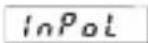
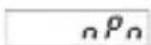
npn: switching for 0 V
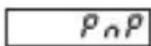
pnp: switching for +U_B
4.2 Switching on the 30 Hz filter
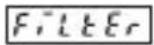
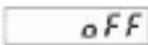
30 Hz filter off ( f_max )

30 Hz filter on
4.3 Multiplying factor
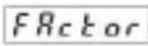
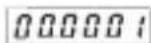
It can be set from 00.0001 up to 99.9999.
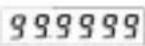
The decimal point is set to 4 decimal places.
„0“ is not accepted!
4.4 Dividing factor
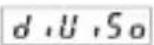
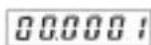
It can be set from 00.0001 up to 99.9999.
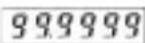
The decimal point is set to 4 decimal places. „0“ is not accepted!
4.5 Decimal point
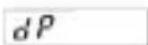
The decimal point defines the resolution
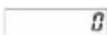
0 no decimal place
0.0 one decimal place
0.00 two decimal places
0.000 three decimal places
4.6 Display mode
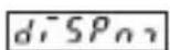
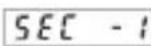
Value conversion and display in 1/s
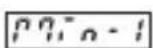
Value conversion and display in 1/min
4.7 Max. time to wait until „0“ is displayed
This parameter indicates, how long it takes, when measuring is active, until „0“ is displayed.
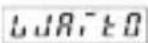
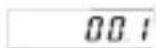
Max. time to wait 00.1 s (min. value)
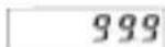
Max. time to wait 99.9 s
4.8 End of programming
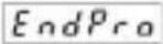
The programming routine is repeated once more. The values set until now can be checked and modified.
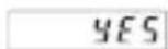
The programming routine will be left and all values set will be stored as new parameters.
Afterwards the device is ready for operation.
Time meter CODIX 543
(CODIX 544: Operating mode time meter)
1. Description
- 6 digit time meter with SET/RESET function
• Red LED display, character height 14 mm
• Display range from 0 to 999 999 - Leading zeros suppression
• Operation indicator: the decimal point of the lowest digit blinks while the count is active. - Programming via two setting keys on the front side
-
During programming, the display guides the user with text prompts
• Time meter operating modes -
Counting while INP B is inactive (GAtE.Lo)
- Counting while INP B is active (GatE.hi)
- Count Start/Stop with INP B edge (Inb.Inb)
-
Count Start with INP A edge, count Stop-with INP B edge (InA.Inb)
-
Counting ranges h; min; s; h.min.s
- With AC power supply: sensor supply voltage 24 V DC ±15 %/100 mA
- Optional optocoupler output
2. Inputs
INP A
Start input (depending on the input mode chosen)
INP B
Start/Stop or gate input (depending on the input mode chosen)
SET/RESET input
Dynamic SET/RESET input. Linked in parallel to the red RESET key. Resets the counter to the predefined setting value.
3. Optocoupler output (optional)
On active counting the output alternates at a frequency of 1 Hz between active and inactive.
4. Programming routine
The programmable parameters of the device are described below, in the order in which they can be set. The device is fully programmed after one pass of the routine.
The first values stated correspond to the factory settings.
4.1 Polarity of the inputs
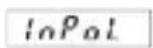
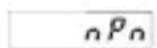
npn: switching for 0 V
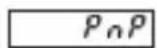
pnp: switching for +U_B
4.2 Switching on the 30 Hz filter (INP A, INP B)
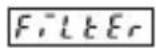
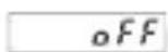
30 Hz filter off
Start/Stop inputs not damped

30 Hz filter on
Start/Stop inputs damped for use with me cha nical switches
4.3 Input mode

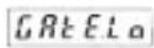
Start/Stop via Inp B. counting while Inp B (Gate) not active or open
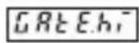
Start/Stop via Inp B. counting while Inp B (Gate) active (High level with pnp; Low level with npn)
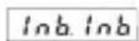
Count Start/Stop via INP B (LOW-HIGH edge with pnp; HIGH-LOW edge with npn). Every active edge changes the counter status.
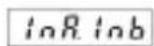
Count start via INP A, stop via INP B. (LOW-HIGH edge with pnp; HIGH-LOW edge with npn)
4.4 Operating mode
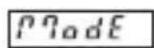
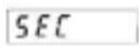
Time unit: seconds (accuracy depending on position of the decimal point*)
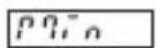
Time unit: minutes (accuracy depending on position of the decimal point*)
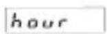
Time unit: hours (accuracy depending on position of the decimal point*)
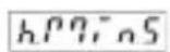
Time units: Hours:Minutes:Seconds (decimal point setting is ignored)
4.5 Decimal point
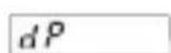
The decimal point defines the resolution of the pro gram med time unit.
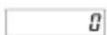
0 1
0.0 1/10 (0.1)
0.00 1/100 (0.01)
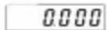
0.000 1/1000 (0.001)
4.6 SET/RESET mode
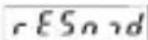
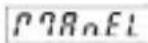
manual reset via the red SET/RESET key and electrical reset via the SET/RESET input
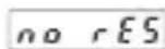
no reset (red SET/RESET key and SET/RESET input locked)
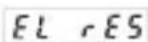
only electrical reset via the SET/RESET input
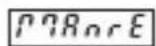
only manual reset via the red SET/RESET key
4.7 SET value
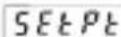
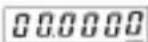
The device will be set to the set point by pressing the red SET/RESET key or activating the SET/RESET input.
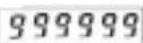
SET value 0...999 999 or 99.59.59 (number of decimal places depends on the decimal point option)
4.8 End of programming
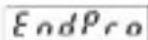

The programming routine is repeated once more. The values set until now can be checked and modified.
The programming routine will be left and all values set will be stored as new parameters.
Afterwards the device is ready for operation.
*0, 0.1, 0.01, 0.001 means: time measurement in 0, 0.1, 0.01, 0.001 time units
5. Technical data
Supply voltage
AC power supply: 100...240 VAC/max. 6 VA Tolerance ±10%, 50/60 Hz
ext. fuse protection: T 0.1 A
DC power supply: 10...30 V DC/max. 50 mA withinverse-polarity
SELV, CLASS II
protection
(Limited Power Source)
ext. fuse protection: T 0.1 A
Display: 6 digits, red 7 segment
LED display, height 14 mm
Data retention: EEPROM
Polarity of the inputs:
Programmable, npn or pnp
Input resistance: appr. 5 kOhm
Count frequency CODIX 541:
| AC power supply: | 100...240 VAC ±10% | |
| Input level: Standard | 4...30 V DC | |
| typ. Low Level: 2.5 V | 1.0 V | |
| typ. High Level: | 22.0 V | 4.0 V |
| Fmax: | kHz | kHz |
| CntDir | 60 | 50 |
| UpDown | 25 | 25 |
| Up.Up | 25 | 25 |
| Quad1 | 25 | 25 |
| Quad2 | 25 | 25 |
| Quad4 | 15 | 15 |
| DC power supply: | 24 | 12 V DC | 10...30 V DC |
| Input level: | Standard 4.. | .30 V DC | |
| typ. Low Level: | 2.5 | 2.0 V | 1.0 V |
| typ. High Level: | 22.0 | 10 V | 4.0 V |
| Fmax: kHz kHz | kHz | ||
| CntDir | 60 | 20 | 8 |
| UpDown | 25 | 15 | 8 |
| Up.Up | 25 | 15 | 8 |
| Quad1 25 15 | 8 | ||
| Quad2 25 15 | 8 | ||
| Quad4 15 15 | 8 | ||
Count frequency CODIX 542:
Frequency measurement
Accuracy <0.1 %
Measuring principle:
< 38 Hz: period measurement
38 Hz: gating time measurement gating time 26.3 ms
In case of frequencies < 10 Hz, the waiting time must be increased accordingly to obtain the display of a value.
| AC power supply: | 100...240 VAC ±10% | |
| Input level: Standard | 4...30 V DC | |
| typ. Low Level: 2.5 V | 1.0 V | |
| typ. High Level: 22.0 V | 4.0 V | |
| Fmax: kHz kHz | ||
| Tacho 60 60 | ||
| DC power supply: | 24 1 | 2 V DC 1 | 0...30 V DC |
| Input level: | Standard | 4...30 V DC | |
| typ. Low Level: | 2.5 | 2.0 V | 1.0 V |
| typ. High Level: | 22.0 | 10 V | 4.0 V |
| Fmax: | kHz | kHz kHz | |
| Tacho | 60 | 20 | 8 |
Counting ranges CODIX 543:
Seconds 0.001 s...999999 s
Minutes 0.001 min...999999 min
Hours 0.001 h...999999 h
h.min.s 00 h 00 min 01 s
... 99 h 59 min 59 s
Accuracy <50 ppm
Minimum pulse length for the Reset input:
5 ms
Input sensitivity:
SELV circuits, reinforced / double insulation
Standard sensitivity:
AC power supply Low: 0...4 V DC
High: 12...30 V DC
DC power supply Low: 0...0.2 x U_B [V DC]
High: 0.6 x U
B...30 V DC
4...30 V DC level: Low: 0...2 V DC
High: 4...30 V DC
Pulse shape: any,
Schmitt-Trigger inputs
Optocoupler output (optional):
NPN optocoupler with open collector and open
emitter; max. switching performance:
30 V DC/15 mA
Sensor supply voltage:
(Voltage output for external sensors)
SELV circuit, reinforced/double insulation
AC power supply 24 V DC ±15 %/100 mA
Ambient temperature:
-20 ...+65 °C
Storage temperature:
-25...+70 °C
Altitude: to 2000 m
EMC:
Noise emission: EN 55011 Class B
Noise immunity: EN 61000-6-2 with shielded signal and control cables
EN 61000-6-3
Device safety (for the AC models):
Design to: EN 61010 Part 1
Protection Class: Protection Class 2 (front side)

Only the front side is classified as accessible for the operator.
Application area: Pollution level 2 over-voltage Category II
Insulation:
Front: double insulation
Rear side: basic insulation
Signal inputs and
sensor power supply: SELV
Housing:
For front panel mounting: 96 x 48 mm acc. to DIN 43700, RAL7021, dark grey
Weight: appr. 150 g
Protection: IP65 (front, device only)
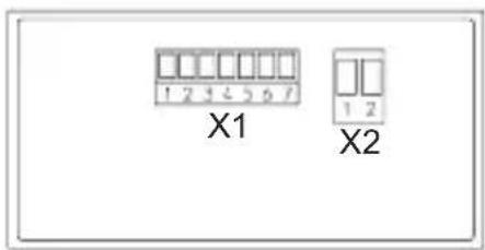
6. Terminal assignment
text_image
X1 X2X1 Terminal assignment
| Pin AC Version DC Version | |
| 1 Optocoupler output Collector | |
| 2 Optocoupler output Emitter | |
| 3 SET (n.c bei Codix 542) | |
| 4 INP B (n.c bei Codix 542) | |
| 5 INP A | |
| 6 GND n.c. | |
| 7 +24 Vout n.c. | |
X2 Terminal assignment
| Pin | AC Version DC Version |
| 1 | 100...240 VAC ±10% 0 V DC (GND) |
| 2 | 100...240 VAC ±10% 10...30 V DC |
7. Delivery includes:
Digital display
2 pin screw terminal RM 5.08
7 pin screw terminal RM 3.81
Panel mounting clip
Seal
Multilingual operating instructions
8. Ordering code:
6.541.01X.XX0
6.542.01X.XX0
6.543.01X.XX0
6.544.01X.XX0
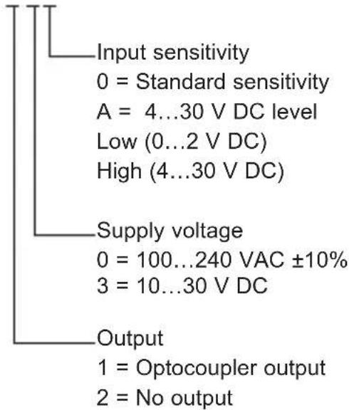
text_image
Input sensitivity 0 = Standard sensitivity A = 4...30 V DC level Low (0...2 V DC) High (4...30 V DC) Supply voltage 0 = 100...240 VAC ±10% 3 = 10...30 V DC Output 1 = Optocoupler output 2 = No output9. Dimensions:
Dimensions in mm [inch]
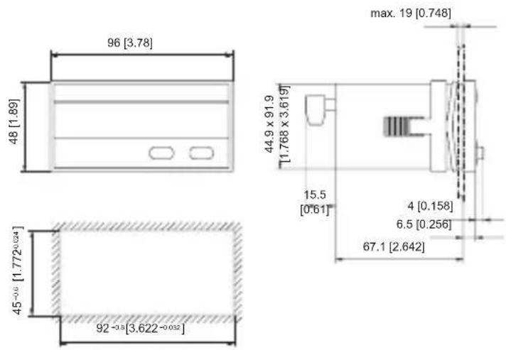
text_image
96 [3.78] 48 [1.89] max. 19 [0.748] 44.9 x 91.9 [1.768 x 3.619] 15.5 [0.61] 4 [0.158] 6.5 [0.256] 67.1 [2.642] 45 -0.6 [1.772^0.024] 92 -0.8 [3.622^-0.032]0 = 100...240 VAC ±10%
3 = 10...30 V DC
Sortie
text_image
96 [3.78] 48 [1.89]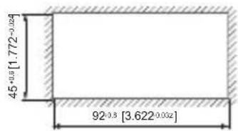
text_image
45⁺⁰·⁵ [1.772⁻⁰·⁰²] 92⁺⁰·⁵ [3.622⁻⁰·⁰³²]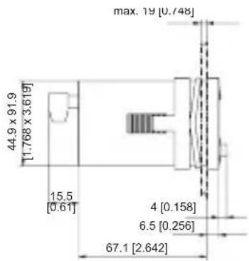
text_image
max. 19 [0.748] 44.9 x 91.9 [1.768 x 3.619] 15.5 [0.61] 4 [0.158] 6.5 [0.256] 67.1 [2.642]Tolleranza ±10%, 50/60 Hz
SELV, CLASS II (Limited
Power Source)
| Alimentazione AC: | 100...240 VAC ±10% | |
| Livello: Standard 4.. | 30 V DC | |
| typ. Low: 2,5 V 1,0 V | ||
| typ. High: 22,0 V 4,0 V | ||
| Fmax: kHz kHz | ||
| Tacho 60 60 | ||
| Alimentazione DC: | 24 | 12 V DC | 10...30 V DC |
| Livello: | Standard | 4...30 V DC | |
| typ. Low: | 2,5 | 2,0 V | 1,0 V |
| typ. High: | 22,0 | 10 V | 4,0 V |
| Fmax: | kHz | kHz | kHz |
| Tacho | 60 | 20 | 8 |
7. La consegna include:
Display digitale
text_image
96 [3.78] 48 [1.89] 45-0.8 [1.772+0.024] 92+0.3 [3.622+0.032] max. 19 [0.748] 44.9 x 91.9 [1.768 x 3.619] 15.5 [0.61] 4 [0.158] 6.5 [0.256] 67.1 [2.642](para los modelos AC):
text_image
96 [3.78] 48 [1.89] max. 19 [0.748] 44.9 x 91.9 [1.768 x 3.619] 15.5 [0.61] 4 [0.158] 6.5 [0.256] 67.1 [2.642] 45+0.6 [1.772+0.032] 92+0.8 [3.622+0.035]Kübler Group
Fritz Kübler GmbH
Schubertstrasse 47
D-78054 Villingen-Schwenningen
Germany
Phone: +49 7720 3903-0
Fax: +49 7720 21564
info@kuebler.com
www.kuebler.com