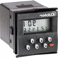
Typ 901 - Measuring equipment Kübler - Free user manual and instructions
Find the device manual for free Typ 901 Kübler in PDF.


| Product type | Preset counter (measuring equipment) |
| Dimensions (mm) | 60 x 75 x 69.2 (with terminal block) |
| Weight | Approx. 80 g |
| Power supply | 2 lithium batteries 1/2 AA 3.6 V |
| Display | LCD 2 lines of 6 decades (999999 max) |
| Main functions | Pulse and time counting, adding/subtracting modes, preset, programmable relay output |
| Max counting frequency | 30 Hz |
| Inputs | Counting, reset, key lock (12-250 V AC/DC or NPN) |
| Output | Dry contact relay, NO/NC, programmable, max 250 VAC/2A |
| Protection rating | IP65 (front panel) |
| Operating temperature | -20°C to +65°C |
| Relative humidity | <85% non-condensing |
| Material | Plastic housing |
| Mounting | Flush mount, cutout 45x45 mm or 50x50 mm depending on frame |
| Maintenance | Clean front panel with soft cloth, replace batteries |
| Safety | Disconnect all voltage before intervention, use external fuses, do not open except for batteries |
| Compliance | CE, UKCA, UL (file E128604) |
| Battery reference | N060045 Tadiran Lithium SL350/S |
| Data retention life | Min. 8 years at 25°C, 5x10⁶ switchings |
| Included accessories | 2 batteries, terminal block, front frames, mounting bracket, template, manual |
Frequently Asked Questions - Typ 901 Kübler
User questions about Typ 901 Kübler
0 question about this device. Answer the ones you know or ask your own.
Ask a new question about this device
Download the instructions for your Measuring equipment in PDF format for free! Find your manual Typ 901 - Kübler and take your electronic device back in hand. On this page are published all the documents necessary for the use of your device. Typ 901 by Kübler.
USER MANUAL Typ 901 Kübler
rELAY nc: Öffner (normally closed)
EMC Regulations S.I.: 2016/1091
Low Voltage Regulations S.I.: 2016/1101
RoHS Regulations S.I.: 2012/3032
UL Ratings: 2A, 30Vdc, 50°C
![max. 10.5 [2.413] 45 [1.772] 16 [0.65] 63.2 [2.409] 3 [1.116]](/content/2026/04/663774/images/5e913963934622e137c20fbe53c19847b655c38e8cff41e84d10f9c205e3b6d5.jpg)
Please read this instruction manual entirely and carefully before installation and start-up. Please observe all warnings and advices, both for your own safety and for operating safety. The intended protection can be impaired If the device is not used in accordance with this instruction manual.
1.2 Safety instructions and warnings

Please use the device only if its technical condition is perfect. It should be used only for its intended purpose, in accordance with this instruction manual.
Defective or damaged devices should be disconnected from the mains immediately and taken out of operation.
Repair work may be performed only by the manufacturer's repairs service.
This device may be opened only for battery replacement. For this purpose, the device must be separated from all electric circuits and de-energized.
Only connect the device to the electricity networks provided to that purpose.
The safety of the system in which the device is integrated is the responsibility of the installer.
Disconnect all electricity networks prior to any installation or maintenance work.
Use exclusively cables approved in your country and designed for your temperature and power ranges.
Installation and service work shall be carried out exclusively by qualified
personnel.
The device must compulsorily be protected with approved external fuses. The value of these fuses can be found in the technical information.

This symbol is used on the device to remind of the existence of dangers, which are referred to in this manual.
1.3 Use according to the intended purpose
The preset counter 901 counts pulses and times up to max. 30 Hz and offers various operating modes. The present counter simultaneously processes a programmed preset value. Any other use is considered as non compliant with the intended use.
The application area for this device lies in industrial processes and controls, in the fields of manufacturing lines for metal, wood, plastics, paper, glass, textile and other like industries. Overvoltages at the terminals of the device must be kept within the limits of Overvoltage Category II. The device must only be operated when properly mounted in a panel and in accordance with the section “Technical Data”.
The device is not suitable for use in areas with explosion protection and for areas excluded in EN 61010-1. If the device is used to monitor machines or processes in which, in the event of a failure of the device or an error made by the operator, there might be the risk of damaging the machine or causing an accident to the operators, it is your responsibility to take the appropriate safety measures.
The device has been designed for indoor operation. It may nevertheless be used outdoors, provided the technical data is complied with. In this case, take care to provide suitable UV protection.
1.4 Mounting in a control panel

CAUTION
Mount the device away from heat sources and avoid direct contact with corrosive liquids, hot steam or the like.
Provide a free space of 10 mm all around the device for its ventilation. The device should be mounted so that the terminals are out of the reach of the operator and cannot be touched by him. When mounting the device, consider the fact that only the front side is classified as accessible for the operator.
1.5 Mounting instructions
- Remove the mounting clip from the device.
- Insert the device from the front into the panel cut-out, ensuring the front-panel gasket is correctly seated.
- Slide the fixing clip from the rear onto the housing, until the spring clamps are under tension and the upper and lower latching lugs have snapped into place.
Note: In case of proper installation, IP65 can be reached on the front side.
1.6 Electrical installation
This device is powered by an internal battery.

DANGER
The device must be disconnected from any power supply prior to any installation or maintenance work. Make sure that no more voltages LIABLE TO CAUSE AN ELECTROCUTION are present.
Installation or maintenance work may only be carried out by qualified personnel and in compliance with the applicable national and international standards.
Take care to separate all extra-low voltages entering or exiting the device from hazardous electrical conductors by means of a double or reinforced insulation (SELV circuits).

DANGER
The device must be protected externally for proper operation. Information about the prescribed fuses can be found in the technical data.
The relay output is not protected / overcurrent-limited internally in the device. Without suitable protection of the relay output, undesired heat development or even fire may occur. The relay output must be protected externally by the manufacturer of the plant. It must also be made sure that, even in case of a malfunction, the values stated in the technical data are under no circumstances exceeded.
During installation, make sure that the voltage of the counting and reset inputs and the wiring of the output contacts are both powered by the same mains phase, in order not to exceed the maximum permitted voltage of 250V.
The cables and their insulation must be designed for the planned temperature and voltage ranges. Regarding the type of the cables, adhere to the applicable country and final device standards. The cross sections allowed for the screw terminals can be found in the technical data.
Before starting the device, check the cables for proper wiring and tightening. The screws of unused screw terminals must be screwed to the stop, so that they cannot loosen and get lost.
The device has been designed for overvoltage category II. If higher transient voltages cannot be excluded, additional protection measures must be taken in order to limit the overvoltage to the values of CAT II.
Advice on noise immunity
All connections are protected against external sources of interference. The installation location should be chosen so that inductive or capacitive interference does not affect the device or its connecting lines! Interference (e.g. from switch-mode power supplies, motors, clocked controllers or contactors) can be reduced by means of appropriate cable routing and wiring.
Measures
- Use only shielded cable for signal and control lines. Connect cable shield at both ends. Minimum cable conductor cross-section 0.14 mm2 .
- The shield connection to the equipotential bonding should be as short as possible and with a contact area as large as possible (low-impedance).
- Only connect the shields to the control panel, if the latter is also earthed.
• Install the device as far away as possible from noise-conducting cables. - Avoid routing signal or control cables parallel to power lines.
1.7 Cleaning and maintenance
The front side of the unit should only be cleaned using a soft damp (water!) cloth. Cleaning of the embedded rear side is not planned and is the responsibility of the service personnel or of the installer.
In normal operation, this device is maintenance-free. Should the device nevertheless not operate properly, it must be sent back to the manufacturer or to the supplier. Opening and repairing the device by the user is not allowed and can adversely affect the original protection level.
1.8 Start-up
- Is the device properly set and programmed (function; max. counting frequency for counters)?
1.9 Failure possibilities and causes
Impossible to use the keys:
• Key lock input activated
Counter does not count:
- Wrong or reversed wiring of the counting input
- Setting of an input signal not matching the pulse generator.
- No ground connection between the pulse generator and the counter.
- Signal levels do not reach the switching threshold of the counter.
Relay output signal missing:
• Output contact short-circuited
- Output signal (fugitive signal duration) programmed too short
- Relay contact defective due to excessive load
- Relay current below min. value
Displaying noFunc:
- Battery is unloaded and must be replaced.
If, despite all, your device still does not operate, contact your local representative or call us directly for technical support.
When sending your device back, please attach a short description of the failure, of the programming and of the connection diagram, in order to allow us to reproduce a possibly existing defect and to repair your device as quickly as possible.
2. Inputs
2.1 Reset input terminal 6
This input is connected functionally in parallel with the red Set key and sets the counter to zero in case of adding counting and to the pre-set value in case of subtracting counting. The reset function is dynamic.
2.2 Counting input (Start input) terminal 5 Input damped to 25 Hz for pulse counting with the pulse preset counter or static start input with the time preset counter (time counting active when input is active, time indicator located on top left flashes when time counting is active).
Note: The reset input (terminal 6) and the counting input (terminal 5) are inputs with a common connection (terminal 7) and must be controlled with the same polarity.
2.3 Key lock input
Tre front keys (including the set key) are locked when this input (terminal 2) is set to +3 VDC (terminal 1).
3. Output
Relay with potential-free contact, contact programmable as normally open or normally closed (terminal 3 and terminal 4). For the adding count, the relay is activated when > preset value, for the subtracting count, it is activated when < 0. The output signal is programmable as a fugitive signal between 0.1 and 99.9 seconds or as a bistable signal with the setting 0.0 (Loop OFF) no automatic repetition. When the relay is active, a colon symbol is displayed on the left end of the lower row. The output relay shall not exceed a switching frequency of 4 Hz.
4. Setting the operating mode and the operating parameters
4.1 New installation
In case of a new installation of the counter, after a battery replacement that lasted more than 20 seconds, or if the counter switched over to the „NoFunc“ safety mode because of a too low battery voltage, the preset counter switches automatically to the programming mode. All parameters must then be input again (see 4.2). Parameter modification is also possible during operation. For safety reasons, to access the programming mode, the reset key and the keys of the 5th and 6th decades must be pressed simultaneously. The lower display line then displays the message INIT. If these 3 keys remain pressed, a countdown from 5 to 0 takes place in one-second intervals. If the keys are released
during this countdown, the device switches back to the previous operating mode. If the keys are released after 0 is reached, parameter setting is activated and the first parameter is displayed.
4.2 Setting the parameters
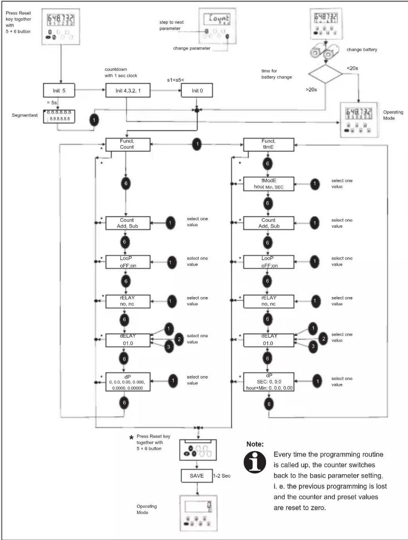
The key of the 1st decade allows switching among the available parameters (e.g. add-sub) and the key of the 6th decade allows switching over to the following function. The duration of the fugitive pulse is set using the keys of decades 1-3. After the last input (dP), the key of the 6th decade allows jumping back to the start of the programming routine; pressing simultaneously the reset key and the keys of the 5th and 6th decades allows saving the parameters.

Note: Every time the programming routine is called up, the counter switches back to the basic parameter setting, i. e. the previous programming is lost and the counter and preset values are reset to zero.
4.3 Parameters description
(see also the function sequence)
Funct.Count: Pulse preset counter operating mode
Funct.Time: Time preset counter operating mode
tMode: Programmable time range (only for Funct.Time), SEC=seconds, Min=minutes, hour=hours
Count Add: Adding counting mode
Count Sub: Subtracting counting mode
LooP off: Automatic repetition off
When parameter LooP is „c
dELAY time is 0.0, the output is activated when the preset value is reached and remains activated until reset is performed.
LooP on: Automatic repetition on
When parameter „LooP is „on“, the counter is reset automatically and the output emits a fugitive pulse for the time of the duration set in dELAY.
rELAY no: Normally open contact
rELAY nc: Normally closed contact
dELAY: Output signal duration: fugitive
signal programmable from 0.01 – 99.9 seconds, 0.0 = bistable output (active until reset) programmable only for Loop off, in case of Loop on, 0.0 is set automatically to 1.0 second.
dP: Programmable decimal point:
pulse preset counter: 0 - 0.00000 only for display purposes, time preset counter 0 - 0.0 (seconds) 0 - 0.00 (minutes, hours) determines the resolution.

If the relay output is switched from „no“ to „nc“, the relay condition must be taken over by pressing the reset key.
5. Operating the counter
5.1 Setting or resetting
The red set key or a pulse on the reset input sets the counter to zero in adding mode and to the preset value in subtracting mode.
5.2 Preset setting
The preset value is displayed in the lower display line. Setting is carried out with the 6 preset keys, each assigned to a decade. The set or modified preset value is taken over at the subsequent setting or resetting of the counter.
5.3 Overflow or underflow
In adding mode, overflow passes from 999999 to zero, in subtracting mode from zero to 999999. The output signal remains unchanged. The display flashes in case of overflow or underflow. The counter stops after the overflow or underflow of an additional decade.
5.4 Lo-Bat indicator
In case of a too low battery load, the message Lo-bat is displayed and the display flashes. The batteries must be replaced when „Lo-bat“ is displayed. If the battery voltage decreases in such a way that safe relay switching cannot be ensured any more, the counter switches to Safe Mode and displays the message „noFunc“. In this mode, the device does not count any more pulses or times, and the relay remains in its
last position. Thys way, the user knows exactly whether the plant is operating optimally, which allows preventing malfunctions. After battery replacement in „noFunc“ mode, the device requires re-parameterizing. Please read chapter Battery replacement to that purpose.

Note: In order to avoid loosing the settings and values because of switching to Safe Mode, the service plan of the device should include timely battery replacement in function of the ambient temperature and of the switching cycles of the relay.
5.5 Battery replacement
Before replacing the batteries, disconnect the voltages or switch the device off. Disconnect the connector from the device. This also makes sure that no untimely pulses set the device in an undefined state during battery replacement. Then push the battery lid backwards and remove the 2 batteries. Position the new batteries so that the „-“ pole is connected to the battery holder marked with „-“ on the printed circuit. After battery replacement, the display may go on displaying the LowBat message for 2 more minutes. Pressing the reset key can shorten this delay, as the device checks the current battery voltage every time this key is pressed. However, this also resets the current counter value.

Important: If battery replacement lasts longer than 20 seconds, the parameters, the preset value and the current counter value can be erased. In order to prevent this loss of information, we strongly recommend replacing the batteries one after the other.
Only use the batteries described in the Technical Data. Otherwise, proper operation cannot be guaranteed.
5.6 Segments test
Segments test is activated by pressing simultaneously the reset key and the keys of the 5th and 6th decades. Init 5 is then displayed; release immediately the keys, the segment test is started and all display segments are displayed. Pressing the 1st decade key calls up the programming mode; all parameters must then be re-programmed.
6. Terminal assignment
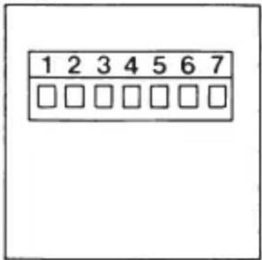
Device type:
x.901.xxx.850
NPN
![graph TD A["Key lock"] --> B["1"] A --> C["2"] A --> D["3"] A --> E["4"] A --> F["5"] A --> G["6"] A --> H["7"] I["Count/Start"] --> J["Resistor"] K["Reset"] --> L["Resistor"] M["Input"] --> N["Gate"] O["Output"] --> P["Gate"]](/content/2026/04/663774/images/408062a6a141469ba3a012b29ab144e1b9a07b8b3458c3fe1666d50b7766b56a.jpg)
8. Factory programming:
Function(Funct): counter(Count)
Counting mode(Count): adding(add)
Auto. repetition(LooP): none(oFF)
Output contact(rELAY): normally open
Output signal duration(dELAY): bistable output(0.0)
Decimal point(dP): none(0)
9. Interference suppression measures
The following interference suppression measures may be required: if the output switches inductive loads (relays, solenid valves), interferences must be suppressed by means of a freewheeling diode for direct current and of an RC element for alternating current. For safe and EMC-compliant operation, use shielded cables for the control inputs (counting, reset and key lock inputs). The shield must be connected at both ends. If this is not possible, a capacitor (e.g. 10 nf) may be integrated on one side in the shield connection.
10. Technical data
10.1 General technical data
| Display: | 2-line LCD display, each with 6 decades 999999; height 7 resp. 4,5 mm |
| Operating temperature: | -20°C ... +65°C (not condensing) |
| Storage temperature: | -25°C ... +70°C |
| Relative humidity: | <85 % (non-condensing) |
| Altitude: | up to 2000 m |
10.2 Electrical data
| Voltage supply: | 2 replaceable lithium batteries type 1/2 AA Lithium 3.6 V |
| Data backup: | min. 8 years for 5 x 10⁶ output relay switching cycles and 25°C operating temperature |
EMC:
Interference resistance: with shielded signal and control cables
Protection Class: Protection Class 2 (front side)

Only the front side is classified as accessible for the operator.
Application area: Pollution level 2
Insulation
Front side: Double / reinforced insulation
Relay: Basic insulation
Approvals
UL compliant in accordance with File no. E128604
CE compliant in accordance with
EMC Directive: 2014/30/EU
Low Voltage Directive: 2014/35/EU
RoHS Directive: 2011/65/EU
UKCA compliant in accordance with
EMC Regulations S.I.: 2016/1091
Low Voltage Regulations S.I.: 2016/1101
RoHS Regulations S.I.: 2012/3032
10.3 Mechanical data
Protection level: IP65 (font side)
Weight: appr. 80 g
10.4 Inputs
Inputs: Reset, counting and key lock inputs
Input polarity
(for reset and counting/start inputs):
12 ... 250 V AC/DC: bidirectional optocoupler input
NPN: NPN input activated by transistor or contact
Key lock input: is switched to +3 V DC (terminal 1)
Min. input pulse duration:
Reset input: 50 ms
Key lock input: 15 ms
Input switching level:
12 ... 250 V AC/DC: LOW: < 1 V AC/DC HIGH: 12...250 V AC/DC
NPN: LOW: 0 ... 0,8 V DC HIGH: 2.5 ... 30 V DC
Input frequency
Pulse counter: max. 30 Hz
Time counter: Measuring pulses < 200 ms are not measured accurately
Accuracy: System error +/- 100 ms per measuring pulse
Time accuracy: 200 ppm
Input resistance: 110 kΩ
10.5 Outputs
Outputs: bistable relay with potential-free contact – programmable as normally open or normally closed
Max. switching voltage:250 V AC / 30 V DC
Max. switching current: 2 A
Max. switching capacity:
60 VA / 30 W
Mechanical service life:1x10 7
Electrical service life: 5x10 5 (1A 30Vdc)
Output response time: < 20 ms, max. 4 Hz
Insulation coordination: Basic insulation
UL ratings: 2A, 30Vdc, 50°C
10.6 Fuses / overcurrent limitations
Input signals: In case of a failure, the current must be limited to a safe value via the inputs. We recommend a 0.1A/T fuse.
Relay: The maximum switching current of 2A shall in no case be exceeded.
10.7 Connections
7 plug-in screw terminals, pitch 5.08, cable cross section max. 2.5 mm.
10.8 Insulation coordination
Connections among each other x.901.xxx.820: only the counting and reset inputs have double / reinforced insulation x.901.xxx.850: generally only basic insulation
10.9 Consumables
Battery: order code: N060045 Tadiran Lithium SL350/S 1/2 AA 3.6V 1.2Ah
- Programming menu
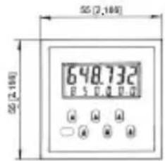
12. Dimensions
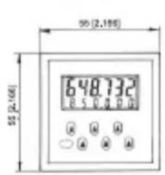
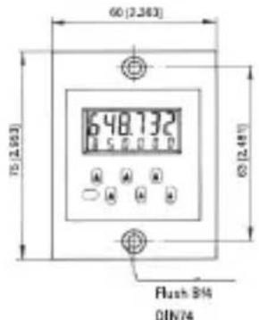
Dimensions in mm [inch]
Panel cut-out 45 x 45 [1.77 x 1.77]
![48 [1,00] 48 [1,00] 648.732 B S B C D A A A O A O A](/content/2026/04/663774/images/62ae5c8bf8f94bb630d4742cc59882ae5749f6e44cddf1f0bc47b1d62a0e148f.jpg)

With front bezel 55 x 55 [2.17 x 2.17], panel cut-out 50 x 50 [1.97 x 1.97]
![max.0,5 (2,376) 45 [1,772] 90 [1,800] 16 [0,83] 62.2 [2,445] 4 [0,198]](/content/2026/04/663774/images/977c87c41e73c2dbdd94d80df286ab8b1322fd55f76009a9d825b63d8867f612.jpg)
With front bezel 60 x 75 [2.36 x 2.95], panel cut-out 50 x 50 [1.97 x 1.97]
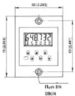
![max. 0,5 [0,374] 48 [5,772] 15 [0,89] 62,3 (2,449) 4 [0,150]](/content/2026/04/663774/images/ca63a6289adc3eeb0bb417fd8d00a57cd5324bf90b1fcfcfd8fd9f578c0ef33a.jpg)
13. Scope of the delivery
Counter 901
2 lithium batteries
1 plug-in screw terminal
1 front bezel for screw mounting, installation cross-section 50 x 50 mm
1 front bezel for clip mounting, installation cross-section 50 x 50 mm
1 mounting clip
1 template for front panel cut-out
1 operating instructions manual
14. Order code
6.901.x10.8y0
2 = 12 ... 250 V AC/DC inputs
5 = NPN inputs
0 = Kübler
A = Neutral
15. Battery ordinance
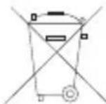
This device includes lithium batteries. In compliance with the Battery Ordinance, we want to point out the following:
Batteries shall not be disposed of in the residual waste; you are obliged by law to return them. You can send the complete devices back to us after use. If you can remove the batteries properly, you can also dispose of them at a municipal collection point or at a retailer collecting batteries.
Specific provisions on the return of lithium batteries:
Avoid short-circuits! Protect the poles of the battery with insulating adhesive tape. The poles of a lithium battery shall not come in contact with metal objects, neither by accident nor intentionally!
Pollutant-containing batteries bear a symbol made of a crossed-out bin and the chemical symbol of the heavy metal that determines their classification as containing pollutants. Thank you for your help!
1.1 Introduction

tMode: plage de temps programma- ble (Funct.Time uniquement), SEC=secondes, Min=minutes, hour=heures
Faceavant: Isolation
double / renforcée
Relais: Isolation de base
Homologations
Directive CEM: 2014/30/EU
Directive Basse Tension: 2014/35/EU
Directive RoHS: 2011/65/EU
Normative CEM S.I.: 2016/1091
Normative Bassa Tensione S.I.: 2016/1101
Normative RoHS S.I.: 2012/3032
![45 [1.772] 16 [0,60] 63.2 [2,689] 2 [0,116] max. 10.5 [2,18]](/content/2026/04/663774/images/5777bb24ef0fcf61a20d0481c0ebe2815b4b750e5ec25170a015fc55ba32545c.jpg)
Con quadro frontale 55 x 55 [2.17 x 2.17], apertura d'incastro 50 x 50 [1.97 x 1.97]

![max. 0,5 (3,274) 48 [1,772] 90 (1,668) 16 (3,83) 62,2 (2,443) 4 (2,158)](/content/2026/04/663774/images/7dca1b74a9381dde5f61cd7d43746e8e73f8d1d627a77472faca3457016bc45c.jpg)
Con quadro frontale 60 x 75 [2.36 x 2.95], apertura d'incastro 50 x 50 [1.97 x 1.97]
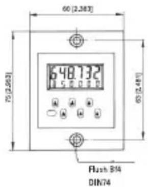
![max.9,5[0,374] 60(1,772) 18 [0,89] 62,2(2,448) 4[0,150]](/content/2026/04/663774/images/c00e61babc81a9a6f7f7e4f25d17c315a57f030a4ddc50ff24b499fbbd63f94e.jpg)
13. Fornitura:
Contatore 901
2 batterie al litio
1 morsetti a vite
UL Ratings: 2A, 30Vdc, 50°C
![45 (1.772) 16 [0.03] 63.2 (2.488) 3 (5.116) max. 10,5 (9,618)](/content/2026/04/663774/images/ffec251967d211535849be6ca8ceeb8667ad2584e6c32975e436372bdf519a33.jpg)
Con marco frontal 55 x 55 [2.17 x 2.17].
recorte del cuadro de mando 50 x 50 [1.97 x 1.97]
![48(1.772) 16 [0,63] 62,2 (0,448) 4 (0,158) 93 (1,000)](/content/2026/04/663774/images/b5dca972ffebcae362afabee1beec5cff4df10e168c4f21e17b969f0f4ce9713.jpg)
Con marco frontal 60 x 75 [2.36 x 2.95].
recorte del cuadro de mando 50 x 50 [1.97 x 1.97]
![max. 9,5 [0,374] ∅2 (1,772) 18 [0,23] 60,2 (2,448) 4 (0,150)](/content/2026/04/663774/images/6323247a8a060ecc5c6e8a7b983f466c71c50d00b2009dff6b5d98f6516ee139.jpg)
13. Se incluye:
Contador 901
2 baterías de litio
1 bornera roscada insertable
- 1.2 SAFETY INSTRUCTIONS AND WARNINGS
- 1.3 USE ACCORDING TO THE INTENDED PURPOSE
- 1.4 MOUNTING IN A CONTROL PANEL
- 1.5 MOUNTING INSTRUCTIONS
- 1.6 ELECTRICAL INSTALLATION
- ADVICE ON NOISE IMMUNITY
- MEASURES
- 1.7 CLEANING AND MAINTENANCE
- 1.8 START-UP
- 1.9 FAILURE POSSIBILITIES AND CAUSES
- INPUTS
- 2.1 RESET INPUT TERMINAL 6
- 2.3 KEY LOCK INPUT
- OUTPUT
- SETTING THE OPERATING MODE AND THE OPERATING PARAMETERS
- 4.1 NEW INSTALLATION
- 4.2 SETTING THE PARAMETERS
- 4.3 PARAMETERS DESCRIPTION
- (SEE ALSO THE FUNCTION SEQUENCE)
- OPERATING THE COUNTER
- 5.1 SETTING OR RESETTING
- 5.2 PRESET SETTING
- 5.3 OVERFLOW OR UNDERFLOW
- 5.4 LO-BAT INDICATOR
- 5.5 BATTERY REPLACEMENT
- 5.6 SEGMENTS TEST
- TERMINAL ASSIGNMENT
- FACTORY PROGRAMMING
- INTERFERENCE SUPPRESSION MEASURES
- TECHNICAL DATA
- 10.3 MECHANICAL DATA
- 10.4 INPUTS
- 10.5 OUTPUTS
- 10.6 FUSES / OVERCURRENT LIMITATIONS
- 10.7 CONNECTIONS
- 10.8 INSULATION COORDINATION
- 10.9 CONSUMABLES
- DIMENSIONS
- SCOPE OF THE DELIVERY
- ORDER CODE
- BATTERY ORDINANCE
- SPECIFIC PROVISIONS ON THE RETURN OF LITHIUM BATTERIES
- 1.1 INTRODUCTION
- FORNITURA
- SE INCLUYE
Brand : Kübler
Model : Typ 901
Category : Measuring equipment