61800 - Backpack sprayer Chapin - Free user manual and instructions
Find the device manual for free 61800 Chapin in PDF.

User questions about 61800 Chapin
0 question about this device. Answer the ones you know or ask your own.
Ask a new question about this device
Download the instructions for your Backpack sprayer in PDF format for free! Find your manual 61800 - Chapin and take your electronic device back in hand. On this page are published all the documents necessary for the use of your device. 61800 by Chapin.
USER MANUAL 61800 Chapin
Failure to do so may result in damage to property and/or person.
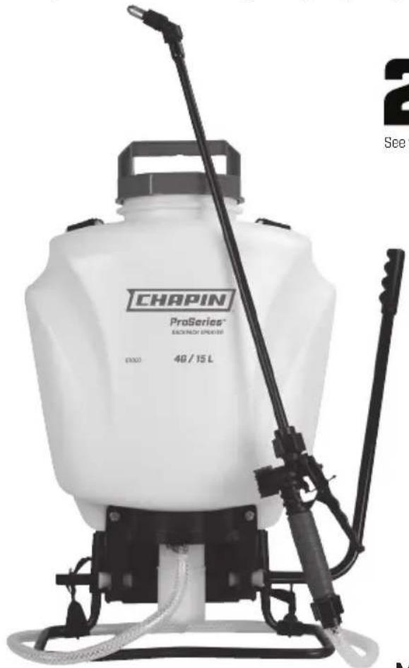
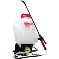
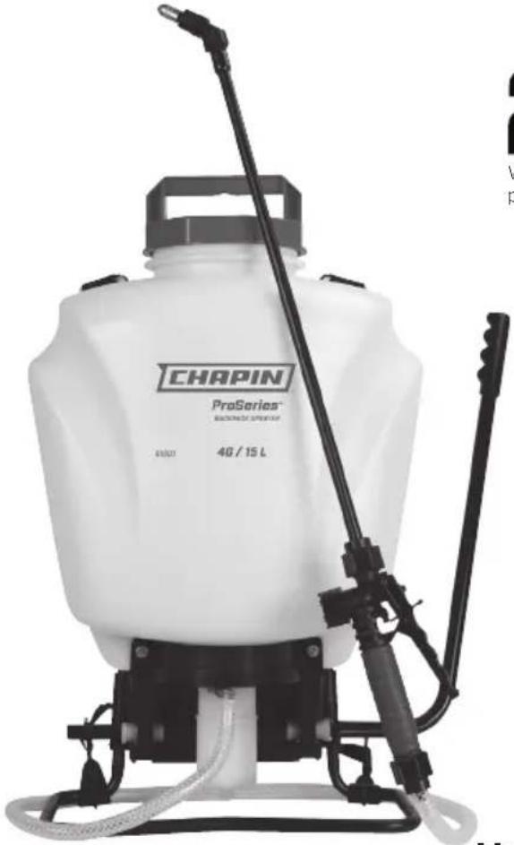
natural_image
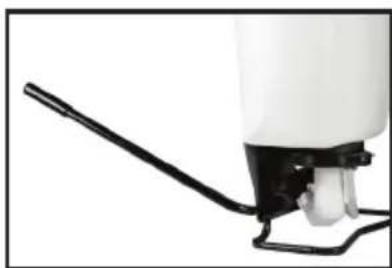
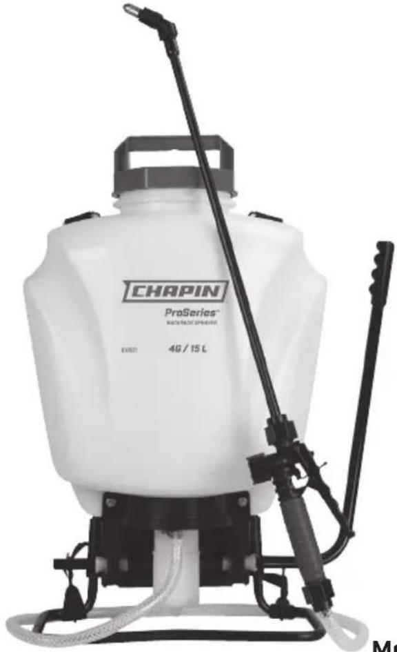
Exterior view of a modern agricultural sprayer with a black lever and spray bottle (no text or symbols visible on the device itself)
See website for warranty detail
Model 61800 · 4G/ 15L
CONGRATULATIONS!
YOU HAVE JUST PURCHASED A QUALITY CHAPIN PRODUCT.
REGISTER YOUR PRODUCT ONLINE @ WWW.CHAPINMFG.COM
VISIT US ON THE INTERNET: WWW.CHAPINMFG.COM
BEFORE RETURNING THIS PRODUCT FOR ANY REASON, PLEASE CALL:
1-800-950-4458
When calling, please have the following information available: Sales receipt & model number. This number connects you directly with the manufacturer of this product. Our Technical Support Team will be happy to help you with any assembly, troubleshooting and replacement information you may need.
WARNING
WARNING: IMPROPER USE OR FAILURE TO FOLLOW INSTRUCTIONS CAN RESULT IN EXPLOSIVE FAILURE CAUSING SERIOUS EYE OR OTHER INJURY.
For safe use of this product you must read and follow all instructions. Do not leave a pressurized sprayer in the hot sun. Heat can cause pressure build-up resulting in possible explosion. Do not store or leave solution in tank after use. Always wear goggles, gloves, long sleeve shirt, long pants and full foot protection when spraying. Never use any tool to remove pump if there is pressure in the pressure chamber. Never pressurize sprayer by any means other than the original pump. Do not attempt to modify this sprayer. Replace parts only with manufacturer's original parts.
Never spray flammable, caustic, acidic, chlorine, bleach or other corrosive solutions or heat, pressure, or gas producing chemicals. Always read and follow chemical manufacturer's instructions before use with this sprayer as some chemicals may be hazardous when used with this sprayer.
SK 1158-1
CAUTION
- PRE-USE CHECK: Before each use check tightness of hose nut to be sure hose is securely attached to the shut-off assembly. Ensure hose is securely attached to the tank by tightening hose clamp if necessary. Ensure that all nozzle and wand connections are tight. Insure the large pump clamp is tight. Insure the 2 bolts used to attach the pump lever to the pump shaft are tight.
- Do Not exceed a tank solution temperature of 120^ / 49^ .
NOTE: The tank and hose may have residual water in it due to quality testing performed on the sprayer.
"Always review all instructions with respect to any liquid or other material before placing inside this product, and always abide by such instructions. Always label this product with the full name of any liquid or other material placed inside this product.
Always ensure all old liquid or other materials are removed from this product before placing any different liquid or other material in this product.
DISCLAIMER: The Manufacturer is not responsible for, and assumes no liability with respect to, any liquid or other material placed inside this product. All liquids and other materials placed inside this product, and the use of any such liquids and other materials with this product, are at your own risk."
APPLICATIONS & USE FOR YOUR SPRAYER
Avoid using a sprayer for general cleaning purposes if plant protection or herbicide chemicals have already been used in the sprayer. If a sprayer has been used for plant protection or as an herbicide, clean the sprayer completely (see cleaning section) before using.
Plant Food: Use different spray patterns for optimum foliage feeding or for fungicide and pesticide application.
Herbicides: Reduce weeds and unwanted plants but avoid using the same sprayer for plant feeding or protection without thoroughly cleaning (see cleaning section) the sprayer first.
General Household Use: Apply detergents, cleaning solutions, warm water (do not exceed 120^ F/49°C) or nontoxic household cleaning chemicals for carpets, floors, walls, glass, counter tops and ceilings. DO NOT use sprayer that has been used with herbicides, pesticides or other toxic chemicals for household applications.
General Outdoor Use: Use the sprayer for cleaning windows or with a detergent for general purpose cleaning.
SPRAYER COMPONENTS & USE INFORMATION
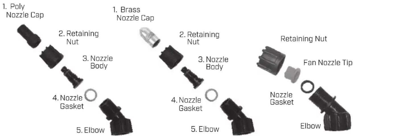
NOZZLE ASSEMBLY
Figure 1-2
Unscrew the nozzle cap (1) from the nozzle body (3) with retaining nut (2) fastened tightly to the elbow (5). Unscrew the retaining nut (2). Push the nozzle body (3) with the nozzle gasket (4) out of the retaining nut (2). To reinstall the nozzle, reverse the above instructions.
Figure 3
Unscrew the retaining nut from the elbow and push the fan nozzle tip and gasket out of the retaining nut. To reinstall the nozzle, reverse the above instructions.
text_image
1. Poly Nozzle Cap 2. Retaining Nut 3. Nozzle Body 4. Nozzle Gasket 5. Elbow 1. Brass Nozzle Cap 2. Retaining Nut 3. Nozzle Body 4. Nozzle Gasket 5. Elbow Retaining Nut Fan Nozzle Tip Nozzle Gasket ElbowFigure 3 Figure 2 Fi
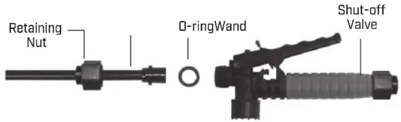
WAND ASSEMBLY
- Make sure the o-ring is installed on the end of the wand. Insert the wand into shut-off valve.
- Turn and tighten the retaining nut clock-wise onto the shut-off valve.
text_image
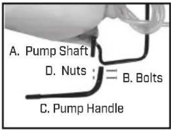
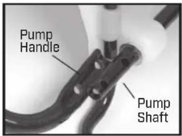
Retaining Nut O-ringWand Shut-off ValveINSTALLING THE PUMP HANDLE
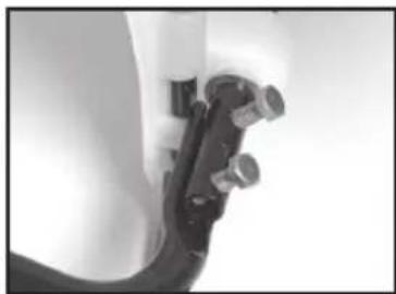
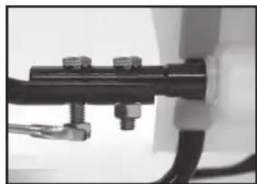
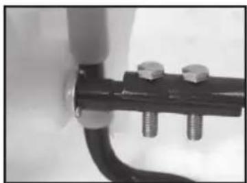
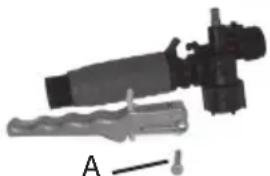
The pump handle can be mounted on either side of the pump shaft [A]. To install the pump handle place the handle [C] over the shaft [A] aligning the pump handle holes and shaft holes. Slide the bolts [B] through the aligned holes as shown in figure 3. Tighten nuts [D] to bolts. There are holes in the pump handle to allow for either left (fig.2-4) or right (fig.5) hand mounting.
text_image
A. Pump Shaft D. Nuts : = B. Bolts C. Pump Handle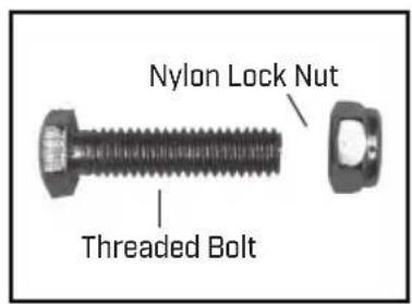
text_image
Nylon Lock Nut Threaded BoltFigure 1 Figure 2
text_image
Pump Handle Pump ShaftLine up holes
natural_image
Close-up of a mechanical component with bolts and a curved handle (no visible text or symbols)Figure 3 Slide bolts through holes
natural_image
Close-up of a mechanical assembly with bolts and wires (no visible text or symbols)Figure 4 Tighten nut to bolt
natural_image
Close-up of a mechanical pipe fitting with two bolts and a curved base (no text or symbols visible)Figure 5 Right Hand
natural_image
Close-up of a white spray can with a black handle and white spray bottle (no text or symbols visible)Completed Assembly
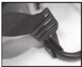
INSTALLING THE SHOULDER STRAP
The top of the shoulder straps are attached to the tank. Attach the lower end of the straps by clipping the strap hooks to the metal frame between where the frame exits the tank and curves around.
natural_image
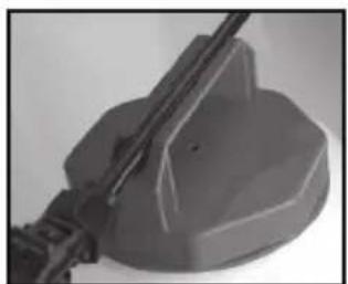
Close-up of a black plastic tool tip interacting with a curved wire (no visible text or symbols)WAND HOLDER
The wand easily snaps into handle.
natural_image
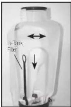
Close-up of a mechanical component with a cylindrical rod inserted into a stepped base (no visible text or symbols)3 STAGE FILTERING SYSTEM
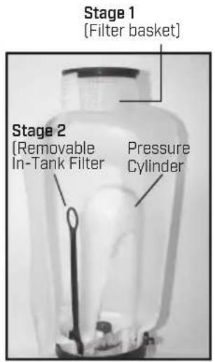
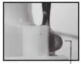
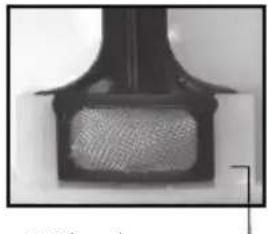
This backpack sprayer is equipped with a 3 stage filtering system (see figure 1). Stage 1 is a filter basket incorporated into the tank opening where fluid is added. Stage 2 filter is located at the inlet of the pressure cylinder. Stage 2 is a removable In-Tank filter. Stage 3 is a removable filter incorporated into the shut-off assembly. Periodic cleaning of these filters is recommended to insure consistent fluid flow through the sprayer. This will also reduce sprayer component wear.
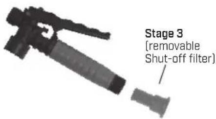
The stage 3 filter is a removable filter incorporated into the inlet side of the shut-off valve [see section "disassembling and repairing the shut-off valve"]. Make sure pressure is released before detaching the hose from the shut-off. It is best to have no or minimal fluid in the pressure cylinder before removing and reinstalling the stage 3 shut-off filter as fluid can leak from the hose.
text_image
Stage 1 [Filter basket] Stage 2 (Removable In-Tank Filter Pressure CylinderFigure 1
Figure 2 Stage 2 (removable In-tank filter)
natural_image
Close-up of a mechanical component with a curved surface and a circular feature (no visible text or symbols)Guide edge facing away from pressure cylinder
natural_image
Close-up of a black mechanical component with textured surface (no visible text or symbols)Guide edge on pressure cylinder
text_image
Stage 3 (removable Shut-off filter)FILLING THE SPRAYER
Make sure the filter basket is in place to keep debris from entering the tank.
Determine the amount of mixture needed for your application. Add the proper amount of water to the tank. Add the proper amount of chemical to the tank [check the chemical label for proper ratio of chemical]. Stir mixture in tank with a clean utensil (like a paint stirrer). The tank will hold the 4-gallon [15.1L] capacity plus the chemical.
It is not necessary to completely fill the sprayer tank with each use. You can fill the tank with only the amount needed for each application.
Always follow the manufacturer's instructions included on their product label.
HELPFUL SPRAYING INFORMATION
Use RAPID pump strokes to prime the pump. You will know the pressure chamber is filling with liquid when you feel firm resistance from the pump. The air in the pressure chamber is compressed from repeated strokes. By pressing the hand lever on the shut-off, the valve opens. For safety lock-off feature (no-spraying), pull up on handle and move red locking mechanism into lock-off position as shown in fig. 1. To disengage, pull up on handle and return red locking mechanism to neutral position as in fig. 3. For lock-on feature (continuous spraying), push down on handle and move red locking mechanism into lock-on position as shown in fig. 2. To disengage, push down on handle and return red locking mechanism to neutral position as shown in fig. 3.
LOCK-ON POSITION NEUTRAL POSITIONLOCK-OFF POSITION
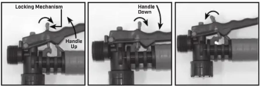
Figure 1 Figure 2 Figure 3
For easy pump action use the END of the pump handle. The amount of liquid delivered during spraying depends on the rate of pump stroke. The fan nozzle tip is rated at .4 gpm at 40psi. This is the nominal operating pressure of the sprayer.
Note: If you experience a rapid drop in pressure, drain the sprayer completely and pump the handle with an empty tank. The pressure chamber will fill with the required volume of air to repressurize. Perform this procedure from time to time as routine maintenance.
POWDER-BASED CHEMICALS
Powder-based chemicals (powder mixed with liquids to make the spraying agent) are usually abrasive and can cause wear. When you use a powder-based chemical in your sprayer, make sure it is thoroughly dissolved in the liquid solution. Thoroughly clean and flush the sprayer with water to extend the life of the sprayers parts.
CLEANING
1] Always empty the sprayer and clean the tank thoroughly after each use.
2) Pump the sprayer handle until all of the contents and air exit through the nozzle (minimum of 30 strokes).
3) Fill tank half way with water and pump the water out as explained in step 2 (repeat several times as necessary).
Other Cleaning Hints:
- Improper spray distribution usually means the nozzle is clogged, remove the nozzle and clean it.
- Soap can be added to the water to clean the tank.
- Do not use strong cleaning agents or abrasives.
- If you use a chemical agent to clean the tank follow the manufacturer's recommendations for the disposal of the waste water.
- Follow the chemical manufacturers instructions for clean up.
STORING / MAINTAINING YOUR SPRAYER
- The sprayer should be stored out of direct sunlight in a cool dry space.
- Before freezing weather make sure to drain all liquid in the tank, pump, pressure cylinder, hose, shut-off valve, wand and nozzle, to avoid liquid expansion and cracking in the sprayer components (See “Cleaning” section). Lock the shut-off valve in the “open” position.
- When service is required call your nearest dealer and always insist on original manufactured replacement parts.
- Inspect the hose, wand, pump, tank and shut-off valve for wear, damage or leaks on a regular basis and repair defects promptly.
Symptom Possible Reason Correction
| Difficulty actuating the pump lever and/or pump handle moves itself back up. | Upper valve plate sticks Clean or replace valve plate | |
| Piston cylinder outlet passage clogged Clean piston cylinder outlet passage | ||
| Little or no resistance during repeated pumping - no pressure. | Damaged/worn/dirty/upper and or lower valve plate | Clean or Replace Valve Plate |
| Damaged /worn upper o-ring on piston Replace O-ring | ||
| Piston Collar or piston cylinder assembly is worn Replace Collar or Piston cylinder assembly | ||
| Too much resistance after just a few pumping strokes but pressure only lasts briefly. | Not enough air cushion in the pressure chamber | Release pressure in pressure chamber.Remove the hose & drain pressure chamber. Reconnect the hose. |
| Upper valve plate damaged/worn/dirty Clean or replace upper valve plate | ||
| Upward pumping action is more difficult and/or pump handle moves itself backdown. | Vent hole is clogged Clear the vent hole in cap. | |
| Lower valve plate sticks Clean or replace the valve plate | ||
| Clogged filter Clean in tank filter | ||
| Piston cylinder intake clogged Clean piston cylinder intake | ||
| When the handle is pulled up it moves itself back down | Valve Plate sticking Clean or replace valve plate | |
| Leaks at Piston Cylinder | Damaged/worn/Dirty Collar | Clean or Replace Piston Collar |
| Damaged Piston Cylinder | Replace Piston Cylinder | |
| Damaged Piston | Replace Piston | |
| Shut-off leaks | Connections loose | Tighten connection. |
| Worn or damaged shut-off | Rebuild or replace the shut-off valve. | |
| Wand assembly leaks | Connections loose | Tighten connection. |
| Damaged or worn o-ring/gasket | Replace o-ring/gasket. | |
| Nozzle assembly leaks | Connections loose | Tighten connection. |
| Damaged or worn o-ring/gasket | Replace o-ring/gasket. | |
| Leak between pump assembly and tank | Pump clamp loose | Tighten clamp. |
| O-ring worn or damaged | Replace pressure chamber o-ring. | |
| Hose leaking at tank outlet | Hose clamp loose | Tighten clamp. |
| Hose leaking at shut-off | Connection loose | Tighten retaining nut. |
| Damaged or worn o-ring/gasket | Replace o-ring/gasket. | |
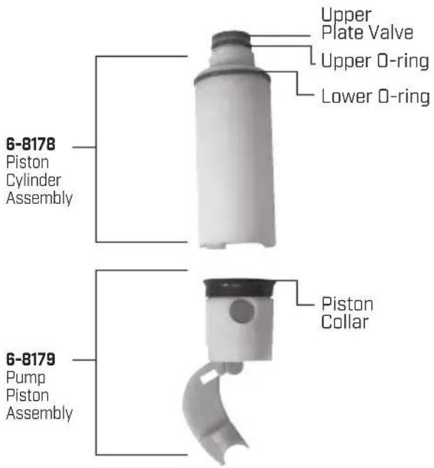
DISASSEMBLING AND REPAIRING THE PUMP ASSEMBLY
text_image
In-Tank FilterFigure 1
natural_image
Close-up of a mechanical testing setup with a white cylindrical component being handled by a tool (no visible text or symbols)Figure 2
natural_image
Close-up of a white robotic arm gripping a small mechanical component (no visible text or symbols)Figure 3
natural_image
Close-up of a black mechanical component with a metallic wrench inserted (no visible text or symbols)Figure 4
natural_image
Close-up of a white plastic mechanical component with a curved arrow indicating rotation (no text or symbols visible)Figure 5
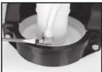
- Release the pressure from the sprayer and remove all liquid from both the pressure chamber and tank.
- Remove the In-tank filter from the pressure chamber [fig. 1].
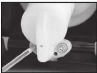
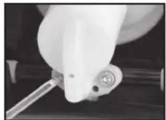
- Remove hose (fig. 2).
- Remove 2 bolts attaching the pivot lever to the pump shaft and remove piston assembly (fig. 3).
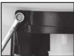
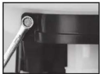
- Remove the 2 bolts holding back spine/frame [fig. 4], and the back spine/frame will come off.
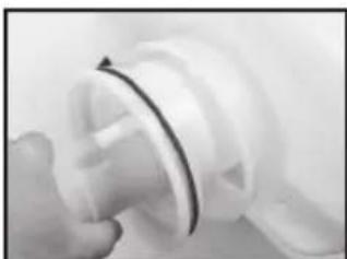
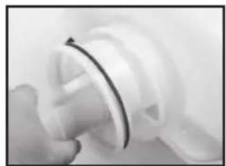
- Rock the pressure chamber back and forth and push down to free it from the tank (fig 5). Once freed the entire pump assembly can be removed.
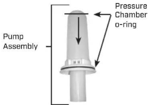
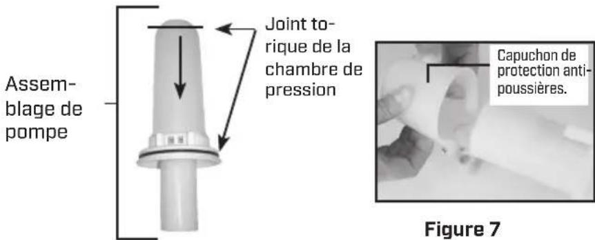
- The pressure chamber o-ring can be replaced. DO NOT stretch the o-ring over the bottom flange. Assemble the o-ring over the top of the chamber. Apply petroleum jelly to the o-ring before reinstalling pump assembly into the tank [fig. 6].
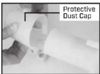
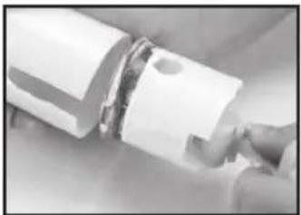
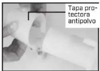
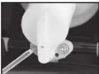
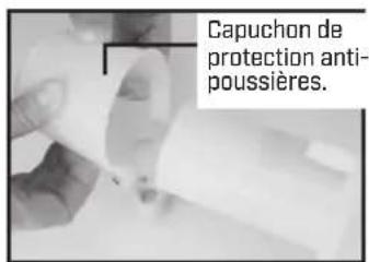
- To inspect piston and/or piston cylinder components, remove protective dust cap (fig. 7).
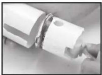
- Remove the piston (fig. 8) and inspect for wear. See next page for further repair instructions.
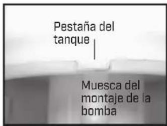
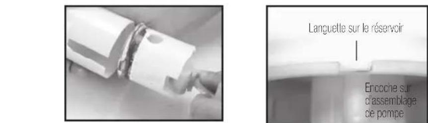
- Reassemble in reverse of removal. Note: there is a notch/tab combination in the pump assembly/tank to be used for alignment (fig. 9).
text_image
Pump Assembly Pressure Chamber o-ringFigure 6
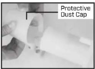
text_image
Protective Dust CapFigure 7
natural_image
Close-up of a hand holding a white cylindrical object with metallic brackets (no visible text or symbols)Figure 8 Figure 9
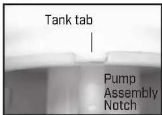
text_image
Tank tab Pump Assembly NotchREPAIRING THE PISTON/CYLINDER ASSEMBLY
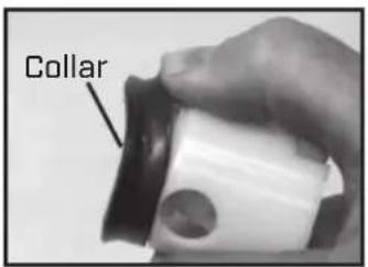
text_image
CollarFigure 1
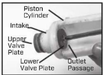
text_image
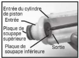
Piston Cylinder Intake Upper Valve Plate Lower Valve Plate Outlet PassageFigure 2
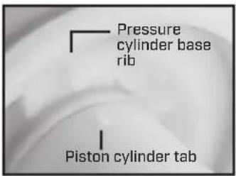
text_image
Pressure cylinder base rib Piston cylinder tabFigure 3
natural_image
Close-up of a hand holding a white cylindrical object with a metallic clip, possibly a mechanical or electronic component (no visible text or symbols)Figure 4
text_image
Protective Dust CapFigure 5
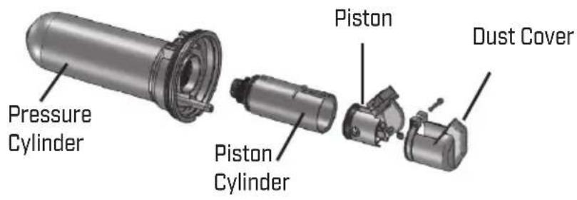
text_image
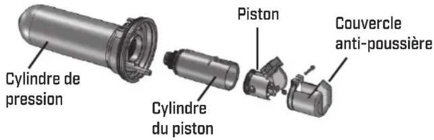
Pressure Cylinder Piston Cylinder Piston Dust Cover- Remove the piston cylinder assembly by turning the piston cylinder counter-clockwise when viewing the sprayer from the bottom. Caution: The piston cylinder may have sharp edges.
- Check for vertical scratches on the inside of the piston cylinder and the piston. If one or both are scratched replace them.
- To replace the collar, push it off of the crown of the piston with your thumb. You will see form fitted slots to install the new collar on to the piston crown (fig.1).
- There are 2 valve plates on the piston cylinder, one on the inside of the cylinder and one on the outside top. The valve plates are held in place with a screw and washer and can be removed and replaced using a Phillipshead screw driver. The 2 o-rings can be removed and replaced as well. Ensure that the o-rings are positioned in the o-ring grooves in the piston cylinder.
- Grease the 2 D-rings on the piston cylinder (do not get any grease on the valve plate) and screw the piston assembly into the pressure cylinder base. Screw the piston cylinder clockwise until tight and the bottom O-ring is no longer visible. When properly placed, the tab on the piston cylinder will line up with the rib on the pressure cylinder base (Fig. 3).
- Apply Petroleum jelly to the inside of the piston cylinder wall and on the collar, and reinstall the piston assembly into the piston cylinder.
- Insert the piston at an angle with the leading edge of the collar placed over the slot in the piston cylinder. Bolt the piston assembly to the pump shaft using the lever bolts.
- Replace the protective dust cap. Tighten the nut and bolt.
DISASSEMBLING AND REPAIRING THE SHUT OFF VALVE
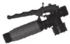
Figure 1
natural_image
Mechanical device with a pointed tool and lever assembly (no visible text or symbols)Figure 2
text_image
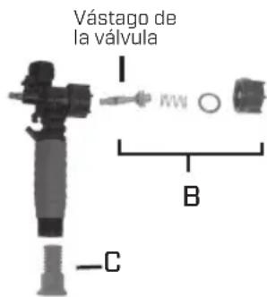
Valve Stem I B CFigure 3
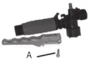
1) Assembled shut-off valve (Figure 1).
2) Remove the retaining pin [A] (Figure 2) place the notched end of the retaining pin on a hard surface and push down. Remove the retaining pin and slide the handle off the valve.
3) Remove the retaining nut (o-ring attached), spring, and valve stem (B) (Figure 3). Replace worn parts. Lubricate the O-rings and reassemble by reversing the steps above. Place the handle groove in the slotted area of the valve stem and make sure the locking clip is positioned in the neutral position (see "Helpful Spraying Information" section). Insert the retaining pin. Push down on the handle a few times to distribute the lubricant evenly. Check filter (C) in end of shut-off valve for debris. Remove filter and flush with water to clean out.
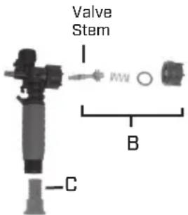
REPLACEMENT PARTS ORDER INFORMATION
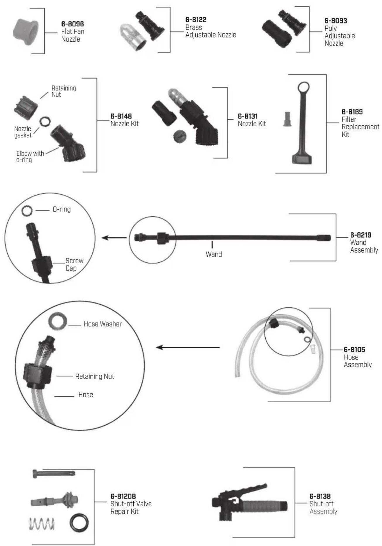
REPLACEMENT PARTS ORDER INFORMATION
text_image
6-8178 Piston Cylinder Assembly Upper Plate Valve Upper O-ring Lower O-ring 6-8179 Pump Piston Assembly Piston Collar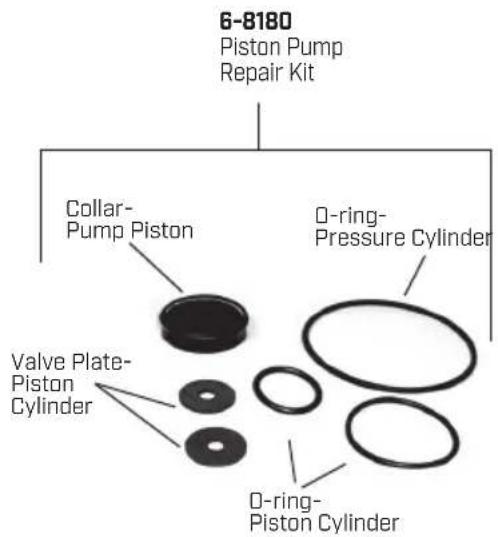
text_image
6-8180 Piston Pump Repair Kit Collar- Pump Piston O-ring- Pressure Cylinder Valve Plate- Piston Cylinder O-ring- Piston Cylinder
Elbow O-ring
Hose Gasket
Nozzle Gasket Wand O-ring
6-8153
D-ring Kit
natural_image
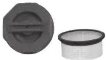
Two plastic filter components: a circular cap with a side slot and a rectangular filter with a mesh pattern (no text or symbols visible)6-8146-2
Filter Basket & Cap
natural_image
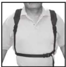
Person wearing a white shirt and black belt with straps (no visible text or symbols)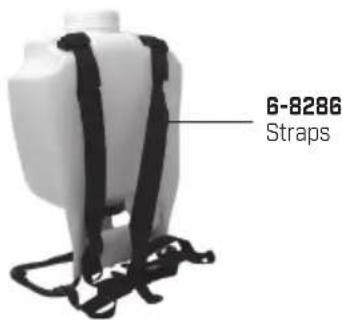
text_image
6-8286 Straps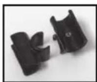
6-8152
Wand Clips
Congratulations!
You have just purchased a quality Chapin product.
Register Your Sprayer Online@ www.chapinmfg.com/warranty.asp
Chapin International, Inc
PULVERIZADOR DE MOCHILA PROSERIES
MANUAL DE USO Y CUIDADO
ADVERTENCIA
Failure to do so may result in damage to property and/or person.
natural_image
Exterior view of a modern agricultural sprayer with a black lever and spray bottle (no text or symbols visible on the device itself)natural_image
Close-up of a mechanical component with bolts and a curved handle (no visible text or symbols)natural_image
Close-up of a mechanical assembly with bolts and wires (no visible text or symbols)natural_image
Close-up of a pipe fitting with two bolts attached (no text or symbols visible)natural_image
Close-up of a white spray bottle with black handle and white spray tube (no text or symbols visible)Ensamblaje completo
natural_image
Close-up of a hand holding a black plastic clip with a curved handle, no visible text or symbolsnatural_image
Close-up of a mechanical component with a cylindrical rod inserted into a stepped base (no visible text or symbols)natural_image
Close-up of a mechanical component with textured surface and curved edge (no visible text or symbols)natural_image
Close-up of a black mechanical component with mesh texture, possibly a filter or mesh array (no visible text or symbols)natural_image
Mechanical component with a rotating lever and threaded shaft (no visible text or symbols)Figura 1 Figura 2 Figura 3
natural_image
Close-up of a mechanical testing setup with a white cloth sample being handled by a tool (no visible text or symbols)Figura 2
natural_image
Close-up of a white robotic arm gripping a small mechanical component (no visible text or symbols)Figura 3
natural_image
Close-up of a mechanical component with a wrench inserted, no visible text or symbolsFigura 4
natural_image
Close-up of a hand holding a white plastic mechanical component with a curved arrow indicating rotation (no text or symbols visible)Figura 5
natural_image
Close-up of a hand holding a white cylindrical object with a metallic clip, no visible text or symbolsFigura 8 Figura 9
natural_image
Close-up of hands holding a white cylindrical object with a metallic ring (no visible text or symbols)Figura 4
text_image
Tapa protectora antipolvoFigura 5
natural_image
Mechanical device with lever and attached component, labeled A (no text or symbols on the device itself)Figura 2
text_image
Vástago de la válvula I B CFigura 3
Failure to do so may result in damage to property and/or person.
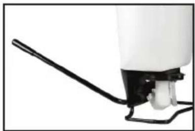
natural_image
Exterior view of a modern agricultural sprayer with a black lever and spray bottle (no text or symbols visible on the device itself)
natural_image
Close-up of a mechanical component with bolts and a curved handle (no visible text or symbols)natural_image
Close-up of a mechanical assembly with bolts and tubing (no visible text or symbols)natural_image
Close-up of a black pipe with two bolts and a curved cable (no text or symbols visible)Figure 5 Droit
natural_image
Close-up of a white spray bottle with black handle and white plastic tip, no visible text or symbolsAssemblage terminé
INSTALLER LA BANDOULIÈRE
natural_image
Close-up of a black plastic clip holding a flexible cable (no visible text or symbols)PORTE-LANCE
natural_image
Close-up of a mechanical component with a cylindrical rod inserted into a stepped base (no visible text or symbols)SYSTÈME DE FILTRAGE À 3 ÉTAPES
natural_image
Close-up of a mechanical component with a textured spherical part, possibly a tool or device (no visible text or symbols)natural_image
Close-up of a black mechanical component with textured surface (no visible text or symbols)Figure 1 Figure 2 Figure 3
natural_image
Close-up of a mechanical testing setup with a white cylindrical component mounted on a black circular base, no visible text or symbols.Figure 2
natural_image
Close-up of a white robotic arm gripping a small mechanical component (no visible text or symbols)Figure 3
text_image
Assemblage de pompe Joint to- rique de la chambre de pression Capuchon de protection anti- poussières. Figure 7Figure 6
text_image
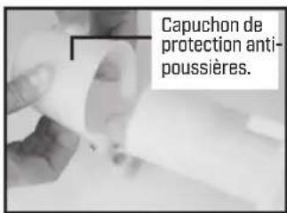
Capuchon de protection anti- poussières.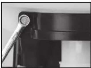
natural_image
Close-up of a mechanical component with a metallic tool inserted, no visible text or symbolsFigure 4
natural_image
Close-up of a white plastic mechanical component with a curved black line indicating rotation (no text or symbols visible)Figure 5
RÉPARATION DE L'ASSEMBLAGE PISTON/CYLINDRE

text_image
CollierFigure 1
natural_image
Close-up of a hand holding a white cylindrical object with a metallic ring, no visible text or symbolsFigure 4
text_image
Capuchon de protection anti- poussières.Figure 5
text_image
Cylindre de pression Cylindre du piston Piston Couvercle anti-poussièrenatural_image
Black-and-white photo of a firearm with lever and barrel (no visible text or symbols)Figure 1
natural_image
Mechanical assembly diagram showing a cylindrical component with attached parts and a labeled section A (no text or symbols on the main components)Figure 2
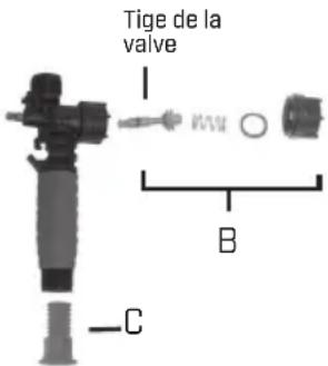
text_image
Tige de la valve B CFigure 3