63950 - Backpack sprayer Chapin - Free user manual and instructions
Find the device manual for free 63950 Chapin in PDF.

User questions about 63950 Chapin
0 question about this device. Answer the ones you know or ask your own.
Ask a new question about this device
Download the instructions for your Backpack sprayer in PDF format for free! Find your manual 63950 - Chapin and take your electronic device back in hand. On this page are published all the documents necessary for the use of your device. 63950 by Chapin.
USER MANUAL 63950 Chapin
Failure to do so may result in damage to property and/or person.

MIXES™
ON EXIT

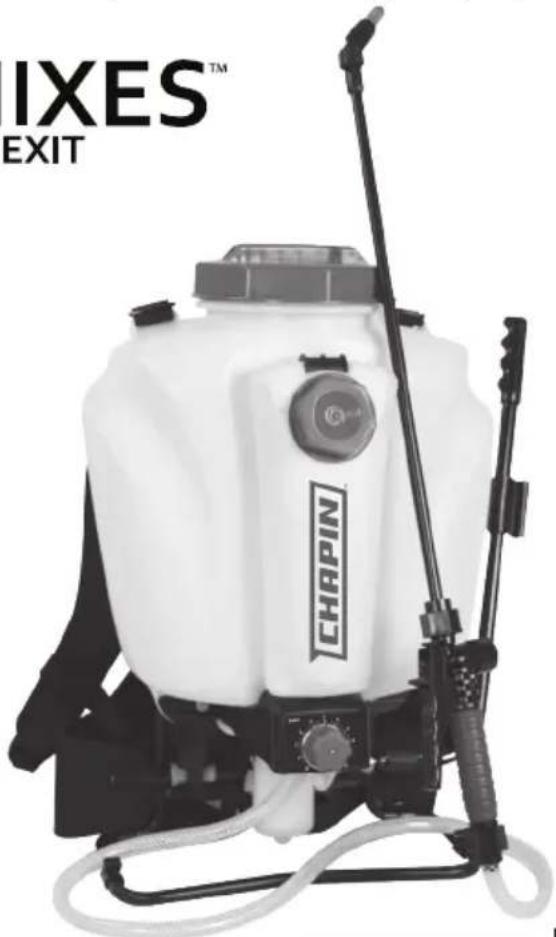
natural_image
Exterior view of a white spray sprayer with 'CHAPIN' branding and 'IIXES™ EXIT' text (no other signage or symbols)
See website for warranty detail
Model 63950·4G/15L
CONGRATULATIONS!
YOU HAVE JUST PURCHASED A QUALITY CHAPIN PRODUCT.
REGISTER YOUR PRODUCT ONLINE @ WWW.CHAPINMFG.COM
VISIT US ON THE INTERNET: WWW.CHAPINMFG.COM
BEFORE RETURNING THIS PRODUCT FOR ANY REASON, PLEASE CALL:
1-800-950-4458
When calling, please have the following information available: Sales receipt & model number. This number connects you directly with the manufacturer of this product. Our Technical Support Team will be happy to help you with any assembly, troubleshooting and replacement information you may need.
WARNING
WARNING: IMPROPER USE OR FAILURE TO FOLLOW INSTRUCTIONS CAN RESULT IN EXPLOSIVE FAILURE CAUSING SERIOUS EYE OR OTHER INJURY.
For safe use of this product you must read and follow all instructions. Do not leave a pressurized sprayer in the hot sun. Heat can cause pressure build-up resulting in possible explosion. Do not store or leave solution in tank after use. Always wear goggles, gloves, long sleeve shirt, long pants and full foot protection when spraying. Never use any tool to remove pump if there is pressure in the pressure chamber. Never pressurize sprayer by any means other than the original pump. Do not attempt to modify this sprayer. Replace parts only with manufacturer's original parts.
Never spray flammable, caustic, acidic, chlorine, bleach or other corrosive solutions or heat, pressure, or gas producing chemicals. Always read and follow chemical manufacturer's instructions before use with this sprayer as some chemicals may be hazardous when used with this sprayer.
SK 1158-1
CAUTION
- PRE-USE CHECK: Before each use check tightness of hose nut to be sure hose is securely attached to the shut-off assembly. Ensure hose is securely attached to the tank by tightening hose clamp if necessary.
Ensure that all nozzle and wand connections are tight. Ensure the large pump clamp is tight. Ensure the 2 bolts used to attach the pump lever to the pump shaft are tight. - Do Not exceed a tank solution temperature of 120^ / 49^ .
NOTE: The tank and hose may have residual water in it due to quality testing performed on the sprayer.
"Always review all instructions with respect to any liquid or other material before placing inside this product, and always abide by such instructions. Always label this product with the full name of any liquid or other material placed inside this product.
Always ensure all old liquid or other materials are removed from this product before placing any different liquid or other material in this product.
DISCLAIMER: The Manufacturer is not responsible for, and assumes no liability with respect to, any liquid or other material placed inside this product. All liquids and other materials placed inside this product, and the use of any such liquids and other materials with this product, are at your own risk."
APPLICATIONS & USE FOR YOUR SPRAYER
Avoid using a sprayer for general cleaning purposes if plant protection or herbicide chemicals have already been used in the sprayer. If a sprayer has been used for plant protection or as an herbicide, clean the sprayer completely (see cleaning section) before using.
Plant Food: Use different spray patterns for optimum foliage feeding or for fungicide and pesticide application.
Herbicides: Reduce weeds and unwanted plants but avoid using the same sprayer for plant feeding or protection without thoroughly cleaning (see cleaning section) the sprayer first.
General Household Use: Apply detergents, cleaning solutions, warm water (do not exceed 120^ F/49°C) or nontoxic household cleaning chemicals for carpets, floors, walls, glass, counter tops and ceilings. DO NOT use sprayer that has been used with herbicides, pesticides or other toxic chemicals for household applications.
General Outdoor Use: Use the sprayer for cleaning windows or with a detergent for general purpose cleaning.
SPRAYER COMPONENTS & USE INFORMATION
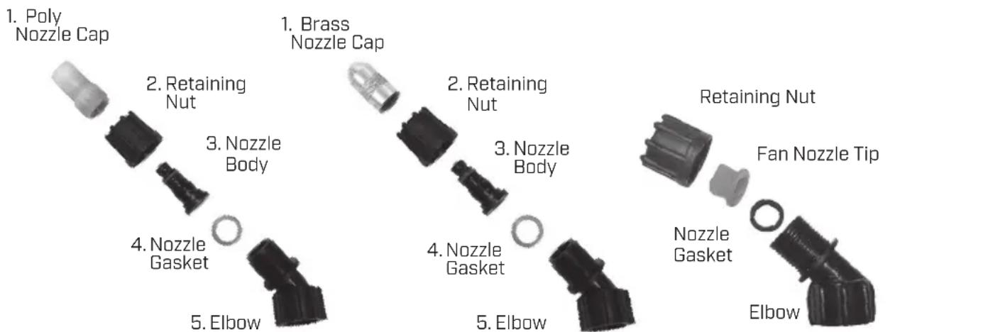
NOZZLE ASSEMBLY
Figure 1-2
Unscrew the nozzle cap (1) from the nozzle body (3) with retaining nut (2) fastened tightly to the elbow (5). Unscrew the retaining nut (2). Push the nozzle body (3) with the nozzle gasket (4) out of the retaining nut (2). To reinstall the nozzle, reverse the above instructions.
Figure 3
Unscrew the retaining nut from the elbow and push the fan nozzle tip and gasket out of the retaining nut. To reinstall the nozzle, reverse the above instructions.
text_image
1. Poly Nozzle Cap 2. Retaining Nut 3. Nozzle Body 4. Nozzle Gasket 5. Elbow 1. Brass Nozzle Cap 2. Retaining Nut 3. Nozzle Body 4. Nozzle Gasket 5. Elbow Retaining Nut Fan Nozzle Tip Nozzle Gasket ElbowFigure 3 Figure 2 Fi
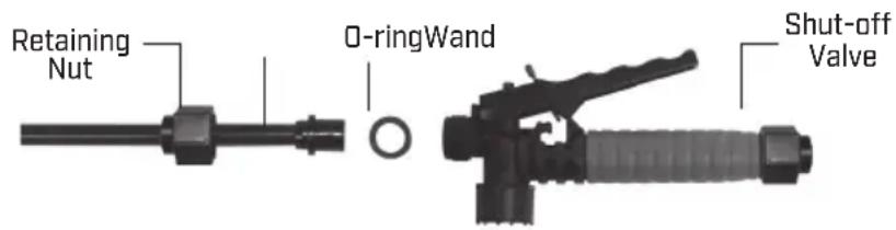
WAND ASSEMBLY
- Make sure the o-ring is installed on the end of the wand. Insert the wand into shut-off valve.
- Turn and tighten the retaining nut clock-wise onto the shut-off valve.
text_image
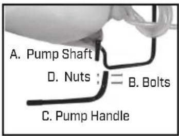
Retaining Nut O-ringWand Shut-off ValveINSTALLING THE PUMP HANDLE
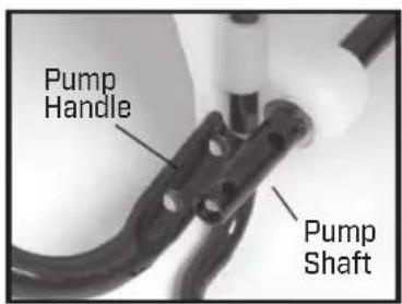
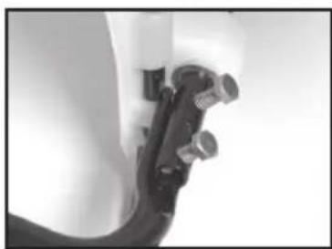
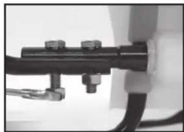
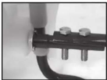
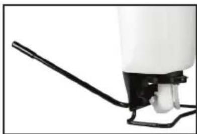
The pump handle can be mounted on either side of the pump shaft [A]. To install the pump handle place the handle [C] over the shaft [A] aligning the pump handle holes and shaft holes. Slide the bolts [B] through the aligned holes as shown in figure 3. Tighten nuts [D] to bolts. There are holes in the pump handle to allow for either left (fig.2-4) or right (fig.5) hand mounting.
text_image
A. Pump Shaft D. Nuts : = B. Bolts C. Pump Handle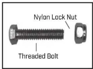
text_image
Nylon Lock Nut Threaded BoltFigure 1 Figure 2
text_image
Pump Handle Pump ShaftLine up holes
natural_image
Close-up of a mechanical pipe fitting with multiple valves (no visible text or symbols)Figure 3 Slide bolts through holes
natural_image
Close-up of a mechanical assembly with black components and connectors (no visible text or symbols)Figure 4 Tighten nut to bolt
natural_image
Close-up of a mechanical pipe fitting with two bolts and a screw, no visible text or symbolsFigure 5 Right Hand
natural_image
Close-up of a white spray gun with black handle and white spray bottle (no text or symbols visible)Completed Assembly
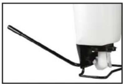
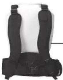
INSTALLING THE SHOULDER STRAP
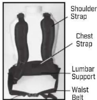
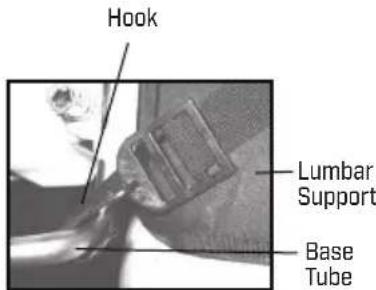
The backpack strap is provided with multiple features including shoulder strap, chest strap, waist belt and lumbar support. (figure 1). The top the shoulder strap is attached to the top of the tank and is removable. The hook from the lumbar support attaches to the base tube on the bottom of the tank (figure 2).
text_image
Shoulder Strap Chest Strap Lumbar Support Waist BeltFigure 1 Strap Assembly
text_image
Hook Lumbar Support Base TubeFigure 2 Hook Attachment
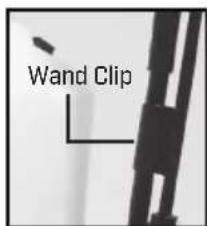
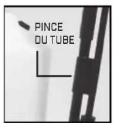
WAND HOLDER
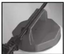
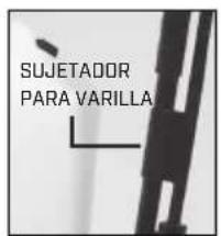
The wand easily snaps into cap handle or can be attached to the pump handle using the wand clip.
natural_image
Close-up of a mechanical component with a cylindrical rod inserted into a rectangular housing (no visible text or symbols)Or
text_image
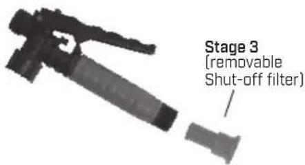
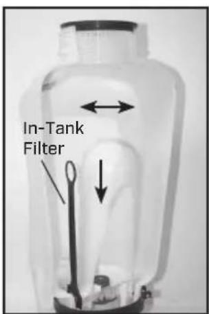
Wand Clip3 STAGE FILTERING SYSTEM
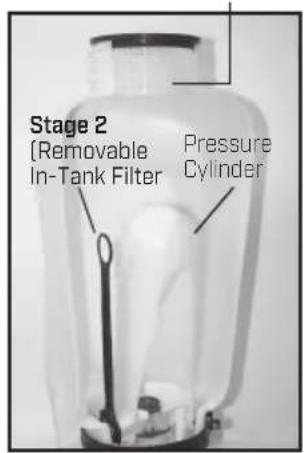
This backpack sprayer is equipped with a 3 stage filtering system (see figure 1). Stage 1 is a filter basket incorporated into the tank opening where fluid is added. Stage 2 filter is located at the inlet of the pressure cylinder. Stage 2 is a removable In-Tank filter. Stage 3 is a removable filter incorporated into the shut-off assembly. Periodic cleaning of these filters is recommended to insure consistent fluid flow through the sprayer. This will also reduce sprayer component wear.
The stage 3 filter is a removable filter incorporated into the inlet side of the shut-off valve (see section "disassembling and repairing the shut-off valve"). Make sure pressure is released before detaching the hose from the shut-off. It is best to have no or minimal fluid in the pressure cylinder before removing and reinstalling the stage 3 shut-off filter as fluid can leak from the hose.
Stage 1 [Filter basket]
text_image
Stage 2 (Removable In-Tank Filter Pressure CylinderFigure 1
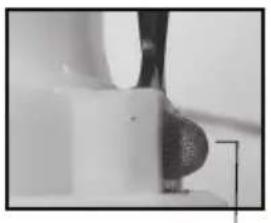
Figure 2 Stage 2 [removable In-tank filter]
natural_image
Close-up of a mechanical component or tool interacting with a surface (no visible text or symbols)Guide edge facing away from pressure cylinder
natural_image
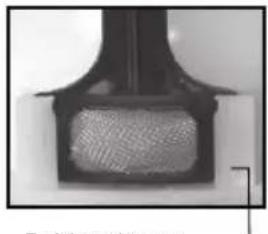
Close-up of a black mechanical component with a textured inner surface (no visible text or symbols)Guide edge on pressure cylinder
text_image
Stage 3 (removable Shut-off filter)FILLING SPRAYER TANK
Make sure the filter basket is in place to keep debris from entering the tank. Fill sprayer tank with water.
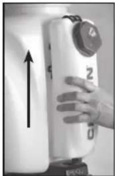
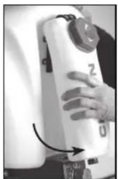
FILLING CHEMICAL TANK
Push chemical tank up (figure 1), then pull out (figure 2).
Place chemical tank on a flat surface and fill with desired amount of chemical.
Always follow the Chemical manufacturer's instructions. Snap chemical tank back onto sprayer.
natural_image
Hand holding a white cylindrical device with a black control knob and upward arrow, no visible text or symbolsFigure 1
natural_image
Close-up of a hand holding a white cylindrical device with a black label 'Z' and arrow pointing to it (no readable text or symbols beyond the label)Figure 2
BASIC USE OF MIXES ON EXIT™ SETTING ADJUSTMENT
Set sprayer knob adjustment (pull to turn) to desired amount of concentrate sprayed per gallon. Fill Chemical tank with exact amount of chemical to cover the square footage per Chemical manufacturer's instructions. Example: 1 ounce for 10 square feet. Evenly spray and cover the desired 10 square foot area until concentrate tank is empty. Note: Setting 1 will mix less chemical with water - setting 7 will allow more concentrate to be mixed with water when spraying. The water is the vehicle in which the chemical is being delivered. As long as you cover the desired predetermined area with the appropriate amount of chemical the amount of water is inconsequential. Setting the mix ratio helps you control how quickly the chemical is delivered per gallon.
[Use this process for calibrating your mix ratio settings]
1) Fill the concentrate tank and backpack tank - both with water.
2) Weigh the Concentrate tank and record the weight.
3) Set the dial to the desired position (example: set to 1 for 1 ounces per gallon).
4] Weigh your empty bucket [record the weight for future reference if your scale doesn't have a tare function].
5) Keeping the bucket on the scale, spray 1 gallon of water (adding an additional 8.34 lbs to the empty weight of your bucket).
6) As you spray, keep your pump strokes consistent for most accurate measurement.
7) Remove the concentrate tank from the backpack sprayer and weigh the tank with it's remaining chemical in the tank.
8) Subtract the current weight of concentrate tank from the weight recorded in step 2.
9) Calculate the mix ratio using the following equation:
$$ \text { Mix Ratio } = \frac {1 2 7 . 9 3 5 6}{\left( \begin{array}{c} \text { TOTAL WT OF WATER } \ \text { CHANGE IN WT OF } \ \text { CONCENTRATE TANK } \end{array} \right)} - 1 $$
10] If results are slightly off from the expected mix ratio,
set knob -/+ to accommodate variance and retest to confirm accuracy.
Once confirmed note setting that provides exactly 1 ounce per gallon.
11) Repeat as needed for a range of settings
NOTE:
- Be sure to pull and turn the mix ratio dial when choosing your setting.
- Always follow chemical manufacturer's instructions.
- When not spraying, set mix ratio dial to zero.
- Approximate mix ratios based on chemical concentrates with approximate viscosity to water while pumping at a rate of 60 beats per minute.
- Pumping faster than 60 BPM will result in higher mix ratios and pumping slower will result in lower mix ratios.
SETTINGS GUIDE
| Setting Dunces Per Gallon | |
| 1 | 0.5 oz. per gallon |
| 2 | 2.0 oz. per gallon |
| 3 | 3.5 oz. per gallon |
| 4 | 5.0 oz. per gallon |
| 5 | 6.0 oz. per gallon |
| 6 | 7.0 oz. per gallon |
| 7 | 8.0 oz. per gallon |
| 8 | 8.5 oz. per gallon |
| 9 | 9.0 oz. per gallon |
| 10 | 9.5 oz. per gallon |
HELPFUL SPRAYING INFORMATION
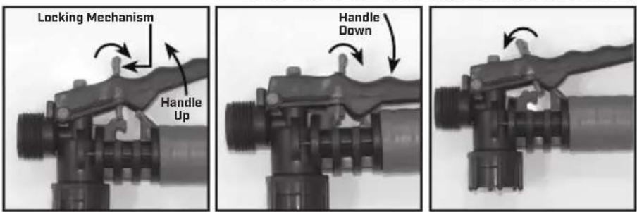
Use RAPID pump strokes to prime the pump. You will know the pressure chamber is filling with liquid when you feel firm resistance from the pump. The air in the pressure chamber is compressed from repeated strokes. By pressing the hand lever on the shut-off, the valve opens. For safety lock-off feature (no-spraying), pull up on handle and move red locking mechanism into lock-off position as shown in fig. 1. To disengage, pull up on handle and return red locking mechanism to neutral position as in fig. 3. For lock-on feature (continuous spraying), push down on handle and move red locking mechanism into lock-on position as shown in fig. 2. To disengage, push down on handle and return red locking mechanism to neutral position as shown in fig. 3.
LOCK-ON POSITION NEUTRAL POSITIONLOCK-OFF POSITION
text_image
Locking Mechanism Handle Up Handle DownFigure 1 Figure 2 Figure 3
For easy pump action use the END of the pump handle. The amount of liquid delivered during spraying depends on the rate of pump stroke. The fan nozzle tip is rated at .4 gpm at 40psi. This is the nominal operating pressure of the sprayer.
Note: If you experience a rapid drop in pressure, drain the sprayer completely and pump the handle with an empty tank. The pressure chamber will fill with the required volume of air to repressurize. Perform this procedure from time to time as routine maintenance.
CLEANING
1] Always empty the sprayer and clean the tank thoroughly after each use.
2) Pump the sprayer handle until all of the contents and air exit through the nozzle (minimum of 30 strokes).
3) Fill tank half way with water and pump the water out as explained in step 2 (repeat several times as necessary).
Other Cleaning Hints:
- Improper spray distribution usually means the nozzle is clogged, remove the nozzle and clean it.
- Soap can be added to the water to clean the tank.
- Do not use strong cleaning agents or abrasives.
- If you use a chemical agent to clean the tank follow the manufacturer's recommendations for the disposal of the waste water.
- Follow the chemical manufacturers instructions for clean up.
STORING / MAINTAINING YOUR SPRAYER
- The sprayer should be stored out of direct sunlight in a cool dry space.
- Before freezing weather make sure to drain all liquid in the tank, pump, pressure cylinder, hose, shut-off valve, wand and nozzle, to avoid liquid expansion and cracking in the sprayer components (See “Cleaning” section). Lock the shut-off valve in the “open” position.
- When service is required call your nearest dealer and always insist on original manufactured replacement parts.
- Inspect the hose, wand, pump, tank and shut-off valve for wear, damage or leaks on a regular basis and repair defects promptly.
TROUBLE SHOOTING YOUR SPRAYER
Symptom Possible Reason Correction
| Difficulty actuating the pump lever and/or pump handle moves itself back up. | Upper valve plate sticks Clean or replace valve plate | |
| Piston cylinder outlet passage clogged Clean piston cylinder outlet passage | ||
| Little or no resistance during repeated pumping - no pressure. | Damaged/worn/dirty/upper and or lower valve plate | Clean or Replace Valve Plate |
| Damaged /worn upper o-ring on piston Replace O-ring | ||
| Piston Collar or piston cylinder assembly is worn | Replace Collar or Piston cylinder assembly | |
| Too much resistance after just a few pumping strokes but pressure only lasts briefly. | Not enough air cushion in the pressure chamber | Release pressure in pressure chamber.Remove the hose & drain pressure chamber. Reconnect the hose. |
| Upper valve plate damaged/worn/dirty Clean or replace upper valve plate | ||
| Upward pumping action is more difficult and/or pump handle moves itself backdown. | Vent hole is clogged Clear the vent hole in cap. | |
| Lower valve plate sticks Clean or replace the valve plate | ||
| Clogged filter Clean in tank filter | ||
| Piston cylinder intake clogged Clean piston cylinder intake | ||
| When the handle is pulled up it moves itself back down | Valve Plate sticking Clean or replace valve plate | |
| Leaks at Piston Cylinder Damaged/worn/Dirty Collar Clean or Replace Piston Collar | ||
| Damaged Piston Cylinder Replace Piston Cylinder | ||
| Damaged Piston | Replace Piston | |
| Shut-off leaks | Connections loose | Tighten connection. |
| Worn or damaged shut-off | Rebuild or replace the shut-off valve. | |
| Wand assembly leaks | Connections loose | Tighten connection. |
| Damaged or worn o-ring/gasket | Replace o-ring/gasket. | |
| Nozzle assembly leaks | Connections loose | Tighten connection. |
| Damaged or worn o-ring/gasket | Replace o-ring/gasket. | |
| Leak between pump assembly and tank | Pump clamp loose | Tighten clamp. |
| O-ring worn or damaged | Replace pressure chamber o-ring. | |
| Hose leaking at tank outlet | Hose clamp loose | Tighten clamp. |
| Hose leaking at shut-off Connection loose Tighten retaining nut. | ||
| Chemical tank doesn't stay in place | Bracket Spring is not tight | Tighten spring tension bolt |
DISASSEMBLING AND REPAIRING THE PISTON PUMP
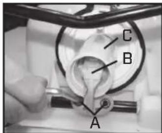
text_image
C B AFigure 1
natural_image
Close-up of hands holding a small electronic device (no visible text or symbols)Figure 2
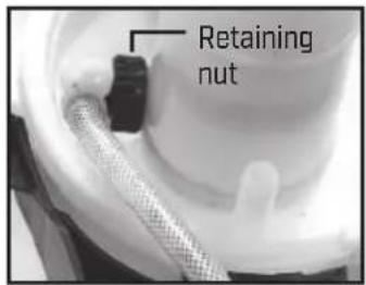
text_image
Retaining nutFigure 3
natural_image
Close-up of a hand holding a white cylindrical object, possibly a mechanical component or tool (no visible text or symbols)Figure 4
natural_image
Close-up of a hand holding a white plastic tool with a cylindrical component (no visible text or symbols)Figure 5
text_image
CollarFigure 6
1) Depending on your model, remove the cotter pin or bolts that hold the pump handle to the pump shaft.
2) With the pump facing towards you lay the sprayer on its back (Fig. 1). Loosen the hose clamp and remove the sprayer hose. Caution: there could be residual liquid in the hose and pressure cylinder. Remove the nut and bolt from the protective cap using an allen wrench. Once the bolt has been removed, remove the cover. Rotate the pump shaft in order to reach the lever bolts (A) that connect the piston assembly (B) to the pump shaft. Using an allen wrench, remove the lever bolts. Pull the piston out of the piston cylinder (C).
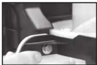
3) Remove the 2 bolts that hold the frame assembly to the sprayer tank (Fig.2). Use a socket wrench on both the bolt and nut to loosen (Fig.2). Once these bolts are removed, the frame assembly should separate from the tank.
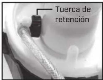
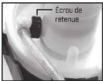
4) With a pair of pliers, reach into the pump cylinder to loosen the black plastic retaining nut (Fig.3) to remove the detach the hose.
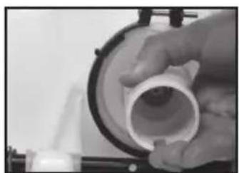
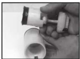
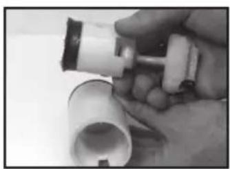
5) Remove the piston cylinder assembly by twisting the cylinder counter clockwise (Fig. 4). This may require a strap wrench or large pair of pliers. Careful not to damage the cylinder if using pliers.
6) Check both the Piston and the inside of the piston cylinder for vertical stretches. If scratched, replace the piston.
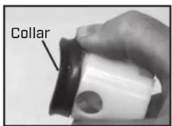
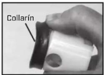
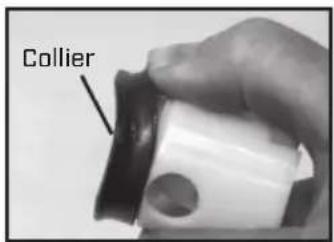
7) To replace the collar, push it off of the crown of the piston with your thumb. You will see form fitted slots to install the new collar on to the piston crown (fig. 6).
text_image
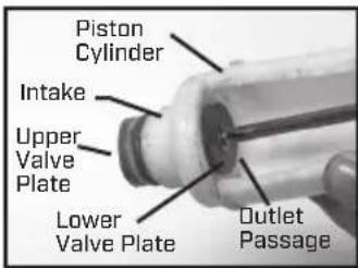
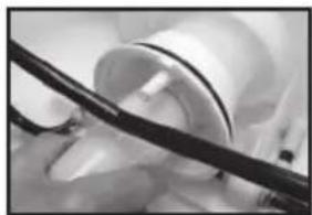
Piston Cylinder Intake Upper Valve Plate Lower Valve Plate Outlet PassageFigure 7
natural_image
Close-up of a gloved hand holding a small metallic object with an arrow pointing upward, next to a black mechanical component (no visible text or symbols)Figure 8
text_image
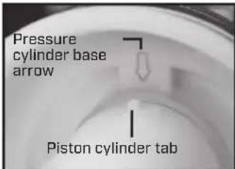
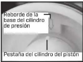
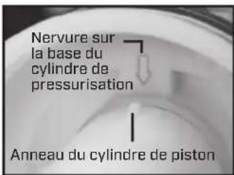
Pressure cylinder base arrow Piston cylinder tabFigure 9
natural_image
Close-up of hands using a tool to adjust or install a small object (no visible text or symbols)Figure 10
natural_image
Close-up of hands adjusting a wristwatch (no visible text or symbols)Figure 11
text_image
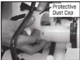
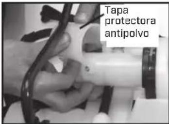
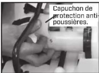
Protective Dust CapFigure 12
8) There are 2 valve plates on the piston cylinder, one on the inside of the cylinder and one on the outside top. The valve plates are held in place with a screw and washer and can be removed and replaced using a Phillipshead screw driver. The 2 o-rings can be removed and replaced as well. Insure that the o-rings are positioned in the o-ring grooves in the piston cylinder (Fig. 7).
9) Reassemble frame assembly to the sprayer tank. Use a socket wrench on both the bolt and nut to tighten (Fig. 8).
10] Reassemble the black plastic retaining nut to the piston cylinder [Fig. 3].
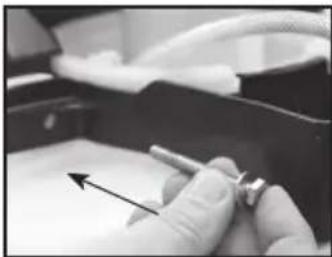
11] Grease the 2 D-rings on the piston cylinder (do not get any grease on the valve plate) and screw the piston assembly into the pressure cylinder base. Screw the piston cylinder clockwise until tight and the bottom O-ring is no longer visible. When properly placed, the tab on the piston cylinder will line up with the arrow on the pressure cylinder base (Fig.9).
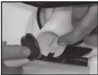
12] Apply Petroleum jelly to the inside of the piston cylinder wall and on the collar, and reinstall the piston assembly into the piston cylinder (Fig.10).
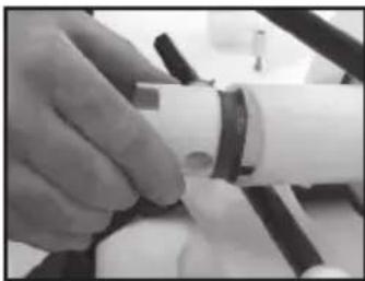
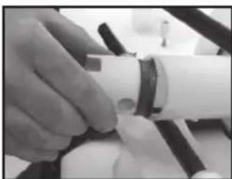
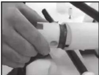
13) Insert the piston at an angle with the leading edge of the collar placed over the slot in the piston cylinder (Fig. 11). Bolt the piston assembly to the pump shaft using the lever bolts (Fig. 1).
14] Replace the protective dust cap (Fig. 12). Tighten the nut and bolt. Reinstall the pump handle (see install pump handle). Replace the hose and firmly secure the hose clamp in place.
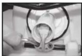
DISASSEMBLING AND REPAIRING THE PUMP ASSEMBLY
- Release the pressure from the sprayer and remove all liquid from both the pressure chamber and tank.
- Loosen hose clamp and remove hose.
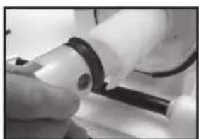
- Remove the In-tank filter from the pressure chamber.
- Remove 2 bolts attaching the pivot lever to the pump shaft and remove piston assembly [fig. 2a & 2b].
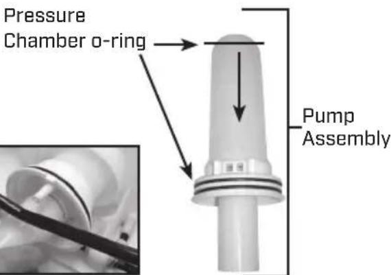
- Remove large clamp holding the pressure chamber and tank together (fig 1).
- Rock the pressure chamber back and forth and push down to free it from the tank (fig 1).
- Once freed the entire pump assembly can be removed by maneuvering it through the base frame (fig 3a & 3b).
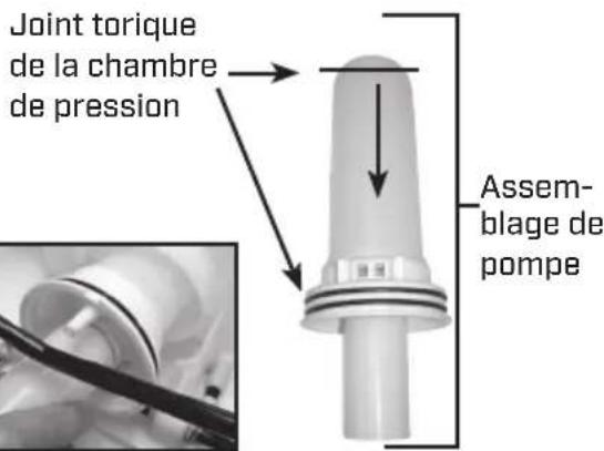
- The pressure chamber o-ring can also be replaced. DO NOT stretch the o-ring over the bottom flange.
Assemble the o-ring over the top of the chamber. Apply petroleum jelly to the o-ring before reinstalling pump assembly into the tank (fig. 3b).
- Reassemble by attaching components in reverse order.
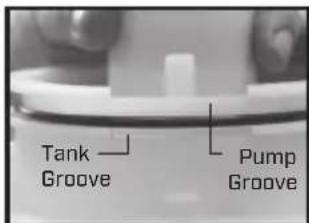
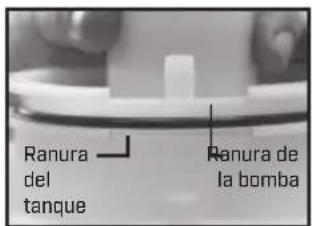
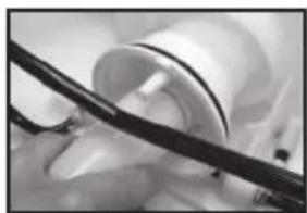
NOTE: When attaching frame assembly, align tank groove and pump groove [Fig. 4].
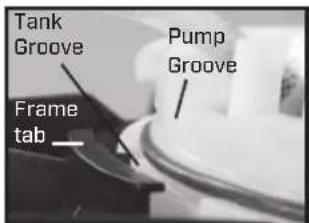
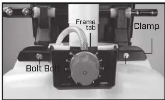
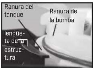
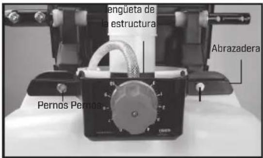
Lock in place with frame tab (Fig. 5) to secure all 3 components. Secure frame assembly with 2 bolts (Fig. 6).
text_image
In-Tank FilterFigure 1
natural_image
Close-up of a medical or laboratory procedure showing a tool interacting with a white object inside a circular device (no visible text or symbols)Figure 2a
natural_image
Close-up of a hand holding a small mechanical component with a black cylindrical part (no visible text or symbols)Figure 2b
text_image
Pressure Chamber o-ring Pump AssemblyFigure 3a Figure 3b
text_image
Tank Groove Pump GrooveFigure 4
text_image
Tank Groove Pump Groove Frame tabFigure 5
text_image
Frame tab Clamp Bolt BoltFigure 6
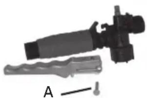
DISASSEMBLING AND REPAIRING THE SHUT OFF VALVE
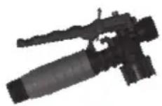
Figure 1
natural_image
Mechanical device with a lever and labeled component A (no text or symbols on the device itself)Figure 2

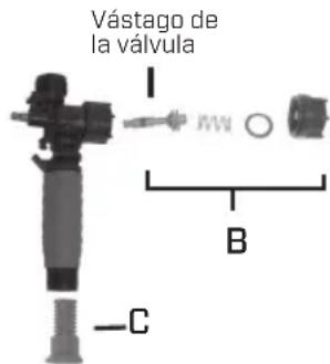
text_image
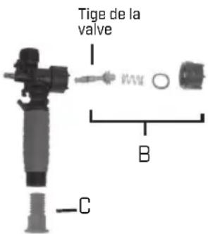
Valve Stem I B CFigure 3
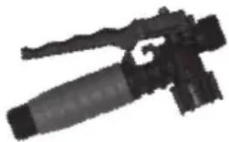
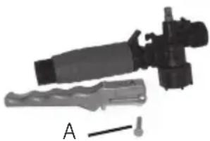
1) Assembled shut-off valve (Figure 1).
2) Remove the retaining pin [A] (Figure 2) place the notched end of the retaining pin on a hard surface and push down. Remove the retaining pin and slide the handle off the valve.
3) Remove the retaining nut (o-ring attached), spring, and valve stem (B) (Figure 3). Replace worn parts. Lubricate the O-rings and reassemble by reversing the steps above. Place the handle groove in the slotted area of the valve stem and make sure the locking clip is positioned in the neutral position (see "Helpful Spraying Information" section). Insert the retaining pin. Push down on the handle a few times to distribute the lubricant evenly. Check filter (C) in end of shut-off valve for debris. Remove filter and flush with water to clean out.
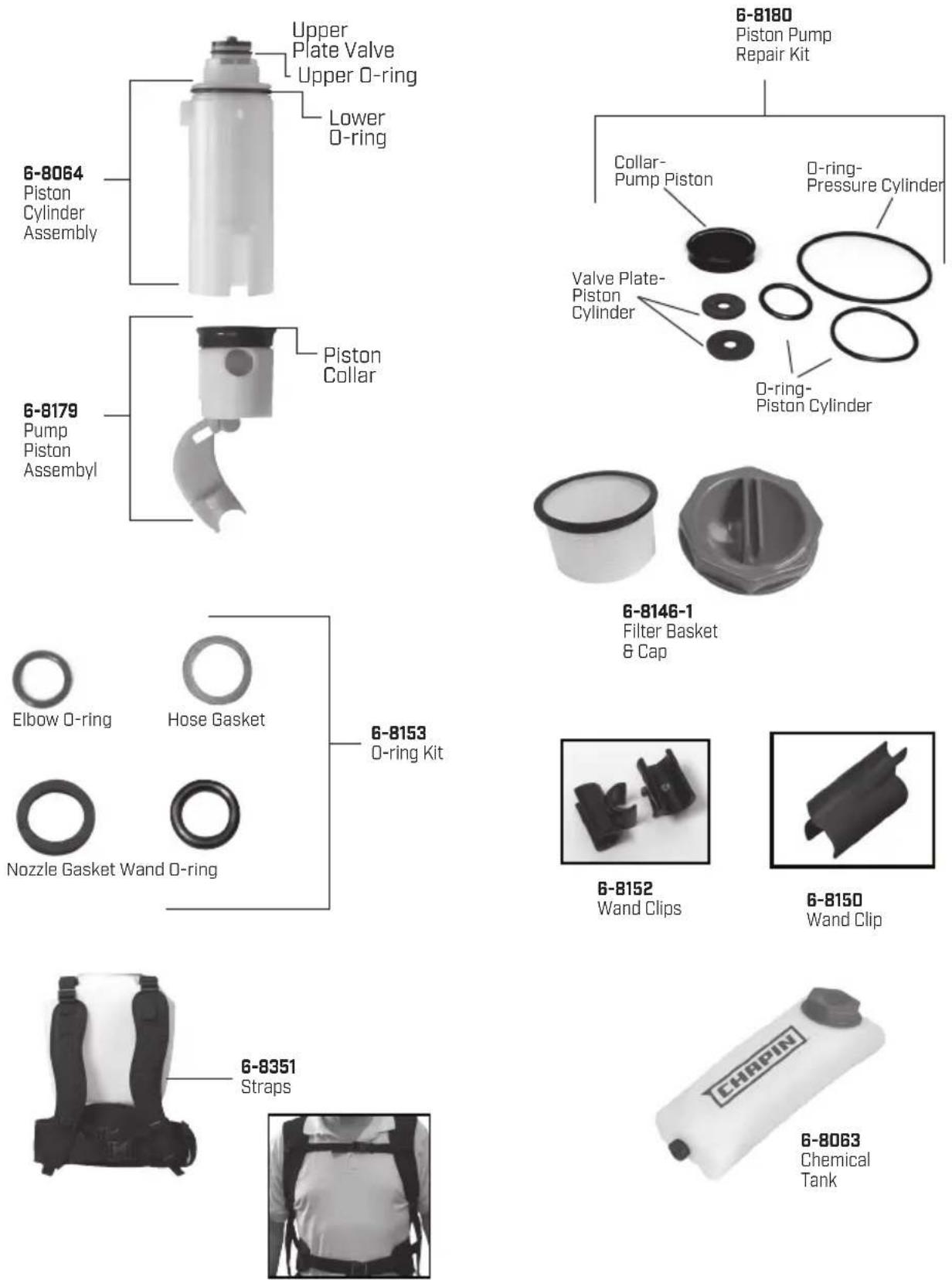
REPLACEMENT PARTS ORDER INFORMATION
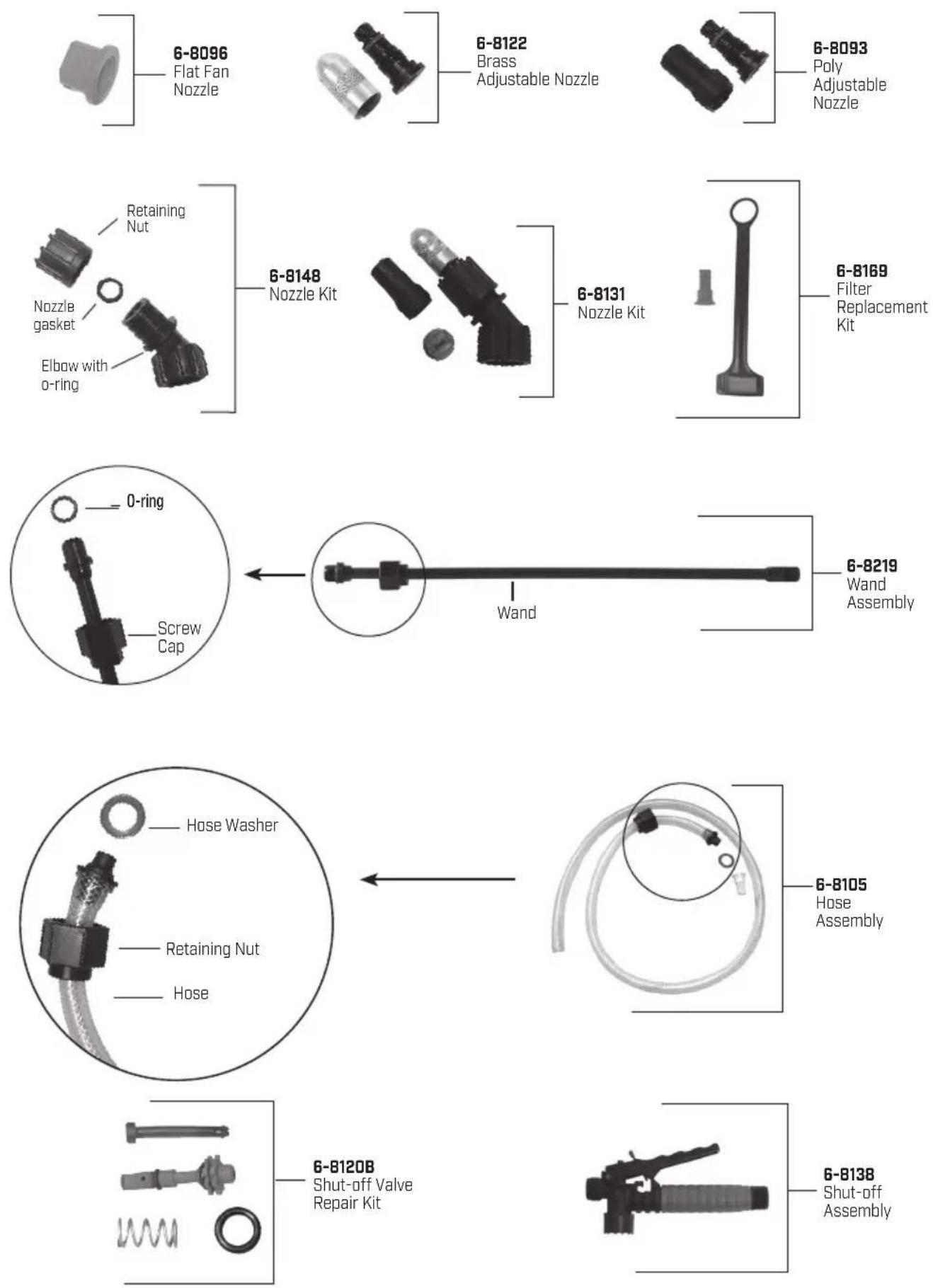
REPLACEMENT PARTS ORDER INFORMATION
Congratulations!
You have just purchased a quality Chapin product.
Register Your Sprayer Online@ www.chapinmfg.com/warranty.asp
Chapin International, Inc
MIXES ON EXIT™
Failure to do so may result in damage to property and/or person.

MIXES™
ON EXIT
text_image
IXES™ EXIT CHAPINnatural_image
Close-up of a mechanical component with bolts and a curved handle (no visible text or symbols)natural_image
Close-up of a mechanical assembly with bolts and wires (no visible text or symbols)natural_image
Close-up of a mechanical component with bolts and a curved rod (no visible text or symbols)natural_image
Close-up of a white spray gun with a black handle and white spray bottle (no text or symbols visible)Ensamblaje completo
natural_image
Close-up of a mechanical component with a cylindrical rod inserted into a hexagonal base (no visible text or symbols)Or
text_image
SUJETADOR PARA VARILLAnatural_image
Close-up of a mechanical component with a textured surface and a curved handle (no visible text or symbols)natural_image
Close-up of a mechanical component with textured surface and pointed tip (no visible text or symbols)natural_image
Hand holding a white cylindrical device with a black label 'Z' and 'O' on its side, next to a small base (no readable text or symbols)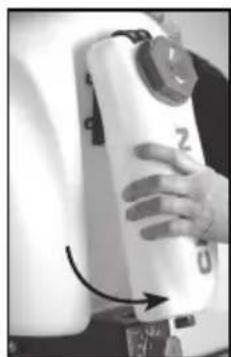
natural_image
Close-up of a hand holding a white cylindrical device with a black label 'Z' and arrow pointing to it (no readable text or symbols beyond the label)Figure 2 Figure 1
natural_image
Close-up of a mechanical valve assembly with a curved arrow indicating rotation (no text or symbols visible)Figura 1 Figura 2 Figura 3
natural_image
Close-up of hands holding a small circular object inside a vehicle's seat (no visible text or symbols)Figure 2
natural_image
Close-up of a hand holding a white cylindrical object with a black border (no visible text or symbols)Figure 4

natural_image
Close-up of a hand holding a white plastic tool next to a cylindrical container (no visible text or symbols)Figure 5
text_image
CollarínFigure 6
natural_image
Close-up of a gloved hand holding a small metallic object with an arrow pointing upward (no visible text or symbols)Figure 8
natural_image
Close-up of hands assembling or adjusting a mechanical component (no visible text or symbols)Figure 10
natural_image
Close-up of a hand holding a small white object with a dark ring, possibly a device or tool, against a blurred background (no visible text or symbols)Figure 11
text_image
Tapa protectora antipolvoFigure 12
natural_image
Close-up of a hand using a tool to cut or inspect a cylindrical object, no visible text or symbolsnatural_image
Close-up of a hand holding a small black object with a white cylindrical component (no visible text or symbols)Figura 2b
natural_image
Close-up of a medical device with a black tool inserted, no visible text or symbolsFigura 3a Figura 3b
text_image
Ranura del tanque Ranura de la bombaFigura 4
text_image
Ranura del tanque lengüe- ta de la estructura Ranura de la bombaFigura 5
text_image
engüeta de la estructura Abrazadera Pernos PernosaFigure 6
PARA DESARMAR Y REPARAR LA VÁLVULA DE CIERRE
natural_image
Black-and-white photo of a firearm with a long handle and barrel (no visible text or symbols)Figura 1
natural_image
Mechanical assembly with a cylindrical component and a tool, labeled A (no text or symbols on the main subject)Figura 2
text_image
Vástago de la válvula I B CFigura 3
Failure to do so may result in damage to property and/or person.

MIXES™
ON EXIT

natural_image
Exterior view of a CHAPIN spray sprayer (no text or symbols on the device itself)
Veuillez con sulter le site Web
natural_image
Close-up of a mechanical clamp or bracket with metallic fittings (no visible text or symbols)natural_image
Close-up of a mechanical assembly with bolts and tubing (no visible text or symbols)natural_image
Close-up of a mechanical pipe fitting with bolts and a black cable (no visible text or symbols)Figure 5 Droit
natural_image
Close-up of a white spray gun with a black handle and white powder, no visible text or symbolsAssemblage terminé
INSTALLER LA BRETELLE
natural_image
Close-up of a mechanical component with a cylindrical rod inserted into a hexagonal base (no visible text or symbols)Ou
text_image
PINCE DU TUBESYSTÈME DE FILTRAGE À 3 ÉTAPES
natural_image
Close-up of a mechanical component with a textured surface and a small protrusion (no visible text or symbols)natural_image
Close-up of a black mechanical component with a mesh grille (no visible text or symbols)natural_image
Hand holding a white cylindrical device with a black cap and upward arrow, no visible text or symbols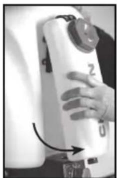
natural_image
Close-up of a hand holding a white cylindrical device with a black label 'Z' and arrow pointing to it (no readable text or symbols)Figure 2 Figure 1
UTILISATION DE BASE DES MÉLANGES SUR UN RÉGLAGE EXIT™
natural_image
Close-up of a mechanical valve assembly with a curved arrow indicating rotation (no text or symbols visible)Figure 1 Figure 2 Figure 3
natural_image
Close-up of hands holding a small mechanical component, possibly a tool or device (no visible text or symbols)Figure 2
text_image
Écrou de retenueFigure 3

natural_image
Close-up of a hand holding a white cylindrical object, possibly a pump or pipe fitting (no visible text or symbols)Figure 4
natural_image
Close-up of a hand holding a white plastic tool with a cylindrical component (no visible text or symbols)Figure 5
text_image
CollierFigure 6
natural_image
Close-up of a gloved hand holding a small mechanical component, with no visible text or symbols.Figure 8
natural_image
Close-up of hands using a tool to adjust or install a small object (no visible text or symbols)Figure 10
natural_image
Close-up of a hand adjusting a white cylindrical object with a dark ring (no visible text or symbols)Figure 11
text_image
Capuchon de protection anti- poussières.Figure 12
natural_image
Close-up of a hand using a tool to lift a white cylindrical object, possibly a pump or filter (no visible text or symbols)Figure 2a
natural_image
Close-up of hands holding a black cable or wire, no visible text or symbolsFigure 2b
natural_image
Close-up of a medical procedure with a black tool partially visible (no text or symbols)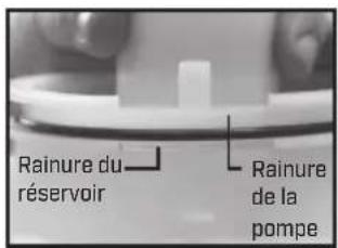
natural_image
Black-and-white photo of a firearm with lever and barrel (no visible text or symbols)Figure 1
natural_image
Mechanical assembly with a cylindrical component and a flanged base, labeled A (no text or symbols on the main subject)Figure 2
text_image
Tige de la valve B CFigure 3
natural_image
Two plastic pipe fittings: a white cylindrical component with black rim and a gray hexagonal cover (no text or symbols visible)natural_image
Close-up of a black plastic mechanical component (no text or symbols visible)6-8150
Pinces du tube
natural_image
Black and white photo of a person wearing a full-body seatbelt (no text or symbols visible)6-8351
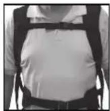
Sangles
natural_image
Person wearing a vest and belt, no visible text or symbols