6400 - Agricultural accessory Chapin - Free user manual and instructions
Find the device manual for free 6400 Chapin in PDF.

User questions about 6400 Chapin
0 question about this device. Answer the ones you know or ask your own.
Ask a new question about this device
Download the instructions for your Agricultural accessory in PDF format for free! Find your manual 6400 - Chapin and take your electronic device back in hand. On this page are published all the documents necessary for the use of your device. 6400 by Chapin.
USER MANUAL 6400 Chapin
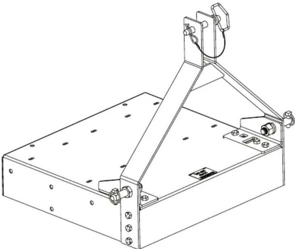
Failure to do so may result in damage to property and/or person.
natural_image
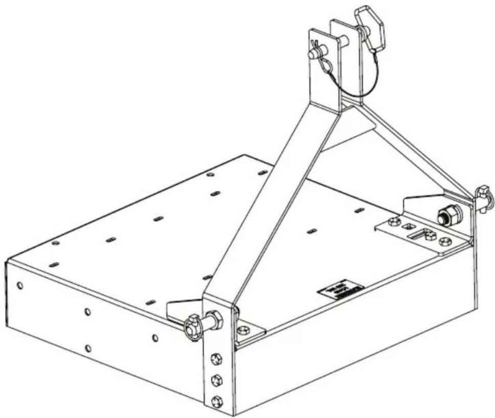
Technical line drawing of a mechanical support structure with mounting holes and a vertical frame (no text or symbols)Model 6400
CONGRATULATIONS!
YOU HAVE JUST PURCHASED A QUALITY CHAPIN PRODUCT.
BEFORE RETURNING THIS PRODUCT FOR ANY REASON, PLEASE CALL:
1-800-950-4458
When calling, please have the following information available: Sales receipt & model number. This number connects you directly with the manufacturer of this product. Our Technical Support Team will be happy to help you with any assembly, troubleshooting and replacement information you may need.
Hardware Kit (Not Actual Size)
natural_image
Simple line drawing of a circular mechanical part with a central vertical bar (no text or symbols)H-3
natural_image
Technical line drawing of a bolt and nut assembly (no text or symbols)H-4
Adjustable pin Clavija ajustable Goupille réglable
Not Shown: Bonus hose/rope carrier with mount bracket.
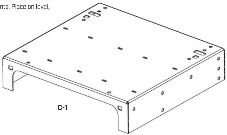
Hitch plate (C-1) is to be used as the base for attaching other components. Place on level, flat surface for assembly
text_image
nts. Place on level, C-12
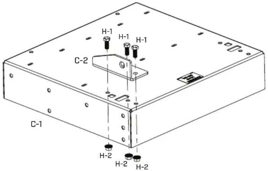
LEFT CORNER BRACKET ASSEMBLY
Facing the side of hitch plate [C-1] with the two multi-holed corners, attach left corner bracket [C-2] to the left side using bolts [H-1] and locknut [H-2] from 303352 parts bag.
text_image
H-1 H-1 H-1 C-2 C-1 H-2 H-2 H-22.1
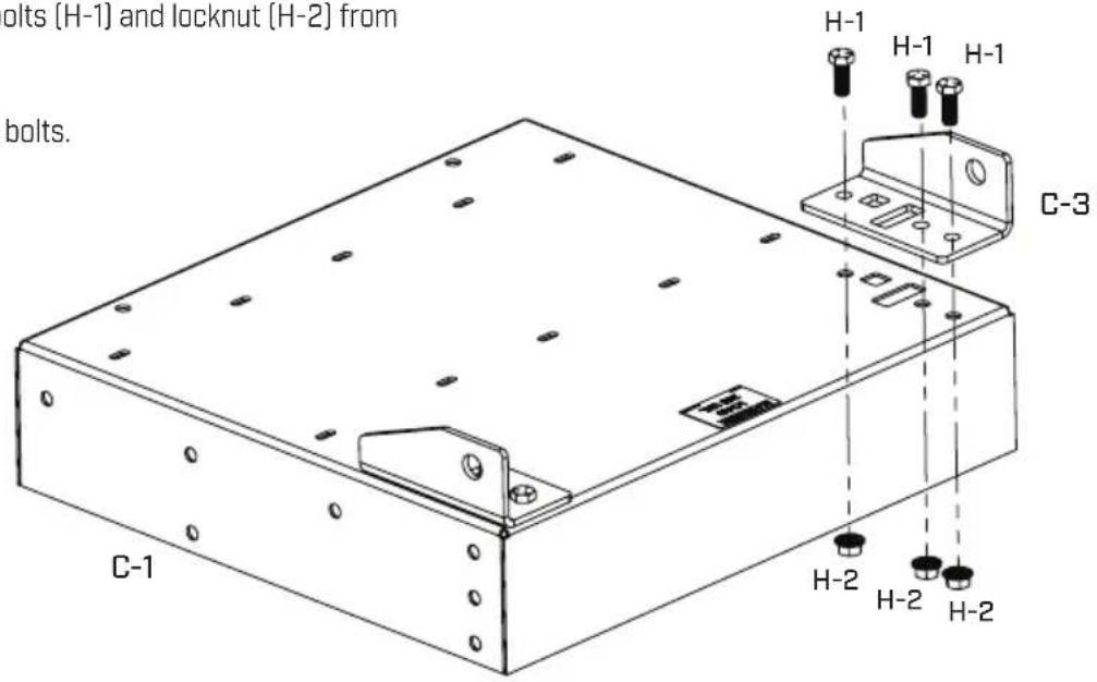
Facing the side of hitch plate (C-1) with the two multi-holed corners, attach right corner bracket (C-3) to the right side using bolts (H-1) and locknut (H-2) from 303352 parts bag.
Tighten the nuts and bolts.
text_image
bolts (H-1) and locknut (H-2) from bolts. C-1 H-1 H-1 H-1 C-3 H-2 H-2 H-23
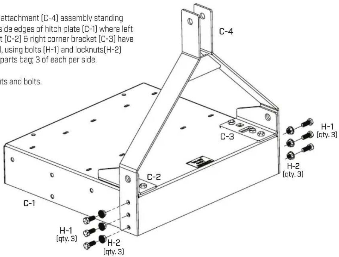
MOUNT ASSEMBLY
Attach mount attachment [C-4] assembly standing upright to outside edges of hitch plate [C-1] where left corner bracket [C-2] & right corner bracket [C-3] have been attached, using bolts [H-1] and locknuts[H-2] from 303352 parts bag; 3 of each per side.
Tighten the nuts and bolts.
text_image
attachment [C-4] assembly standing side edges of hitch plate [C-1] where left t [C-2] & right corner bracket [C-3] have , using bolts [H-1] and locknuts[H-2] parts bag; 3 of each per side. ts and bolts. C-4 C-3 C-2 C-1 H-1 [qty. 3] H-2 [qty. 3] H-1 [qty. 3] H-2 [qty. 3]3.1
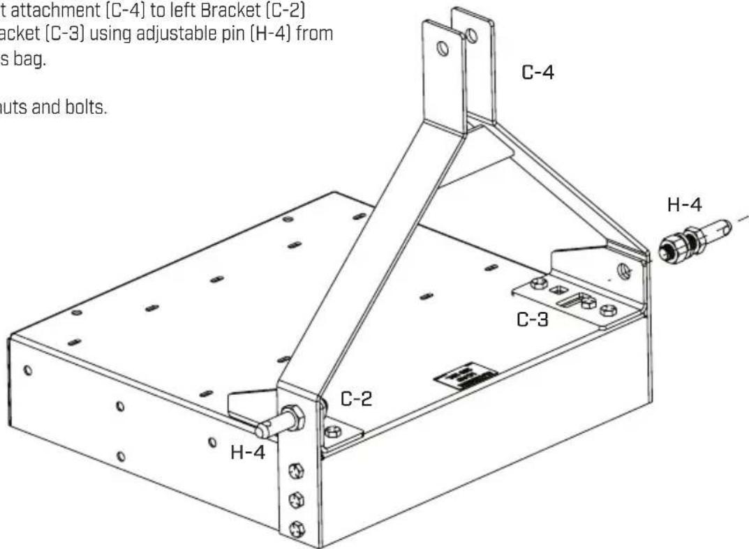
Attach Mount attachment [C-4] to left Bracket [C-2] and Right Bracket [C-3] using adjustable pin [H-4] from 303352 parts bag.
Tighten the nuts and bolts.
text_image
t attachment [C-4] to left Bracket [C-2] acket [C-3] using adjustable pin (H-4) from s bag. outs and bolts. C-4 C-3 H-4 C-2 H-44
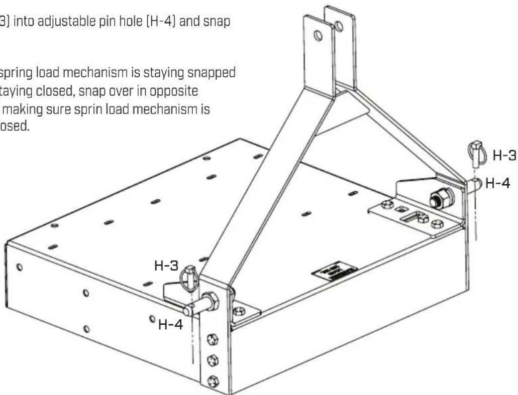
LINCH PIN ASSEMBLY
Insert linch pin (H-3) into adjustable pin hole (H-4) and snap closed.
NOTE: Make sure spring load mechanism is staying snapped closed; if it is not staying closed, snap over in opposite direction while still making sure spring load mechanism is staying snapped closed.
text_image
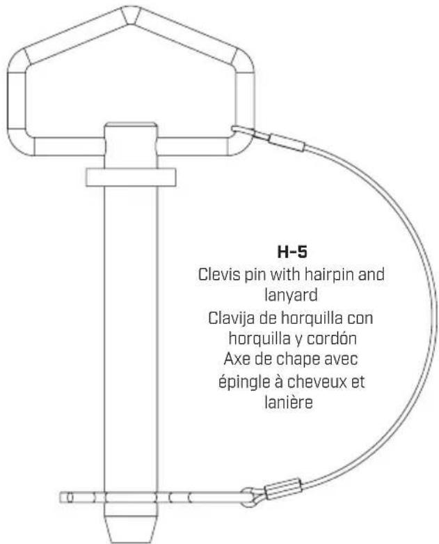
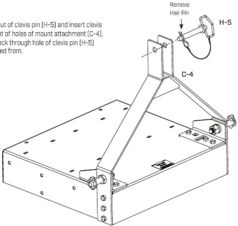
(3) into adjustable pin hole (H-4) and snap spring load mechanism is staying snapped staying closed, snap over in opposite making sure spring load mechanism is posed. H-3 H-4 H-4Remove hair pin out of clevis pin (H-5) and insert clevis pin through top set of holes of mount attachment (C-4). reinsert hairpin back through hole of clevis pin (H-5) where was removed from.
text_image
ut of clevis pin (H-5) and insert clevis set of holes of mount attachment (C-4). ack through hole of clevis pin (H-5) ed from. Remove Hair Pin H-5 C-4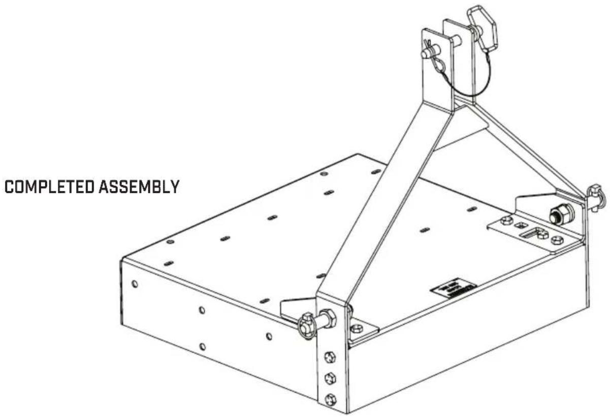
text_image
COMPLETED ASSEMBLYCARRY ALL
[Transporta Materiales]
MANUAL DE USO
Y CUIDADO
ADVERTENCIA
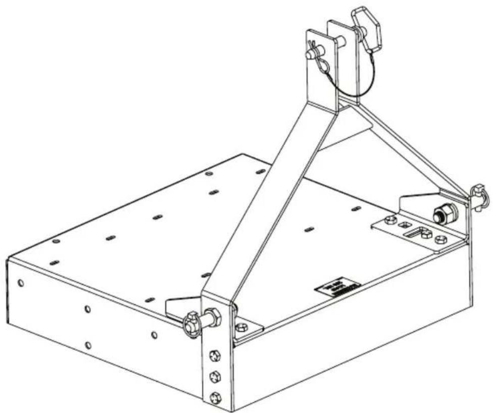
Failure to do so may result in damage to property and/or person.
natural_image
Technical line drawing of a mechanical support structure with mounting holes and a vertical frame (no text or symbols)Modelo 6400
¡FELICITACIONES!
ACABA DE COMPRAR UN PRODUCTO DE CALIDAD CHAPIN.
REGISTRE SU ESPARCIDOR EN LÍNEA EN WWW.CHAPINMFG.COM/WARRANTY.ASP
VISIT US ON THE INTERNET: WWW.CHAPINMFG.COM
text_image
H-1 H-1 H-1 C-2 C-1 H-2 H-2 H-22.1
natural_image
Technical line drawing of a mechanical assembly with mounting flanges and a support frame (no text or symbols)Chapin International, Inc
CARRY ALL
Failure to do so may result in damage to property and/or person.
natural_image
Technical line drawing of a mechanical support structure with mounting holes and a vertical frame (no text or symbols)Modèle 6400
Félicitations!
VOUS VENEZ D'ACHETER UN PRODUIT DE QUALITÉ CHAPIN.
ENREGISTREZ VOTRE ÉPANDEUR EN LIGNE @ WWW.CHAPINMFG.COM/WARRANTY.ASP
VISIT US ON THE INTERNET: WWW.CHAPINMFG.COM
AVANT DE RETOURNER CE PRODUIT POUR QUELQUE RAISON QUE CE SOIT, VEUILLEZ APPELER :