
SS-21820 - Fan Sogo - Free user manual and instructions
Find the device manual for free SS-21820 Sogo in PDF.

| Product type | Ceiling fan |
| Brand | Sogo |
| Model | SS-21820 |
| Power supply | 220-240V~ 50-60Hz |
| Power | 85W |
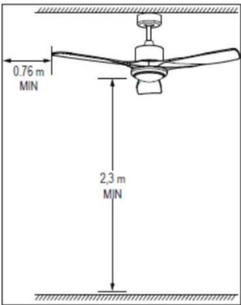
| Minimum installation height | 2.3 m from floor |
| Minimum distance from wall/obstacle | 0.76 m |
| Number of speeds | 3 (High, Medium, Low) |
| Lighting | Integrated LED with 3 color temperatures (3000K, 4000K, 6000K) |
| Reversible function | Yes (clockwise in winter) |
| Timer | Yes (1h, 2h, 4h, 8h) |
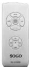
| Remote control | Included |
| Usage | Indoor only |
| Installation | By a certified electrician |
| Maintenance | Soft dry or slightly damp cloth |
| Safety | Disconnect power before servicing |
| Reparability | Repairs by a certified electrician |
| Included accessories | Remote control, balancing kit, screws and anchors |
Frequently Asked Questions - SS-21820 Sogo
User questions about SS-21820 Sogo
0 question about this device. Answer the ones you know or ask your own.
Ask a new question about this device
Download the instructions for your Fan in PDF format for free! Find your manual SS-21820 - Sogo and take your electronic device back in hand. On this page are published all the documents necessary for the use of your device. SS-21820 by Sogo.
USER MANUAL SS-21820 Sogo
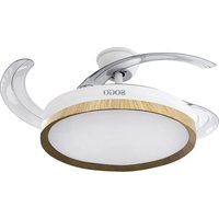
natural_image
Modern office ceiling fan with four wooden blades and a central hub (no text or symbols visible)
VENTILADOR DE TECHO DE 52" CEILING FAN 52"
VENTILATEUR DE PLAFOND 52"
VENTILADOR DE TETO 52"
DECKENVENTILATOR 52"
VENTILATORE DA SOFFITTO 52"
Caution: please read and preserve these important instructions
INSTRUCCIONES DE USO
IMPORTANT SAFETY INSTRUCTIONS
- This instruction manual can also be downloaded from our web page www.sogo.es
- WARNING: When using electrical appliance, basic safety precautions should always be followed to reduce the risk of fire, electrical shock and personal injury.
- Use this fan only as described in this manual. Other use not recommended may cause fire, electric shock or injury to persons. This will also void your warranty.
- Connect to a main power supplier of 220-240V\~ 50-60 Hz only.
- Indoor use only.
- Under our warranty terms, this ceiling fan must be correctly installed by a licensed electrician. Improperly installed ceiling fans can be dangerous and expensive to repair, it will also void your warranty.
- Before installing the fan, make sure you have turned off the main electricity supply. Do not turn it back on until the fan is fully installed and ready to use.
- To protect against electric shock: do not immerse unit or cord in water or spray with liquids.
- This appliance can be used by children aged from 8 years and above and persons with reduced physical, sensory or mental capabilities or lack of experience and knowledge if they have been given supervision or instruction concerning use of the appliance in a safe way and understand
the hazards involved.
• Children shall not play with the appliance.
- Cleaning and user maintenance shall not be made by children without supervision.
- Turn the fan OFF when not in use and before disassembling or cleaning. Fully assemble the fan before switching on again.
- The use of attachments not recommended by the manufacturer may be hazardous.
- Do not operate if the fan housing is damaged.
- If the cord is damaged, it must be replaced by the manufacturer, its service agent or similarly qualified persons in order to avoid a hazard.
- If the fan is not working properly, contact a qualified technician for examination and repair. Never attempt to dismantle the fan yourself.
WARNING: To reduce the risk of electrical shock and fire, do not use this fan with any solid-state fan speed control device, or rheostat. Do not separate the reverse switch until the fan has come to a complete stop.
Do not insert anything into the fan blades while they are rotating.
WARNING: To reduce the risk of personal injury, do not bend the blade brackets (also referred to as “flanges”) during assembly or after installation. Do not insert objects in the path of the blades.
To avoid personal injury or damage to the fan and other items, be cautious when working around or cleaning the fan. Do not use water or
detergent when cleaning the fan or fan blades. A dry dust cloth or lightly dampened cloth will be suitable for most cleaning.
NOTE: The important safety precautions and instructions appearing in the manual are not meant to cover all possible conditions and situations that may occur. It must be understood that common sense and caution are necessary factors in the installation and operation of this fan.
WARNING:
Equipment must be installed at the height of at least 2,3 meters from the floor (2,3 meters means from the floor to the bottom of the fan), 0.76m from wall or obstruction. Since the installation of the equipment sets, the power of the network must be done through flexible cable plug or by pole switch with contact opening distance not less than 3 mm.
PRODUCT DESCRIPTION
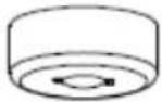 |  | 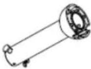 |
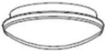
| Upper canopy Support plate support rod | ||
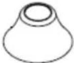 | 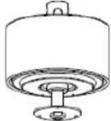 |  |
| Lower canopy Motor LED light kit | ||
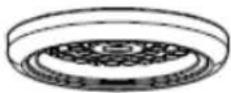
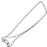 |  | 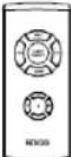 |
| Blades Lamp shade Remote control | ||
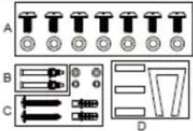 | A: Screws and washers for securing the blades (fixed on the motor housing).B: Screws for concrete ceilingC: Screws and washers for wood joist ceilingD: Blance kit | |
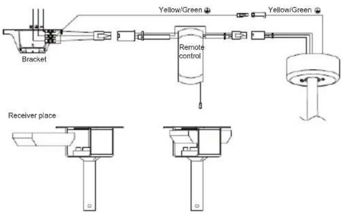
REMOTE CONTROL CNNECTION
WARNING: To avoid personal injury or damage, be sure to turn off the power to the main fuse box before wiring.
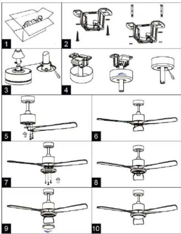
ASSEMBLING
Make sure you have all the components before beginning installation. To prevent damage, attach the motor to the support rod on a soft surface or use the polystyrene contained in the package.
- Open the carton box and take out the fan (fig. 1).
-
Assemble the support plate on the ceiling using two or more screw anchors and appropriate washers. Attention: the provided screw are for wood joist and concrete ceiling. (fig. 2).
-
Insert the support rod through the upper cap and lower cap.
-
Insert the electric cables coming out from the motor through the support rod and connect them to the screw terminal placed on the top of support rod.
-
Fix the support rod to the motor using the pin and pin's nut. (fig. 3)
-
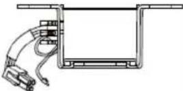
Hang the fan on the hook on the support plate and connect the electrical cable coming from the ceiling to the screw terminal placed on the top of support rod, make sure the receiver must be insert into support plate (see Remote control connection).
-
Slide upwards the upper cap and fix it with the screw. (fig. 4)
-
Slide downwards the lower cap; it must be supported by the motor. Fix it with the screw. (fig. 4)
-
Center the slots on the blades with the heads of the blades fixing screws and slide the blades so that the head of the screws are positioned at the end of slot. (fig. 5)
-
Tighten the screw. (fig. 6)
-
Remove the screws from connect plate of the motor, please organize all the wires carefully into connect plate. Assemble and align the holes on the back of LED light to the three screws on the connect plate of motor. (fig. 7)
-
Then tighten the three screws on the LED plate, connect the connector together with the motor wire, please make sure the light kit can't be moved after tighten the screws. (fig. 8)
-
Place the lamp shade on the fan.(fig. 9)
INSTRUCTIONS FOR USE
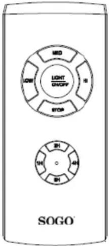
The ceiling fan is provided with a remote control. To turn on the ceiling fan select the desired speed and the fan will turn on with the selected speed: HI High speed
MED Medium speed
LOW Low speed
STOP Turn off the ceiling fan
LIGHT: To turn On the light push the button "LIGHT ON/OFF".
There are three levels of light intensity. When you press it once the light will switch on at intensity level 1 (3000K), pressing it again will change it to intensity level 2 (4000K), press it for the third time for maximum light intensity (6000K) and press it once more to switch off the light. Light can also be turned on while the fan is off.
TIMER: Off timer can be set using the four option on the remote control 1h, 2h, 4h and 8h. If the timer has been set before, pressing any of the timer button again will reset the timer from the beginning.
REVERSIBLE BLADES MOVEMENT OPERATION:
This fan has a reversible function for the fan blades movement for use in the winter season. The normal fan function direction is always in anti clockwise direction where as the reversible function is in clockwise direction.
The reversible function can be switched ON by moving the manual control switch located next to the motor housing. The initial factory setting of this manual switch is for use of the fan in summer time. When you need to use it during Winter, just change the switch direction manually and the fan will be in reversible function mode.
Note: Using the reversible function of the fan not only makes your room warmer, but also helps you to reduce the energy use and lowering the electricity bill. PIs do take extra care for your safety when you use the ladder to change the position of the switch manually.
CLEANING AND MAINTAINENCE
Cleaning:
- Before cleaning, turn the unit off, cut off the power supply from electrical outlet and wait for the unit to cool down.
- To clean the unit, use a soft cloth to wipe off any dust.
- Do not try to open the unit without a licensed electrician. Improperly installed the unit can be dangerous.
- Clean the unit at least once a year.
Maintenance:
- Have your product repaired by a licensed electrician
- This electric product is in accordance with the relevant safety requirements. Repairs should only be carried out by licensed electricians using original spare parts, otherwise this may result in considerable danger to the user.
- Please contact the store which you bought the product for after sale services if any.
TECHNICAL INFORMATION
Model: SS-21820
Voltage / Frequency: 220-240V\~ 50-60Hz
Output Power: 85W
CONSIGNES DE SÉCURITÉ IMPORTANTES
MODE D'EMPLOI
FONCTIONNEMENT RÉVERSIBLE DE MOUVEMENT DE LA LAME :
INSTRUÇÕES DE USO
GEBRAUCHSANWEISUNG
Directive 2009/125/EC
Directive 2009/125/EC
| Description Symbol Value Unit | |||
| Alimentation / Fonte de energia | 220-240V~ 50-60Hz | ||
| Puissance / Potência | 85W | ||
| Classe / Class | I | ||
| Débit du ventilateur / Caudal do ventilador | F | 158.82 | m3/min |
| Puissance d'entrée du ventilateur / Entrada de energia do ventilador | P | 67.1 | W |
| Valeur du service / Valor do serviço | SV | 2.37 | (m3/min)/W |
| Consommation électrique en veille / Consumo de energia em espera P SB | 0.23 | W | |
| Hors consommation d'énergie / Consumo de energia desligada | P off | 0 | W |
| Niveau de puissance acoustique du ventilateur / Nível de potência sonora do ventilador | L WA | 47.1 | dB(A) |
| Vitesse de l'air / Velocidade do ar | c meters/sec | 2.37 | |
| Consommation d'électricité utilisée / Consumo de eletricidade em uso | Q | 21.7 | kWh/a |
| Norme de mesure pour voler du service /Padrão de medição para sair do serviço | IEC 60879:1986 /corr.1992) | ||
ITA / ALE
Directive 2009/125/EC
| Description Symbol Value Unit | |||
| Alimentazione / Stromversorgung 220-240V~ 50-60Hz | |||
| Potere / Potenz | 85W | ||
| Clase / Klasse I | |||
| Portata del ventilatore / Lüfterdurchfluss F m3/min | 158.82 | ||
| Potenza assorbita dal ventilatore / Lüfterleistungseingang P W | 67.1 | ||
| Valore del servicio / Servicewert SV (m3/min)/W | 2.37 | ||
| Consumo energético in standby / Standby-Stromverbrauch P | SB | 0.23 | W |
| Consumo energetico spento / Stromverbrauch ausschalten P | off | 0 | W |
| Livello di potenza sonora del ventilatore / Lüfter-Schallleistungspegel | L WA | 47.1 | dB(A) |
| Velocità dell'aria / Luftgeschwindigkeit | c | 2.37 | meters/sec |
| Consumo di elettricità in uso / Stromverbrauch im Einsatz | Q | 21.7 | kWh/a |
| Standard di misura per volare dal servicio / Messstandard, um vom Dienst zu fliegen | IEC 60879:1986 /corr.1992) | ||
DECLARATION OF CONFORMITY
This device complies with Low Voltage Directive 2014/35/EC, Electromagnetic Compatibility Directive 2014/30/EU, Directive 2015/863/EU on the restriction of the use of certain hazardous substances in electrical and electronic equipment and Directive 2009/125/EC on the eco-design requirements applicable to energy-related products.
DÉCLARATION DE CONFORMITÉ
This symbol means that in case you wish to dispose of the product once its working life has ended, take it to an authorised waste agent for the selective collection of waste electrical and electronic equipment (WEEE).

Imported by:
Sanysan Appliances S.L, NIF: B98753056, C/ Barcas 2, 2 46002 Valencia, Spain Product made in P.R.C. – Designed by SOGO based on the European Quality Standards Customer Service: www.sogosat.com / sogosat@sogosat.com / 0034 902 222 161

- INSTRUCCIONES DE USO
- IMPORTANT SAFETY INSTRUCTIONS
- WARNING:
- PRODUCT DESCRIPTION
- REMOTE CONTROL CNNECTION
- ASSEMBLING
- INSTRUCTIONS FOR USE
- REVERSIBLE BLADES MOVEMENT OPERATION:
- CLEANING AND MAINTAINENCE
- Cleaning:
- Maintenance:
- TECHNICAL INFORMATION
- CONSIGNES DE SÉCURITÉ IMPORTANTES
- MODE D'EMPLOI
- FONCTIONNEMENT RÉVERSIBLE DE MOUVEMENT DE LA LAME :
- INSTRUÇÕES DE USO
- GEBRAUCHSANWEISUNG
- ITA / ALE
- DECLARATION OF CONFORMITY
- DÉCLARATION DE CONFORMITÉ
- Imported by:
Brand : Sogo
Model : SS-21820
Category : Fan