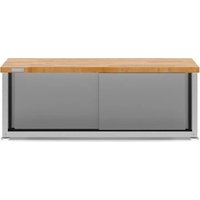
GABK362PSS - Tool cabinet accessory Gladiator - Free user manual and instructions
Find the device manual for free GABK362PSS Gladiator in PDF.

User questions about GABK362PSS Gladiator
0 question about this device. Answer the ones you know or ask your own.
Ask a new question about this device
Download the instructions for your Tool cabinet accessory in PDF format for free! Find your manual GABK362PSS - Gladiator and take your electronic device back in hand. On this page are published all the documents necessary for the use of your device. GABK362PSS by Gladiator.
USER MANUAL GABK362PSS Gladiator
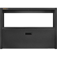
Installation Instructions
ENSEMBLE DE TRINGLES EN ACIER POUR GRANDE ET TRÈS GRANDE ARMOIRE À OUTILS
MOUNTING BRACKET SAFETY .....2
INSTALLATION INSTRUCTIONS......2
Tools and Parts 2
Unpack Brackets ......2
Assemble Brackets....2
Attach Mounting Brackets....3
Mount the Cabinet to GearWall®
Panels or GearTrack ^® Channel .....4
WARRANTY......4
SÉCURITÉ DE LA TRINGLE DE MONTAGE ....5
INSTRUCTIONS D'INSTALLATION .... 5
MOUNTING BRACKET SAFETY
Your safety and the safety of others are very important.
We have provided many important safety messages in this manual and on your appliance. Always read and obey all safety messages.

This is the safety alert symbol.
This symbol alerts you to potential hazards that can kill or hurt you and others.
All safety messages will follow the safety alert symbol and either the word "DANGER" or "WARNING."
These words mean:
DANGER
You can be killed or seriously injured if you don't immediately follow instructions.
WARNING
You can be killed or seriously injured if you don't follow instructions.
All safety messages will tell you what the potential hazard is, tell you how to reduce the chance of injury, and tell you what can happen if the instructions are not followed.
INSTALLATION INSTRUCTIONS
Tools and Parts
Gather the required tools and parts before starting installation.
Tools Needed:
■1/2" Wrench
Parts Supplied:
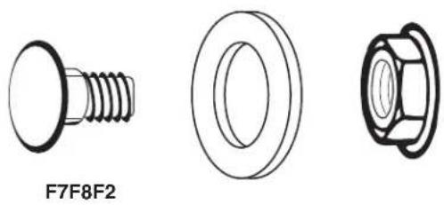
■ Mounting bracket sections (6)
■ Carriage-head bolt (9)
■ 5/16" Flange nut (9)
■ Washer (9)
Bracket Use Requirements
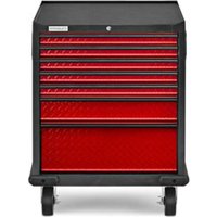
■Intended for use with Gladiator® Steel Large GearBox or Extra Large GearBox cabinets only. Please use the instructions specific to your cabinet.
■Intended to be used for mounting cabinets on Gladiator® GearWall® panels or GearTrack® channels.
■Brackets will support a cabinet with a maximum weight limit of 250 lbs (113.6 kg).
Unpack Brackets
- Verify contents. See "Parts Supplied."
- Dispose of/recycle all packaging materials.
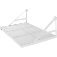
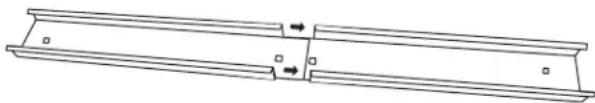
Assemble Brackets
Slide the end of one bracket section into the end of another section until the center holes are aligned.
natural_image
Pure technical line drawing of a mechanical component with no text or symbolsAttach Mounting Brackets
natural_image
Three technical drawings of a bolt and nut assembly (no text or symbols)F7. Carriage-head bolt (9) F2. 5/16" Flange nut (9)
F8. Washer (9)
Attach to Large GearBox
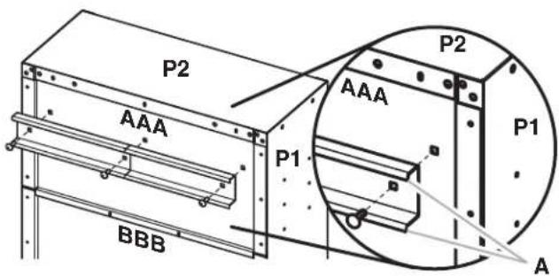
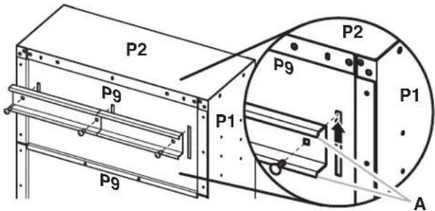
IMPORTANT: There are holes in back panels (AAA, CCC, and DDD) to attach the mounting brackets.
- With the mounting bracket rims pointing down, align the three bracket holes with the holes in the top back panel (AAA), as shown.
- Working from the back, insert carriage bolts (F7) through the bracket and into top back panel (AAA).
- Working from the cabinet interior, fasten each bolt with a washer (F8) and a flange nut (F2). Fully tighten the bolts.
text_image
P2 AAA P1 BBB P2 AAA P1 AA. Bracket rims pointing down
- Repeat Steps 1 and 2 to attach the center and bottom mounting brackets to the back of the cabinet.
NOTE: Hand tighten the nuts attaching the center and bottom brackets. These brackets will need to be adjusted to mount the cabinet on the wall.
natural_image
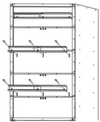
Technical line drawing of a multi-level industrial storage unit with no visible text or symbolsAttach to Extra Large GearBox
- With the mounting bracket rims pointing down, align the three bracket holes with the slots in the top back panel (P9), as shown.
- Working from the back, insert carriage bolts (F7) through the bracket and into top back panel (P9).
- Working from the cabinet interior, fasten each bolt with a washer (F8) and a flange nut (F2).
NOTE: For the top bracket only, slide the bolts to the top of the slot before fastening.
- Fully tighten the bolts.
text_image
P2 P9 P1 P9 P2 P9 P1 AA. Bracket rims pointing down
- Repeat Steps 1 through 3 to attach the center bracket to the third back panel and the bottom mounting bracket to the fifth back panel as shown.
NOTE: Hand tighten the nuts attaching the center and bottom brackets. These brackets will need to be adjusted to mount the cabinet on the wall.

natural_image
Technical line drawing of a multi-level metal shelving unit with no visible text or symbolsMount the Cabinet to GearWall® Panels or GearTrack® Channel
IMPORTANT:
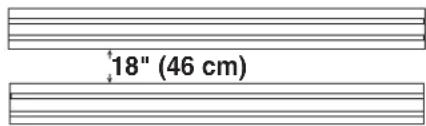
■Be sure the GearWall® panels or GearTrack® channels are installed with mounting screws in every slot and at every stud location with a maximum of 24" (60.96 cm) horizontally between screws.
■If GearTrack® channels will be used to support the Gladiator® Large GearBox cabinet, you must use three channels installed 18" (45.72 cm) apart.
text_image
18" (46 cm)NOTE: The three nuts on the center and bottom mounting brackets must be loose enough to allow the brackets to move in the slots.
- Close the cabinet doors.
- Determine cabinet mounting location on GearWall® panels or GearTrack® channel.
WARNING
Excessive Weight Hazard
Use two or more people to move, assemble or install cabinet.
Failure to do so can result in back or other injury.
-
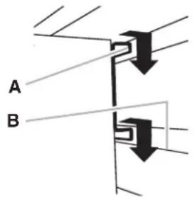
Using two or more people, engage the top bracket into the slots by lifting up, pushing toward the wall and lowering the bracket rims into the slots as shown.
-
Make sure the top bracket is fully engaged in the slots as shown.
text_image
A B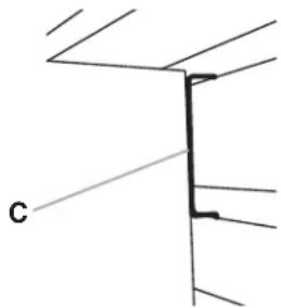
natural_image
Pure technical line drawing of a structural joint or bracket (no text or symbols)A. Bracket rim C. Mounting bracket fully engaged
- Open the cabinet doors.
- From inside the cabinet, grasp the bolts in the center bracket and adjust the bracket until it aligns with the slot in the GearWall® panels or GearTrack® channels.
- Push the cabinet toward the wall and lower the center mounting bracket into the slots.
- Make sure the center bracket is fully engaged in the slot as shown.
- Repeat for the bottom bracket.
- Using a 1/2" wrench, fully tighten the nuts attaching the center and bottom brackets.
WARRANTY
For warranty information:
In the U.S.A. call 1-866-342-4089 or visit our website at
www.gladiatorgarageworks.com
In Canada call 1-800-807-6777 or visit our website at
www.gladiatorgarageworks.ca
SÉCURITÉ DE LA TRINGLE DE MONTAGE
natural_image
Pure technical line drawing of a mechanical component with no text or symbolsnatural_image
Technical drawings of three mechanical components: a bolt, a washer, and a nut (no text or symbols)natural_image
Technical line drawing of a multi-level storage cabinet or rack unit with no visible text or symbolsnatural_image
Technical line drawing of a multi-level metal shelving unit with no visible text or symbolsnatural_image
Pure technical line drawing of a structural joint or bracket (no text or symbols)www.gladiatorgarageworks.com
www.gladiatorgarageworks.ca
SEGURIDAD DEL SOPORTE DE MONTAJE
natural_image
Pure technical line drawing of a mechanical component with no text or symbolsnatural_image
Technical drawings of three mechanical components: a bolt, a washer, and a nut (no text or symbols)F7 Perno de carruaje (9) F2 Tuerca de reborde de 5/16" (9)
F8 Arandela (9)
Cómo fijarlo al armario grande
natural_image
Technical line drawing of a multi-level storage or rack cabinet with no visible text or symbolsnatural_image
Technical line drawing of a multi-level metal shelving unit with no visible text or symbolstext_image
18" (46 cm)natural_image
Pure technical line drawing of a structural joint or bracket (no text or symbols)www.gladiatorgarageworks.com
www.gladiatorgarageworks.ca