GANA201BMS - Wall mount Gladiator - Free user manual and instructions
Find the device manual for free GANA201BMS Gladiator in PDF.

User questions about GANA201BMS Gladiator
0 question about this device. Answer the ones you know or ask your own.
Ask a new question about this device
Download the instructions for your Wall mount in PDF format for free! Find your manual GANA201BMS - Gladiator and take your electronic device back in hand. On this page are published all the documents necessary for the use of your device. GANA201BMS by Gladiator.
USER MANUAL GANA201BMS Gladiator
Assembly Instructions
SUPPORT FLEX
natural_image
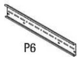
Technical line drawing of a long rectangular metal beam with internal cutouts and mounting holes (no text or symbols)TABLE OF CONTENTS/TABLE DES MATIÈRES/TABLA DE CONTENIDOS
BRACKET SAFETY 2
ASSEMBLY INSTRUCTIONS .....2
WARRANTY ....5
SÉCURITÉ DU SUPPORT ......6
INSTRUCTIONS D'ASSEMBLAGE...6
GARANTIE 9
SEGURIDAD DEL SOPORTE......10
INSTRUCCIONES DE
ENSAMBLAJE....10
GARANTÍA 13
BRACKET SAFETY
Your safety and the safety of others are very important.
We have provided many important safety messages in this manual and on your appliance. Always read and obey all safety messages.

This is the safety alert symbol.
This symbol alerts you to potential hazards that can kill or hurt you and others.
All safety messages will follow the safety alert symbol and either the word "DANGER" or "WARNING."
These words mean:
DANGER
You can be killed or seriously injured if you don't immediately follow instructions.
WARNING
You can be killed or seriously injured if you don't follow instructions.
All safety messages will tell you what the potential hazard is, tell you how to reduce the chance of injury, and tell you what can happen if the instructions are not followed.
ASSEMBLY INSTRUCTIONS
Tools and Parts
Gather the required tools and parts before starting installation.
Tools Needed:
■1 Socket Wrench with 10mm Socket
■4mm Hex Wrench
■Tape measure
Parts Supplied:
■Bracket(1)
■M6 hex flange nuts (4)
■M6 round head square neck bolts (4)
Bracket Use Requirements
■Intended for use on Gladiator® Flex Cabinet Systems' cabinets (sold separately).
Install the 30" Tall Cabinet
NOTE: Flex Brackets are sold individually and Gladiator® GearTrack® channels are sold separately.
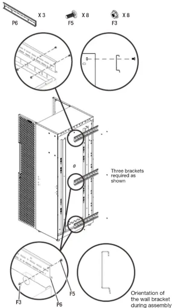
1. Install the brackets to the tall cabinet.
■ Attach the top bracket (P1) to the tall cabinet's back top with four M6 round head square neck bolts (F1) and four M6 flange nuts (F2).
■Attach the center and bottom brackets (P1) to the tall cabinet's back respectively with two M6 round head square neck bolts (F1) and two M6 flange nuts (F2).
WARNING
Excessive Weight Hazard
Use two or more people to move and install cabinet.
Failure to do so can result in back or other injury.
text_image
P6 X 3 F5 X 8 F3 X 8 Three brackets required as shown F3 P6 F5 Orientation of the wall bracket during assemblyPt: Bracket (3) F1: M6 round head square neck bolts (8)
F2: M6 hex flange nuts (8)
ASSEMBLY INSTRUCTIONS
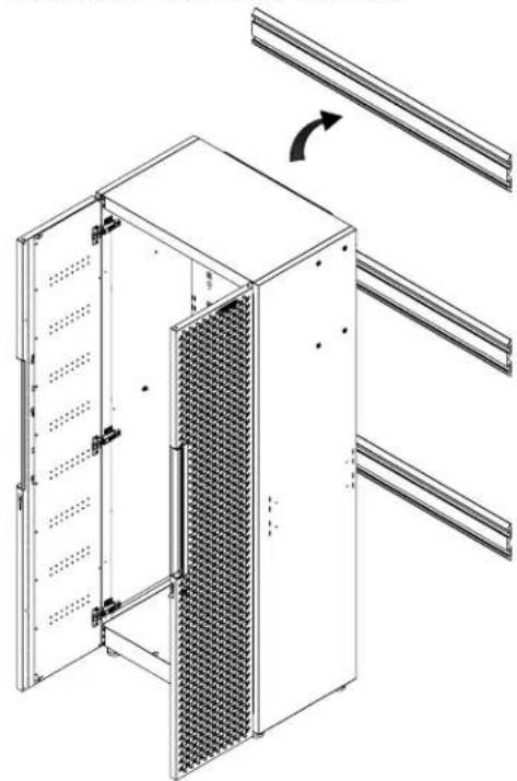
2. Hang the tall cabinet onto the GearTrack ^® channels
■Make sure all three brackets (P1) are fully engaged in the slots as shown.
NOTE: For installation of the Gladiator® GearTrack® channels, please refer to the manual instructions included with the Gladiator® GearTrack® channels.
natural_image
Technical line drawing of a server rack with ventilation grilles and mounting brackets (no text or symbols)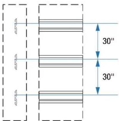
text_image
30" 30"The GearTrack ^® channels should be installed with the spacing as shown.
natural_image
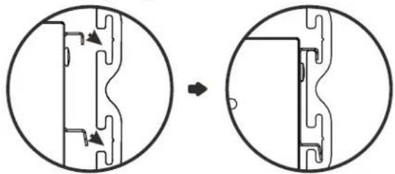
Diagram showing a mechanical component before and after transformation, with no visible text or symbols.Install the 24" Flex Wall Cabinet
NOTE: Flex Brackets are sold individually and Gladiator® GearTrack® channels sold separately.
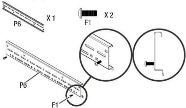
- Attach two M6 x 16 hex socket head screws (F3) to the bracket (P1) as shown.
text_image
P6 X 1 F1 X 2 P6 F1Pt: Bracket (1) F3: M6 x 16 hex socket head screws (2)
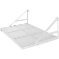
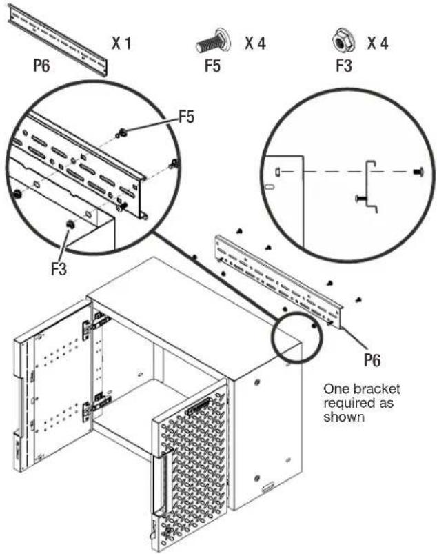
- Attach the bracket (P1) to the wall cabinet's back top.
text_image
P6 X 1 F5 X 4 F3 X 4 F5 F3 P6 One bracket required as shownPt: Bracket (1) F1: M6 round head square neck bolts (4)
F2: M6 hex flange nuts (4)
■ Attach the bracket (P1) to the wall cabinet's back top with four M6 round head square neck bolts (F1) and four M6 flange nuts (F2).
ASSEMBLY INSTRUCTIONS
- Hang the wall cabinet onto the GearTrack® channel.
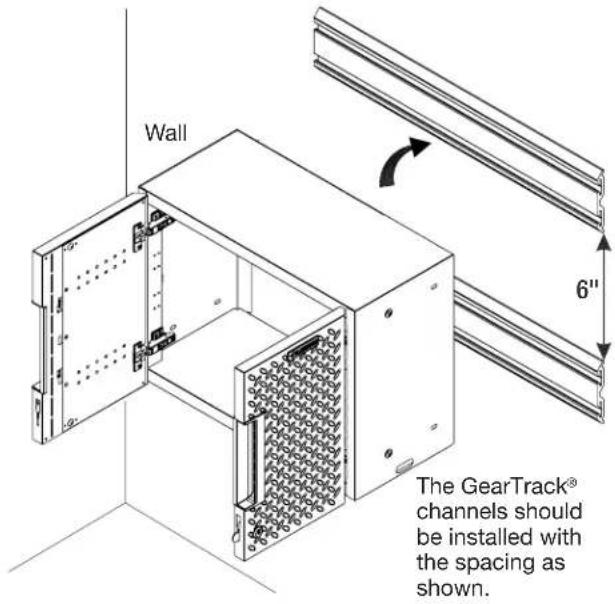
text_image
Wall 6" The GearTrack® channels should be installed with the spacing as shown.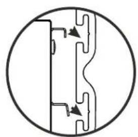
natural_image
Pure mechanical cross-section diagram without any text, numbers, or symbols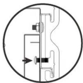
natural_image
Pure mechanical diagram showing a cross-section of a valve or connector with no text, numbers, or symbols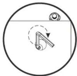
natural_image
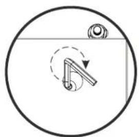
Simple line drawing of a mechanical component inside a circular frame, with no text or symbols present.Tighten the M6 x 16 hex socket head screws from the inside of the wall cabinet
■Make sure the bracket is fully engaged in the wall slots as shown. Tighten the pre-attached M6 x 16 hex socket head screws fully into the bracket and make sure they go into the wall slots.
NOTE: If installing the wall cabinet on GearTrack® channels, a second channel must be installed 6"(15.24cm) below the bottom of the supporting channel so the cabinet will hang level.
NOTE: For installation of the Gladiator® GearTrack® channels, please refer to the manual instructions included with the Gladiator® GearTrack® channels.
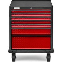
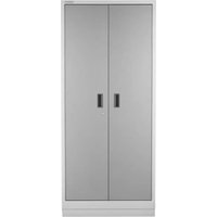
Install the 24"Flex 2-door Base Cabinet
NOTE: Flex Brackets are sold individually and Gladiator® GearTrack® channels are sold separately.
- Install the brackets (P1) to the cabinet.
X2

X8

X8
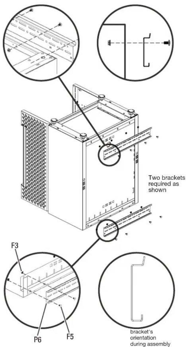
text_image
Two brackets required as shown F3 P6 F5 bracket's orientation during assemblyP1: Bracket (2) F1: M6 round head square neck bolts (8)
F2: M6 hex flange nuts (8)
■Temporarily turn the base cabinet upside down as shown.
■ Attach the brackets to the back of the base cabinet as shown with eight M6 round head square neck bolts (F5) and eight M6 flange nuts (F3).
ASSEMBLY INSTRUCTIONS
WARNING
Excessive Weight Hazard
Use two or more people to move and install cabinet.
Failure to do so can result in back or other injury.
- Hang the base cabinet onto the GearTrack® channels
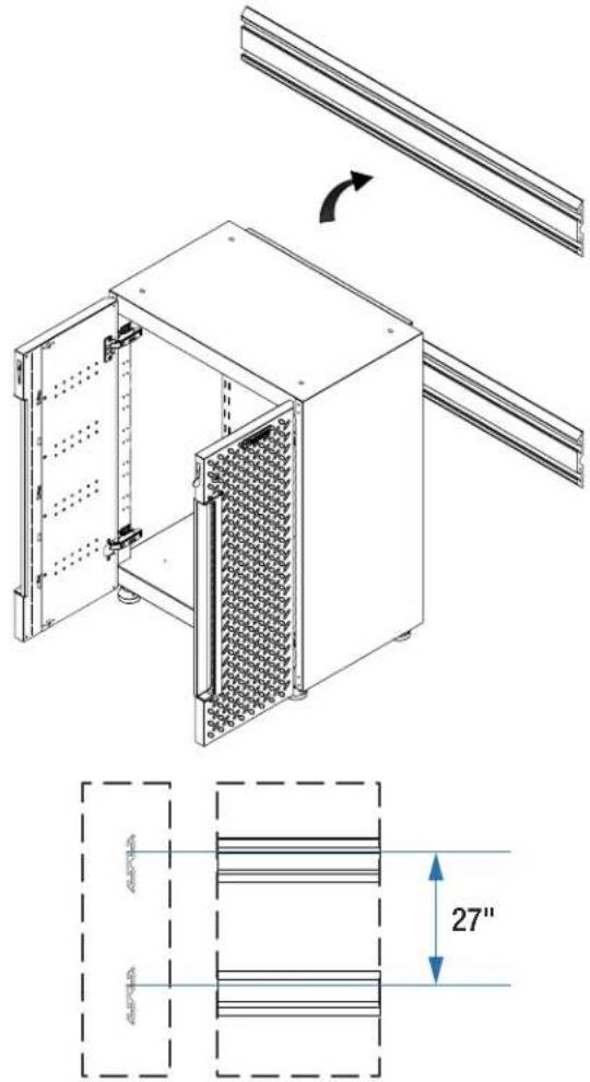
text_image
Technical diagram of a modular device with labeled components and dimensional annotationsThe GearTrack ^® channels should be installed with the spacing as shown.
natural_image
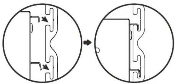
Diagram showing a mechanical component before and after transformation, with no visible text or symbols.■Hang the base cabinet onto the GearTrack ^® channels. Make sure the two brackets are fully engaged in the slots as shown.
NOTE: . For installation of the Gladiator® GearTrack® channels, please refer to the manual instructions included with the Gladiator® GearTrack® channels.
Install the 24" Flex 1-drawer 2-door Base Cabinet
NOTE: Flex Brackets are sold individually and Gladiator® GearTrack® channels are sold separately.
■Remove the drawer from the base cabinet.
■Follow the same procedure as the 24" 2-door base cabinet to attach the brackets and attach the cabinet onto the GearTrack® channels.
■Install the drawer back to the base cabinet.
WARRANTY
For warranty information:
In the U.S.A. call 1-866-342-4089 or visit our website at
www.GladiatorGW.com
In Canada call 1-800-807-6777 or visit our website at www.gladiatorgarageworks.ca
Limited Lifetime Parts Warranty for metal parts.
The warranty excludes incidental / inconsequential damages and failure due to misuse, abuse or normal wear and tear.
SÉCURITÉ DU SUPPORT
natural_image
Technical line drawing of a modular server unit with ventilation grilles and mounting brackets (no text or symbols)
text_image
30 po 30 ponatural_image
Diagram showing a mechanical component before and after transformation, with no visible text or symbols.Installer l'armoire murale de 24 po Flex
text_image
P6 X 1 F1 X 2 P6 F1natural_image
Pure mechanical cross-section diagram without any text, numbers, or symbols
natural_image
Pure mechanical diagram showing a cross-section of a valve or connector with no text, numbers, or symbols
natural_image
Simple line drawing of a mechanical component inside a circular frame, with no text or symbols present.natural_image
Technical line drawing of a modular device with internal panel structure and mounting bracket (no text or symbols)
text_image
27 ponatural_image
Diagram showing a mechanical component before and after assembly, with no visible text or symbolsnatural_image
Technical line drawing of a modular server cabinet with ventilation grilles and mounting brackets (no text or symbols)
text_image
30" 30"natural_image
Diagram showing a mechanical or electrical component before and after transformation, with no visible text or symbols.Instale el gabinete de pared Flex de 24"
text_image
P6 X 1 F1 X 2 P6 F1Pt: Soporte (1) F3: Tornillos de cabeza hueca hexagonal M6 x 16 (2)
natural_image
Pure mechanical cross-section diagram without any text, numbers, or symbols
natural_image
Pure mechanical diagram showing a valve or connector assembly without any text, numbers, or symbols