9EC-CIM - Water pump Little Giant - Free user manual and instructions
Find the device manual for free 9EC-CIM Little Giant in PDF.


User questions about 9EC-CIM Little Giant
0 question about this device. Answer the ones you know or ask your own.
Ask a new question about this device
Download the instructions for your Water pump in PDF format for free! Find your manual 9EC-CIM - Little Giant and take your electronic device back in hand. On this page are published all the documents necessary for the use of your device. 9EC-CIM by Little Giant.
USER MANUAL 9EC-CIM Little Giant
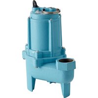
This submersible pump is designed for use in basins or pumping stations and is suitable for pumping clean water or effluent gray water with up to 3/4" (19 mm) spherical semi-solids. Do not use the pump in applications where sewage or any other debris (gravel, sand, floating debris, etc.), abrasives, or corrosives are present.
The pump motor is equipped with an automatic restart thermal protector and may restart unexpectedly. Activation of the thermal protector indicates that the motor is overloaded or overheated, which may be due to application problems, such as a clogged pump impeller, a switch stuck in the ON
natural_image
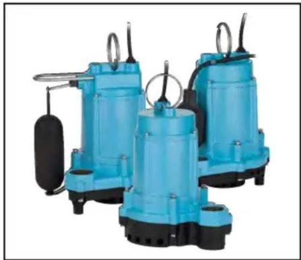
Three blue industrial water pumps with black bases and control knobs, no visible text or symbolsposition, a dry running of the pump, an air-sealed pump, a short pump cycle, an excessively high or low voltage supply, or a pump, motor, bearings, or seal that may have reached the end of its useful life.
This product is covered by a Limited Warranty for a period of 3 years from the date of original purchase by the consumer. For complete warranty information, refer to www.littlegiant.com
Specifications
| Model HP Volts Hz | Amps | Watts | Maximum Water Temperature | ||||
| FLA Start | |||||||
| 9EC | 4/10 | 115 60 | 7.5 14.5 800 | 140 °F(60 °C) | |||
| 208-230 | 50/60 4.0 | /4.0 10.0/10 | 0.0 820/900 | ||||
| 9ECH | 115 | 60 | 7 | 14.5 | 830 | ||
| 10ECH | 1/2 | 115 | 60 | 9 | 22 | 1030 | |
| Model | Gallons (Liters) per Minute, at Height | Shut Off | |||||
| 5 ft(1.5 m) | 10 ft(3 m) | 20 ft(6.1 m) | 30 ft(9.1 m) | 40 ft(12.2 m) | Feet(Meters) | PSI(Bar) | |
| 9EC | 70 (265) | 63 (238) | 45 (170) | 22 (83) | - | 37 (11.3) | 16.0 (1.1) |
| 9ECH | 70 (265) | 65 (246) | 50 (189) | 30 (114) | 9 (34) | 45 (13.7) | 19.5 (1.3) |
| 10ECH | 60 (227) | 55 (208) | 45 (170) | 30 (114) | 15 (57) | 60 (18.3) | 26 (1.8) |
| Model | Switch Type | ON Level | OFF Level |
| 9EC-CIA-SFS | Integral Snap-Action Float | 7 - 10 in. (18 - 25 cm) | 2 - 5 in. (5 - 13 cm) |
| 9EC-CIA-RF | Piggyback Mechanical Float | 12 - 15 in. (30 - 38 cm) | 6 - 9 in. (15 - 23 cm) |
| 9ECH-CIA-RF | |||
| 10ECH-CIA-SFS | Integral Snap-Action Float | 8 - 11 in. (20 - 28 cm) | 3 - 6 in. (8 - 15 cm) |
| 10ECH-CIA-RF | Piggyback Mechanical Float | 13 - 16 in. (33 - 41 cm) | 7 - 10 in. (18 - 25 cm) |
SAFETY INSTRUCTIONS
This equipment should be installed and serviced by technically qualified personnel who are familiar with the correct selection and use of appropriate tools, equipment, and procedures. Failure to comply with national and local electrical and plumbing codes and within Little Giant recommendations may result in electrical shock or fire hazard, unsatisfactory performance, or equipment failure.
Know the product's application, limitations, and potential hazards. Read and follow instructions carefully to avoid injury and property damage. Do not disassemble or repair unit unless described in this manual.
Refer to product data plate(s) for additional precautions, operating instructions and specifications.
Failure to follow installation or operation procedures and all applicable codes may result in the following hazards:
DANGER

Risk of death, personal injury, or property damage due to explosion, fire, or electric shock.
- Do not use to pump flammable, combustible, or explosive fluids such as gasoline, fuel oil, kerosene, etc.
- Do not use in explosive atmospheres or hazardous locations as classified by the NEC, ANSI/NFPA70.
- Do not handle a pump or pump motor with wet hands or when standing on a wet or damp surface, or in water.
- When a pump is in its application, do not touch the motor, pipes, or water until the unit is unplugged or electrically disconnected.
- If the power disconnect is out of sight, lock it in the open position and tag it to prevent unexpected application of power.
- If the disconnect panel is not accessible, contact the electric company to stop service.
WARNING

High voltages capable of causing severe injury or death by electrical shock are present in this unit.
- To reduce risk of electrical shock, disconnect power before working on or around the system. More than one disconnect switch may be required to de-energize the equipment before servicing.
- This product is supplied with a grounding conductor and grounding-type attachment plug. To reduce risk of electric shock, be certain that it is connected only to a properly grounded grounding-type receptacle. Do not remove the third prong from the plug. The third prong is to ground the pump to help prevent possible electric shock hazard. Do not use an extension cord.
- Check electrical outlets with a circuit analyzer to ensure power, neutral, and ground wires are properly connected. If not, a qualified, licensed electrician should correct the problem.
- Wire pump system for correct voltages.
- The flexible jacketed cord assembly mounted to the pump must not be modified in any way, with the exception of shortening the cord to fit into a control panel. Any splice between the pump and the control panel must be made within a junction box mounted outside of the basin and comply with the National Electrical Code. Employ a licensed electrician.
- Check local electrical and building codes before installation. The installation must be in accordance with their regulations as well as the most recent National Electrical Code (NEC).
- Do not remove the third prong from the plug, or cut plug from cord. These actions will void the warranty.
CAUTION

Risk of bodily injury, electric shock, or equipment damage.
- This equipment must not be used by children or persons with reduced physical, sensory or mental abilities, or lacking in experience and expertise, unless supervised or instructed. Children may not use the equipment, nor may they play with the unit or in the immediate vicinity.
- Equipment can start automatically. Always unplug the pump power cord and disconnect the electrical power before servicing the pump or switch.
- An inoperative or malfunctioning pump could lead to flooding, resulting in personal injury or property damage. Use with approved liquid level control with correct rating that matches marked motor input in full load amperes or service factor amperes.
- In applications where property damage and/or personal injury might result from an inoperative or leaking pump due to power outages, discharge line blockage, or any other reason, an automatic back-up system and/or an alarm should be installed.
- Do not run the pump dry. If run dry, the surface temperature of the pump will rise to a high temperature that could cause skin burns if touched and will cause serious damage to your pump.
- Do not oil the motor. The pump's motor housing is sealed, with a high-grade dielectric oil for heat transfer and lifetime lubrication. Use of other oils could cause serious electric shock and/or permanent damage to the pump.
- The pump has been evaluated for use with water only. Pump should only be used with liquids compatible with pump component materials. If the pump is used with liquids incompatible with the pump components, the liquid can cause failure to the electrical insulation system resulting in electrical shock.
- Operation of this equipment requires detailed installation and operation instructions provided in this manual. Read entire manual before starting installation and operation. End User should receive and retain manual for future use.
- Keep safety labels clean and in good condition.
- Do not use motor in swimming areas.
NOTICE
Risk of damage to pump or other equipment.
- Do not use this pump for pumping sea water, beverages, acids, chemical solutions, or any other liquid that promotes corrosion as this can result in damage to the pump.
- Do not run pump dry. For optimal cooling and to prolong the motor life, the liquid level being pumped should normally be above the top of the pump housing.
- This pump is not suitable for pond applications.
INSTALLATION
Typical Installation
text_image
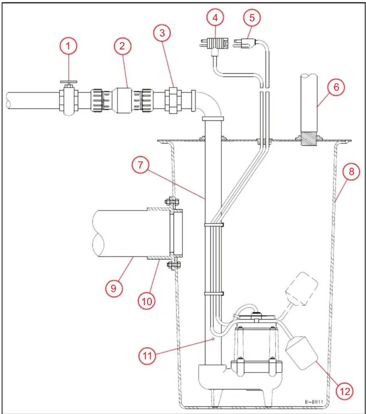
Technical diagram of a mechanical or fluidic device with numbered components, likely an industrial or laboratory apparatus.- Gate Valve 4. Switch Power 7. Discharge 10. Caulking Hub
- Check Valve 5. Pump Power 8. Gas Tight Basin 11. Air Bleed Hole
- Union 6. Vent 9. Intake 12.
Tethered Float (Refer to "Specifications" on page 1.)
Physical Installation
NOTICE
Risk of damage to pump or other equipment.
- Support pump and piping when assembling and when installed. Failure to do so may cause piping to break, pump to fail, motor bearing failures, etc.
- If the relief hole in the discharge pipe is not provided, the pump could "air lock" and will not pump water even though it will run.
- A missing, improperly installed, or malfunctioning check valve can cause a pump to short-cycle due to back-flow of the pumped fluid from the discharge plumbing back into the basin, significantly shortening the life of the pump.
NOTE: To test the operation before installing, refer to "Operation Testing" on page 6.
-
Install the pump in the center of a suitable gas-tight basin that is at least 1.5 ft in diameter and 2 ft deep and vented in accordance with local plumbing codes.
-
Place as close as possible to the water source to minimize suction piping length.
- Provide adequate room for future servicing, protection from freezing temperatures, flooding, and equipment drainage.
- Never place the pump directly on clay, earth, or gravel surfaces.
- Ensure sump is clean and free of nails, gravel, string, cloth, or other debris before installing.
IMPORTANT: Do not attempt to restrict the intake side of the pump.
- Connect discharge piping, using pipe joint compound at all connections.
• These pumps are available with 1.5" FNPT discharge.
- The discharge pipe should be as short as possible and contain as few elbows as possible.
- Piping should be the same diameter as the discharge port.
- If reduced flow rates are required, place a valve on the discharge side of the pump.
- If flexible vinyl tubing is used, a clamp can be used on the tubing to restrict the flow.
-
Install a union in the discharge line just above the basin cover.
-
Install a free-flow check valve in the discharge line that will easily pass 3/4" solids.
• Install the check valve in a horizontal position or at an angle of no more than 45^ . -
Tape the pump and switch cords to the discharge piping with electrical tape.
-
Add an air relief bleed hole 1/8" or 3/16" in diameter in the discharge pipe. Refer to "Typical Installation" on page 4.
- Drill this hole at a 45^ angle below the horizontal plane and away from the pump.
- Confirm that the pump is functioning as intended.
NOTE: It is normal for a stream of water to spray from the air bleed hole in the pump's plumbing. Confirm that this spray is captured within the basin.
- Place cover over basin.
Electrical Connections
▲ WARNING

Risk of severe injury or death by electrical shock.
• Always disconnect the electrical power before touching the pump, discharge or electrical plug when water is present in the area.
- Do not use the power cord for lifting the pump.
- Be certain that this pump is connected to a circuit equipped with a ground fault circuit interrupter (GFCI) device if required by code.
Connect the power cord to a constant source of power matching the pump nameplate voltage.
- The pump should be connected or wired to its own circuit, with no other electric receptacles or equipment in the circuit.
NOTE: Do not connect to a fan or any device that runs intermittently.
- The fuses or circuit breaker should use a 15 A breaker.
IMPORTANT: If the power cord is damaged, the whole unit must be replaced
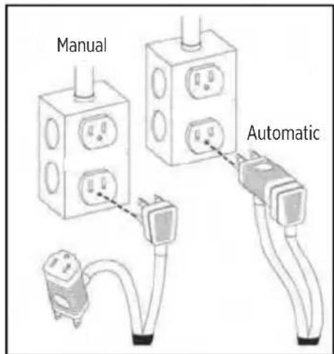
The 9EC-CIA-RF, 9ECH-CIA-RF and 10ECH-CIA-RF pumps have piggyback plugs on the switch cords.
- Plug the pump cord into the float switch cord.
- Plug the float switch cord into the outlet.
text_image
Manual AutomaticOPERATION TESTING
NOTICE
Risk of damage to pump or other equipment.
- If pump is run dry, it may damage pump and will void the warranty.
- Do not let the unit freeze. Freezing may cause cracking or distortion that may destroy the unit.
NOTE: If the unit is going to be idle for a period of time, refer to "Cleaning Impeller and Volute" on page 8.
Testing Automatic Pump Operation
The 9EC-CIA-SFS and 10ECH-CIA-SFS automatic pumps are equipped with an integral float-operated mechanical switch which will turn the pump on when water level reaches the levels shown in 'Specifications" on page 1.
The 9EC-CIA-RF, 9ECH-CIA-RF, and 10ECH-CIA-RF pumps have automatic switches with piggyback plugs on the switch cords.
- Remove the rubber plug on the basin cover in order to observe switch operation.
- Plug the power cord into a grounded receptacle with voltage indicated on the pump nameplate.
- Be sure the gate valve in the discharge line is open.
-
Run water into the basin until the pump is activated.
-
Make sure the pump and its float switch are functioning as intended.
-
Confirm that no potential obstructions exist that could inhibit switch operation.
-
Verify the ON/OFF levels are within specification.
-
Confirm that there are no leaks in the pump discharge plumbing and main home drain pipe plumbing. Refer to "Physical Installation" on page 5.
- Allow the pump to operate through several ON/OFF cycles.
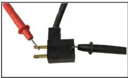
- Use an ohmmeter to check for continuity between the incoming and outgoing connections of the piggyback plug while raising and lowering the float.
natural_image
Close-up of a black electrical plug with two gold pins, connected to a red and black probe (no text or symbols visible)Testing Manual Pump Operation
CAUTION


Risk of bodily injury, electric shock, or equipment damage.
- Manual, continuous pump operation should be used only for emergencies, or when a large volume of water is to be pumped. The pump must be continuously monitored during operation and disconnected from power before the pump runs dry.
- If an accessory float switch or other liquid level control is installed, refer to manufacturer's instructions. Failure to install control in compliance with national and local electrical and plumbing codes and within manufacturer's recommendations may result in electrical shock or fire hazard, unsatisfactory performance, or equipment failure.
The 9EC-CIM, 9ECH-CIM, and 10ECH-CIM manual pumps do not include an automatic liquid level control.
- Connect a discharge hose to the pump's discharge port.
- Place pump into a basin or test reservoir.
- Direct the opposite end of the discharge hose back into the basin or test reservoir so that the water discharged from the hose during testing will be contained.
- Secure the hose to prevent the water pressure created during testing from causing it to exit the basin or test reservoir.
- If there is a valve on the discharge hose, be sure it is open.
- Using a separate water source, fill the basin or test reservoir until the pump is fully submerged.
NOTE: Do not overfill the basin or test reservoir.
-
Turn on the pump.
-
If the pump is hardwired, turn on the circuit breaker for the pump's power circuit.
-
If the pump is provided with an attachment plug on the power cord, plug the pump's power cord into a ground fault circuit interrupter (GFCI) receptacle with voltage indicated on the pump nameplate.
-
Confirm that the pump is functioning as intended. Refer to "Physical Installation" on page 5.
-
If the pump is functioning as intended, pump is ready for use. Disconnect power from the pump if removing it from a test reservoir.
MAINTENANCE
▲ WARNING


Risk of severe injury or death by electrical shock, high temperatures, or pressurized fluids.
- Always unplug the pump power cord in addition to removing the fuse or shutting off the circuit breaker before working on the pump or switch.
- Let pump cool for a minimum of 2 hours before attempting to service. Submersible pumps contain oil that becomes pressurized and hot under normal operating conditions.
NOTICE
Risk of damage to pump or other equipment.
- This unit is permanently lubricated. Oiling is not required. Do not open the sealed portion of the unit or remove housing screws.
- Do not remove the motor housing cover, impeller, or seals. Warranty is void if the motor housing cover, impeller, or seals have been removed. Repairs on the motor or impeller require special tools.
Periodic Service
Inspect and test the pump system condition and operation every three months—more frequently in heavy use applications.
- Check the power cords and electrical outlet for damage or corrosion.
IMPORTANT: If the power cord is damaged, the whole unit must be replaced.
- Remove all debris (gravel, sand, floating debris, etc.) from the basin.
- Check the pump system components (basin, pump, switch, etc.) for any build-up (sludge, sediment, minerals, etc.) that would inhibit functionality of the components. If significant, remove build-up or replace affected components.
- Confirm all flexible coupling hose clamps are fully engaged with plumbing and fully tightened.
- Test operation of the pump system. Refer to "Operation Testing" on page 6.
Cleaning Impeller and Volute
- Disconnect power to the pump.
- Remove the five bolts that hold the volute to the motor housing.
- Separate the volute from the motor housing.
IMPORTANT: Do not remove the motor housing bolts or screws.
- Clean the impeller and the volute passage.
IMPORTANT: Do not use strong solvents on the impeller. Do not remove the impeller.
- Be sure the impeller turns freely.
- Reattach the volute to the motor housing, securing it with the four bolts.
Troubleshooting
| Problem Probable Causes Corrective Action | ||
| Pump does not turn on | Pump not plugged in Plug in pump. | |
| Circuit breaker off or fuse removed Turn on | circuit breaker or replace fuse. | |
| Accumulation of trash on float Clean float. | ||
| Float obstruction Check float path and provide clearance. | ||
| Defective switch | Models with piggyback switches: replace switch. Models with integral switches: replace pump. | |
| Defective motor Replace pump. | ||
| Pump will not shut off | Float or float rod obstruction | Check float and float rod path and provide clearance. |
| Pump is air locked. Remove pump and clean air bleed hole. | ||
| Liquid inflow matches pump capacity. Larger pump required. | ||
| Defective switch | Models with piggyback switches: replace switch. Models with integral switches: replace pump. | |
| Pump runs but does not discharge liquid | Check valve installed backwards | Check flow indicating arrow on check valve body to ensure proper installation. |
| Check valve stuck or plugged | Remove check valve and inspect for proper operation. | |
| Lift too high for pump Check rated pump performance. | ||
| Inlet to impeller plugged Pull pump and clean. | ||
| Pump is air locked. Remove pump and clean air bleed hole. | ||
| Pump does not deliver rated capacity | Lift too high for pump Check rated pump performance. | |
| Low voltage, speed too slow | Check that supply voltage matches the nameplate rating. | |
| Impeller or discharge pipe is clogged | Pull pump and clean. Check pipe for scale or corrosion. | |
| Impeller wear due to abrasives Replace pump. | ||
| Pump cycles continuously | No check valve in long discharge pipe allowing liquid to drain back into basin | Install a check valve in discharge line. |
| Check valve leaking Inspect check valve for correct operation. | ||
| Basin too small for inflow Install larger basin. | ||
| Water sprays out of a hole in the discharge pipe. | There should be a bleed hole in the discharge pipe that allows trapped air to escape from the pump, preventing air lock. Water spraying out of this hole is completely normal. | No corrective action is required. |
Replacement Parts
text_image
Technical diagram showing three different mechanical device configurations with labeled parts and a magnified inset of a coiled cable component.| Item Description Part Number | ||
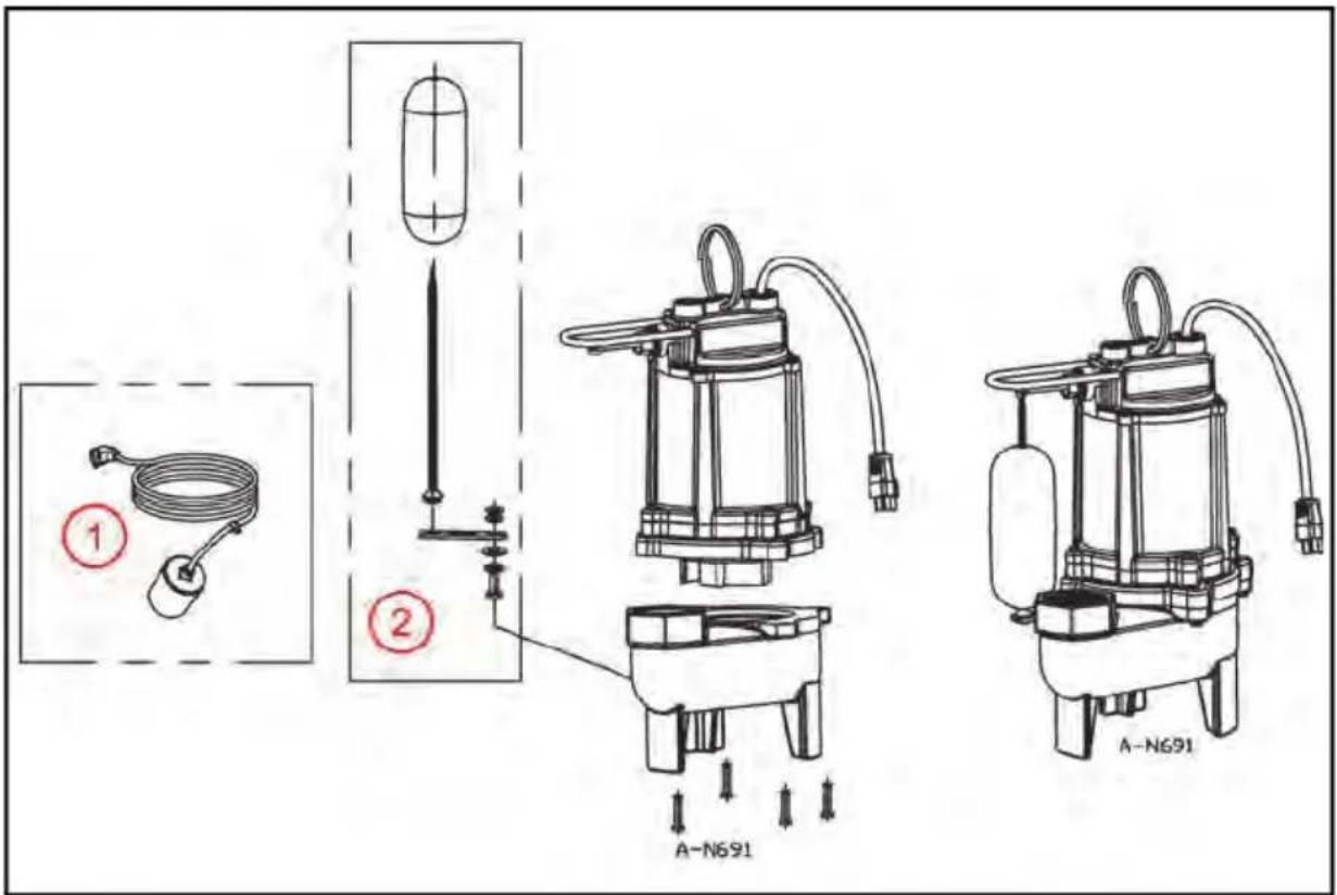
| 1 | RF Series Piggyback Float Switch 115 V, 20 FT Cord 599210 | |
| RF Series Piggyback Float Switch 115 V, 30 FT Cord 599121 | ||
| RF Series Piggyback Float Switch 230 V, 20 FT Cord 599209 | ||
| 2 SFS | Series Float Assembly 599139 | |