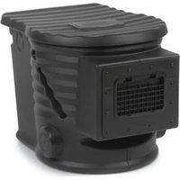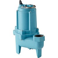
Pit+Plus Jr - Water pump Little Giant - Free user manual and instructions
Find the device manual for free Pit+Plus Jr Little Giant in PDF.


User questions about Pit+Plus Jr Little Giant
0 question about this device. Answer the ones you know or ask your own.
Ask a new question about this device
Download the instructions for your Water pump in PDF format for free! Find your manual Pit+Plus Jr - Little Giant and take your electronic device back in hand. On this page are published all the documents necessary for the use of your device. Pit+Plus Jr by Little Giant.
USER MANUAL Pit+Plus Jr Little Giant
Pit+Plus JR & SR Systems
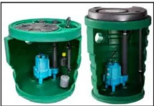
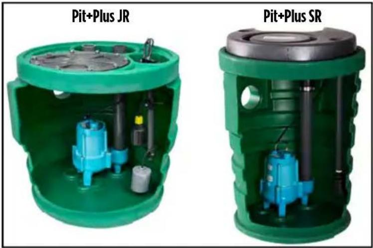
Pit+Plus JR and SR systems are designed for use in residential applications to collect sewage, effluent, drainage, or seepage water. These systems divert this away from structures, landscapes prone to erosion, and areas with poor drainage. Install only in indoor applications, isolated from traffic.
The system is equipped with floats or an External Control Module (ECM ^™ ). The ECM ^™ is an advanced control switch for a sewage basin.
natural_image
Two green industrial cylindrical containers with internal blue hydraulic pumps and black pipes, shown from open and closed views (no text or symbols visible)This product is covered by a Limited Warranty for a period of 3 years from the date of original purchase by the consumer. For complete warranty information, refer to www.LittleGiant.com
Specifications
| HP Volts Hz Amps | Discharge in (mm) | Watts | Shut Off ft (m) | |||
| 4/10 | 115 60 | 8 - 870 20 | (6.1) | |||
| 1/2 | 11 2 (51) | 1230 25 | (7.62) | |||
| 11.5 3 (76.2) | ||||||
| 1 12.5 | 2 (51) | 1330 53 | (16.15) | |||
SAFETY INSTRUCTIONS
This equipment should be installed and serviced by technically qualified personnel who are familiar with the correct selection and use of appropriate tools, equipment, and procedures. Failure to comply with national and local electrical and plumbing codes and within Little Giant recommendations may result in electrical shock or fire hazard, unsatisfactory performance, or equipment failure.
Know the product's application, limitations, and potential hazards. Read and follow instructions and those provided with the pump carefully to avoid injury and property damage. Do not disassemble or repair unit unless described in this manual.
Failure to follow installation or operation procedures and all applicable codes may result in the following hazards:
▲ WARNING

Risk of severe injury or death by electrical shock.
- Check local electrical and building codes before installation. The installation must be in accordance with their regulations as well as the most recent National Electrical Code (NEC) and the Occupational Safety and Health Act (OSHA).
- This product is supplied with a grounding conductor and grounding-type attachment plug. To reduce risk of electric shock, be certain that it is connected only to a properly grounded grounding-type receptacle. Do not remove the third prong from the plug. The third prong is to ground the pump to help prevent possible electric shock hazard. Do not use an extension cord.
CAUTION
Risk of bodily injury, electric shock, or equipment damage.
- This equipment must not be used by children or persons with reduced physical, sensory or mental abilities, or lacking in experience and expertise, unless supervised or instructed. Children may not use the equipment, nor may they play with the unit or in the immediate vicinity.
- Do not run the pump dry. If run dry, the surface temperature of the pump will rise to a high temperature that could cause skin burns if touched and will cause serious damage to your pump.
- Operation of this equipment requires detailed installation and operation instructions provided in this manual for use with this product. Read entire manual before starting installation and operation. End User should receive and retain manual for future use. Keep safety labels clean and in good condition. Keep work area clean, well-lit, and uncluttered.
- Wear safety glasses while installing or performing maintenance on the pump.
INSTALLATION
Physical Installation
- Place the system indoors, in an isolated area away from foot traffic, as the covers are not suitable for heavy traffic loads.
- Remove cover and set aside.
- Remove bolts and washers from pump access cover and set cover aside.
- Make sure the pump is upright and standoff feet are located within the three integral torque stops.
- Verify the pump discharge pipe is securely connected to the exit pipe inside the basin with the flexible coupling.
-
Reconnect the pump discharge pipe with flexible coupling and band clamps, if necessary.
-
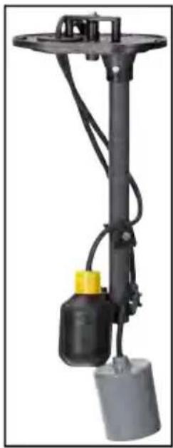
Examine the level control float switch and alarm float, if included.
- Make sure the float pole is secured to bottom of control cover and there are no obstructions.
- Refer to the float switch and/or alarm switch instruction manuals.
IMPORTANT: Do not change the lengths of the float pole assembly's cord grips.
-
For systems with an ECM ^™ , make sure the sensor tube extending from bottom of control module is not damaged and unobstructed to allow air to pass through the vent tube.
-
Install piping.
-
Remove temporary pipe caps from the vent and discharge pipes.
- Connect the basin discharge pipe to drain pipe.
• Install a check valve (not included) near the basin, horizontally or at an angle less than 45^ . - Drill a 3/16" hole in the discharge pipe, approximately 2" above discharge connections.
-
Connect the Pit+Plus vent pipe to the vent pipe.
-
Make electrical connections.
-
Insert piggyback plug to a 115 V outlet.
- Plug the pump power cord into back of piggyback plug.
Operation Testing
- Fill basin with water to activate controls and pump.
-
For systems with an ECM ^™ , make sure the pump operates on manual control:
-
Disconnect electrical power.
- Remove piggyback plug from the outlet.
- Plug pump power cable into outlet.
- Turn on electrical power.
NOTE: If pump operates on manual control, but not in automatic control, the switch is in failure mode. Refer to "Troubleshooting" on page 6.
- If the unit does not operate, refer to the troubleshooting table in the pump owner's manual.
MAINTENANCE
Refer to "Replacement Parts" on page 4 for names and relative location of all components. Consult the instruction sheet illustrations for proper assembly and disassembly of your Little Giant pump.
Pump Replacement
Disassembly
- Disconnect pump and switch from power supply.
- Remove pump access cover and set aside.
- Remove cord grommet from the switch access cover.
- Separate the pump power cord from the grommet.
- Loosen the 2 band clamps on the flexible coupling connecting the pump and basin discharge pipes.
- Slide flexible coupling down.
- Feed power cord through the cord grommet opening and remove the pump.
- Remove discharge pipe from pump
Reassembly
- Connect discharge pipe to replacement pump.
- Install replacement pump into basin so the lower and basin discharge pipes are aligned.
- Center the flexible adapter on both discharge pipes. Tighten the band clamps.
- Feed power cord through the cord grommet opening and reinstall cord grommet.
- Route the pump cord behind the discharge pipe.
- Remove any cord slack that might potentially interfere with control float or alarm float operation.
- Reinstall pump access cover.
- Connect pump and switch to power supply.
Float Switch and Alarm Switch Replacement Disassembly
- Disconnect pump and switch from power supply.
- Remove cord grommet from switch housing.
- Remove all cords from cord grommet.
- Remove the switch module from the basin by unscrewing its 6 bolts.
- Feed the pump cord through the grommet opening until the switch module is free.
- Remove the float switch by loosening the plastic wing nut opposite the cord grip.
NOTE: It is not necessary to remove the wing nut completely.
Reassembly
- Install the new float switch.
- Make sure the cord tether length (distance between the cord grip and float housing) is 3.5 to 3.75 inches for correct liquid level control.
- Feed the float switch cord(s) and the pump cord through the cord grommet opening.
- Secure the switch module to the basin with 6 bolts.
- Feed the cords into the cord grommet and install the grommet into the switch module.
- Remove any cord slack that could interfere with the control float or alarm float.
- Connect the switch and pump to power supply.
External Control Module (ECM™) Replacement
- Disconnect pump and switch from power supply.
- Remove cord grommet from the switch access cover.
- Separate the pump power cord from the grommet.
- Remove the switch module from the basin by unscrewing its 6 bolts.
- Feed the pump cord through the cord grommet opening until the switch module is free.
- Thread the pump cord through the cord grommet opening of the replacement ECM ^™ .
- Install the new ECM ^™ module to basin and secure with 6 bolts.
- Insert the pump cords in cord grommet.
- Install the cord grommet into the switch module.
- If using an alarm float, remove any cord slack that could interfere with its operation.
natural_image
Mechanical device with black body, yellow cap, and gray base (no visible text or symbols)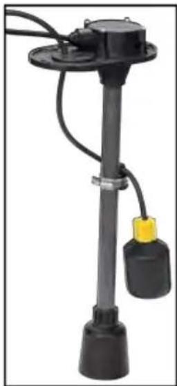
natural_image
Black industrial electrical outlet device with cylindrical base and yellow connector (no visible text or symbols)Replacement Parts
Pump Models
| Model Description | Order Number | |
| 9SC-CIM 115 V, 60 Hz | 20 ft 509413 | |
| 10SC-CIM | 115 V, 60 Hz, 20 ft, 2 in 511432 | |
| 115 V, 60 Hz, 20 ft, 3 in 511435 | ||
| 16G-M151-20 115 V, 60 Hz | 20 ft, 2 in 509809 |
*Do not install 16G-M151-20 model pump on ECM™ equipped units.
Cover & Hardware Kits
| Item No. Description |
| 113388 Bolts, washers, gasket, and wing bolts for finish cover |
| 113389 Main basin cover, bolts, washers, gasket, and wing bolts for finish cover |
Attachment Assemblies
| Assembly Type Pit+Plus Type Item No. Model No. Alarm Hardware | |||
| Float | JR | 513633 PPJFNA No | |
| 513634 PPJFWA Yes | |||
| SR | 513631 PPSFNA No | ||
| 513632 PPSFWA Yes | |||
| ECMTM | JR | 513637 PPJENA No | |
| 513638 PPJEWA Yes | |||
| SR | 513635 | PPSENA No | |
| 513636 | PPSEWA Yes | ||
Basin Assemblies
text_image
Pit+Plus JR Pit+Plus SR| Pit+Plus Type | Item No. Model No. Discharge (in) | Vent (in) | ||
| JR | 513615* | PPJ2V2D 2 | 2 | |
| 513616 | PPJ2V3D | 3 | ||
| 513617 | PPJ3V3D | 3 | ||
| 513618 | PPJ3V2D | 2 | ||
| SR | 513611* | PPS2V2D | 2 | |
| 513612 | PPS2V3D | 3 | ||
| 513613 | PPS3V3D | 3 | ||
| 513614 | PPS3V2D | 2 | ||
*Discharge pipe needs to be shortened by 1.5 inches when used with 16G-M151-20 Model pump.
Troubleshooting
| Problem Probable Causes Corrective Action | ||
| Pump will not operate | Circuit breaker tripped or power turned off | Reset circuit breaker or correct electrical supply. |
| Switch failure | Disconnect electrical power. Remove the piggyback plug from the outlet. Plug the pump power cable into the outlet. Turn on electrical power. If the pump operates, the switch is in failure mode. | |
| Pump runs, but does not discharge liquid | Blocked discharge pipe Clean discharge pipe. | |
| Blocked vent pipe | Clean vent pipe. Make sure the air admittance valves are not restricting the free passage of air in the vent pipe. | |
| Check valve installed backwards | Check flow indicating arrow on check valve body to ensure it is installed properly. | |
| Check valve stuck or unplugged | Remove check valve and inspect for proper operation. | |
| Lift too high for pump Check rating table. | ||
| Inlet to impeller plugged Pull pump and clean. | ||
| Pump is air-locked | Consult the pump installation instructions. Make sure the 3/16" hole in the discharge pipe inside the basin is not present or is blocked to allow air to escape the pump volute. | |
| Pump does not shut off when operating in automatic control (with ECMTM) | Diaphragm switch Replace switch. | |
| Weak or hardened rubber diaphragm | Replace rubber diaphragm. | |
| Plugged vent tube Clear vent tube of any obstructions. | ||
| Dirt or sediment lodged between retainer ring and rubber diaphragm causing contact to remain closed | Clean area around rubber diaphragm. | |
| Pump is air locked | Shut power off for approximately 1 minute, then restart. Repeat several times to clear air from pump. Check the air bleed hole, refer to "Physical Installation" on page 2. | |
| Liquid inflow matches pump capacity | Larger pump required. | |
| Defective switch | Disconnect switch, check with ohmmeter, open-infinitive resistance, closed-zero. | |
| Loose connection in level control wiring | Check control wiring. | |
| Pump does not deliver rated capacity | Lift too high for pump Check rated pump performance. | |
| Low voltage, speed too slow | Check for proper supply voltage to make certain it corresponds to nameplate voltage. | |
| Impeller or discharge pipe is clogged | Pull pump and clean. Check pipe for scale or corrosion. | |
| Impeller wear due to abrasives | Replace worn impeller. | |
| Pump cycles continually | No check valve in long discharge pipe allowing liquid to drain back into sump | Install a check valve in discharge line. |
| Check valve leaking Inspect check valve for correct operation. | ||
| Basin too small for inflow Install larger basin. | ||
Sistemas Pit+Plus JR y SR
natural_image
Two green industrial cylindrical containers with internal blue hydraulic pumps and black pipes, shown from open and closed angles (no text or symbols visible)Especificaciones
| HP Voltios Hz Amperios | Descarga mm (pulg) | Vatios | Apagado m (pies) | |||
| 4/10 | 115 60 | 8 - 870 6.1 (20) | ||||
| 1/2 | 11 51 (2) | 1230 7.62 | (25) | |||
| 11.5 76.2 (3) | ||||||
| 1 12.5 | 51 (2) 1330 | 16.15 (53) | ||||
natural_image
Mechanical device with black lever and yellow component, no visible text or symbolsnatural_image
Mechanical device with black cylindrical components and yellow connectors, no visible text or symbolsPiezas de repuesto
Modelos de bombas
| Modelo Descripción Número de pedido | ||
| 9SC-CIM 115V, 60 Hz, 20 | FT 509413 | |
| 10SC-CIM | 115 V, 60 Hz, 20 FT, 2" 511432 | |
| 115 V, 60 Hz, 20 FT, 3" 511435 | ||
| 16G-M151-20 115 V, 60 Hz, 20 FT, 2" 509809 | ||
text_image
Pit+Plus JR Pit+Plus SR| Tipo de Pit+Plus | Artículo No. | Modelo | Descarga (pulg) | Ventilación (pulg) |
| JR | 513615 | PPJ2V2D | 2 | 2 |
| 513616 | PPJ2V3D | 3 | ||
| 513617 | PPJ3V3D | 3 | ||
| 513618 | PPJ3V2D | 2 | ||
| SR | 513611 | PPS2V2D | 2 | |
| 513612 | PPS2V3D | 3 | ||
| 513613 | PPS3V3D | 3 | ||
| 513614 | PPS3V2D | 2 |
natural_image
Two green industrial cylindrical enclosures with internal blue hydraulic components and black pipes (no text or symbols visible)natural_image
Mechanical device with black cylindrical body, yellow cap, and gray base (no visible text or symbols)natural_image
Black industrial electrical outlet device with two cylindrical components and a yellow tag (no visible text or symbols)text_image
Pit+Plus JR Pit+Plus SR| Pit+Plus Numéro d'article Modèle | Refoulement (po) Ventilation (po) | ||
| JR | 513615 PPJ2V2D 2 | 2 | |
| 513616 PPJ2V3D | 3 | ||
| 513617 PPJ3V3D | 3 | ||
| 513618 PPJ3V2D | 2 | ||
| SR | 513611 PPS2V2D | 2 | |
| 513612 PPS2V3D | 3 | ||
| 513613 PPS3V3D | 3 | ||
| 513614 PPS3V2D 2 | |||