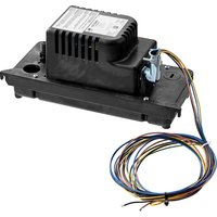
VCCA-20-P - Water pump Little Giant - Free user manual and instructions
Find the device manual for free VCCA-20-P Little Giant in PDF.


User questions about VCCA-20-P Little Giant
0 question about this device. Answer the ones you know or ask your own.
Ask a new question about this device
Download the instructions for your Water pump in PDF format for free! Find your manual VCCA-20-P - Little Giant and take your electronic device back in hand. On this page are published all the documents necessary for the use of your device. VCCA-20-P by Little Giant.
USER MANUAL VCCA-20-P Little Giant
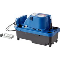
VCCA-20-P Condensate Pump for Plenum Applications
The VCCA-20-P pump is designed to be used in plenum applications and is compliant with UL standard UL2043, “Fire Test for Heat and Visible Smoke Release for Discrete Products and Their Accessories Installed in Air-handling Spaces.”
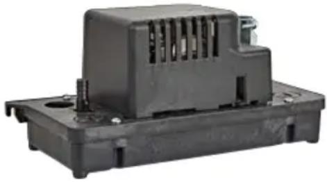
This condensate pump automatically removes condensate water that drips from an air conditioner evaporator coil, refrigeration equipment coil, condensing furnace, or condensing boiler. The pump is controlled by a float switch mechanism, which automatically starts and stops the pump.
natural_image
Exterior view of a black plastic electrical contactor housing (no text or symbols visible)All models also include a high water level switch, which opens
a thermostat circuit when the pump reservoir is full, stopping production of condensate. Alternatively, this switch can be reconfigured to close a circuit, which can operate an external alarm or relay, (purchased separately).
This product is covered by a Limited Warranty for a period of 12 months from the date of original purchase by the consumer. For complete warranty information, refer to www.LittleGiant.com
Specifications
| Model Volts | HZ Amps | Watts | Shut | Off | ||
| VCCA-20-P | 115 60 | 1.5 | 93 20' | (6.1 m) | ||
| 230 50/60 | 0.6/0.5 | 75 17' | (5.2 m) | |||
SAFETY INSTRUCTIONS
This equipment should be installed and serviced by technically qualified personnel who are familiar with the correct selection and use of appropriate tools, equipment, and procedures. Failure to comply with national and local electrical and plumbing codes and within Little Giant recommendations may result in electrical shock or fire hazard, unsatisfactory performance, or equipment failure.
Know the product's application, limitations, and potential hazards. Read and follow instructions carefully to avoid injury and property damage. Do not disassemble or repair unit unless described in this manual.
Refer to product data plate(s) for additional precautions, operating instructions and specifications.
Failure to follow installation or operation procedures and all applicable codes may result in the following hazards:
DANGER

Risk of death, personal injury, or property damage due to explosion, fire, or electric shock.
- Do not use to pump flammable, combustible, or explosive fluids such as gasoline, fuel oil, kerosene, etc.
- Do not use in explosive atmospheres or hazardous locations as classified by the NEC, ANSI/NFPA70.
- Do not handle a pump or pump motor with wet hands or when standing on a wet or damp surface, or in water.
- When a pump is in its application, do not touch the motor, pipes, or water until the unit is unplugged or electrically disconnected.
- If the power disconnect is out of sight, lock it in the open position and tag it to prevent unexpected application of power.
▲ WARNING

Risk of severe injury or death by electrical shock.
• To reduce risk of electrical shock, disconnect power before working on or around the system.
- Wire pump system for correct voltage.
- Be certain that this pump is connected to a circuit equipped with a ground fault circuit interrupter (GFCI) device if required by code.
- Check electrical outlets with a circuit analyzer to ensure power, neutral, and ground wires are properly connected.
- Some pumps are supplied with a grounding conductor and grounding-type attachment plug. To reduce risk of electric shock, be certain that it is connected only to a properly grounded grounding-type receptacle. Do not remove the third prong from the plug. The third prong is to ground the pump to help prevent possible electric shock hazard.
- Some pumps are supplied with lead wires and are intended to be hardwired using a junction box or other approved enclosure. The pumps include a grounding connector. To reduce risk of electric shock, be certain that it is properly connected to ground.
- In a 230 V direct wire installation, one side of the line going to the pump is always electrically energized, regardless of whether the liquid level control switch is open or closed. To avoid hazards when installing or servicing, install a double-pole disconnect near the pump installation.
- The flexible jacketed cord assembly mounted to the pump must not be modified in any way, with the exception of shortening the cord to fit into a control panel. Any splice between the pump and the control panel must be made within a junction box and comply with the National Electrical Code.
- Check local electrical and building codes before installation. The installation must be in accordance with their regulations as well as the most recent National Electrical Code (NEC) and the Occupational Safety and Health Act (OSHA).
- Do not use the power cord for lifting the pump.
- Do not use an extension cord.
- The pump should only be used with liquids compatible with pump component materials. If the pump is used with liquids incompatible with the pump components, the liquid can cause failure to the electrical insulation system resulting in electrical shock.
CAUTION


Risk of bodily injury, electric shock, or equipment damage.
- This equipment must not be used by children or persons with reduced physical, sensory or mental abilities, or lacking in experience and expertise, unless supervised or instructed. Children may not use the equipment, nor may they play with the unit or in the immediate vicinity.
- Equipment can start automatically. Lockout-Tagout before servicing equipment.
- An inoperative or malfunctioning pump could lead to flooding, resulting in personal injury or property damage.
- The pump has been evaluated for use with water only. Pump should only be used with liquids compatible with pump component materials. If the pump is used with liquids incompatible with the pump components, the liquid can cause failure to the electrical insulation system resulting in electrical shock.
- Operation of this equipment requires detailed installation and operation instructions provided in this manual. Read entire manual before starting installation and operation. End User should receive and retain manual for future use.
NOTICE
Risk of damage to pump or other equipment.
- Before installing pump, allow air conditioner to cycle several times, collecting condensate in a separate container to help flush any residual oils that may remain in the system. Failure to flush the system can result in damage to the pump and drain line plumbing components.
- When operating in a gas furnace environment, care must be taken to ensure acidity of condensate does not fall below the average pH of 3.4 (to prevent a localized pocket of acid that acts like a battery causing pitting) by routinely cleaning or flushing tank with fresh water.
- Support pump and piping when assembling and when installed. Failure to do so may cause piping to break, pump to fail, motor bearing failures, etc.
- Do not install the pump in a manner that will subject it to splashing or spraying.
- Periodically inspect pump and system components. Regularly check hoses for weakness or wear, making certain that all connections are secure.
- Schedule and perform routine maintenance as required and in accordance with the Maintenance section of this manual.
- Pump is for indoor use only.
INSTALLATION
Physical Installation
• Install the pump on a flat surface.
- Make sure the surface will support the combined weight of the pump and water filled tank.
- The air vent openings around the motor housing must not be blocked or obstructed to allow the free flow of air.
- Ensure that the pump is level and the inlet is below the coil drain.
Piping Connections
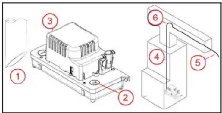
- Cut end of pipe(s) from evaporator or furnace drain at a 45° angle to prevent pipe(s) from sealing closed against the tank's floor.
- Route drain pipe downward into pump inlet opening.
- For plenum applications, use metal tubing such as copper, from evaporator.
text_image
Technical diagram of a mechanical assembly with numbered components, likely for assembly or maintenance instructions.- To open one of the closed inlets, insert a screw driver into the slot and twist to remove. Be sure the knockout plug does not fall into the tank.
- Install outlet tubing or piping onto outlet check valve.
NOTE: When verifying installation, keep in mind a click will be heard when the check valve is securely locked.
- With the factory installed 3/8" hose barb, use 3/8" inside diameter maximum tubing or piping to prevent excessive backflow to unit and secure with cable-tie (not provided).
- Ensure the outlet tube/check valve adapter is locked into place by verifying the adapter is rotated clockwise as far as possible and the tab on the adapter is aligned with the closed lock symbol.
- For plenum applications using copper tubing, replace the factory installed hose barb check valve adapter with the supplied 14 " NPT check valve adapter. Do this by turning the hose barb check valve adapter counterclockwise until it clicks and the tab on the adapter is aligned with the open lock symbol. Pull the adapter straight up and out of the pump. Install the 14 " NPT check valve adapter by replacing it into the outlet port and pushing it straight down until it stops. Turn it clockwise as far as possible until a click is heard and the tab on the adapter is aligned with the closed lock symbol.
-
The 14 " NPT check valve adapter is designed to be used with a compression fitting/adapter for 3/8" O.D. copper tube to 14 " NPTF (sold separately) to join the copper tubing to the pump. Fasten the female NPT side of the adapter to the 14 " NPT check valve adapter, being careful not to over-tighten. Install the copper tubing in the compression nut side of the adapter and tighten the compression nut to seal around the copper tubing.
-
Route outlet tubing straight up, not exceeding 75% of total dynamic head capacity of the pump.
-
At the top, slope discharge line down slightly to a point above the drain area. Then, turn down and route to a suitable drain at a point below or approximately level with the bottom of the pump, if possible. This will produce a siphoning effect which will improve efficiency of the pump.
-
If it is not possible to slope the discharge line down, make an inverted "U" trap directly above the pump at the highest point.
Electrical Connections
CAUTION
Risk of bodily injury, electric shock, or equipment damage.
- To prevent abrasion of lead wires, all cut ends of conduit shall be reamed or otherwise finished to remove rough edges.
The pump has individual power conductors for making a hardwire connection to the power supply. It does not have a power cord or electrical plug. The power conductors must be connected to a constant source of power matching the voltage specified on the pump nameplate.
- The pump should be connected or wired to its own circuit, with no other electric receptacles or equipment in the circuit. Do not connect to a fan or any device that runs intermittently.
- The fuses or circuit breaker should be of ample capacity.
- Connect to a circuit equipped with a ground fault circuit interrupter (GFCI) if required by code.
Some models are supplied with a stripped wire cord end. Power connections must be made within a junction box, and must comply with the National Electrical Code. Wires are color coded as follows:
- Green/yellow = Ground; Brown = Line; Blue = Line (230 V) or Neutral (115 V)
A conduit connector is included for using 1/2" flexible metal conduit. Local and national codes require individual electrical conductors to be placed inside approved electrical conduit material such as FMC (flexible metal conduit). Check with local and national electric codes for proper selection and use of electrical conduit.
High Water Level Switch Connection
CAUTION
Risk of bodily injury or property damage.
- In applications where property damage and/or personal injury might result from an inoperative or leaking pump due to power outages, discharge line blockage, or any other reason, a backup system(s) (e.g. auxiliary switch) and/or alarm should be used and monitored.
- This pump is equipped with a safety switch. Connect to a Class 2 Low Voltage circuit only. The two switch wires are black. Do not confuse these wires with the line voltage power conductors.
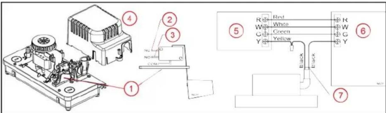
- The high water level safety switch is placed in an orientation that reverses the normal function of normally open and normally closed terminals. Pay close attention to the following instructions.
text_image
Technical diagram showing labeled components of an electronic device with wiring connections and color-coded wires- High Water Level Switch
- NC terminal. Connect here to activate an external alarm or relay.
- NO terminal. Connect here to shut off the condensing unit of the heating/cooling system.
- Motor Cover and Screw
- Thermostat
- Air Conditioner/Furnace
- Safety Switch wiring leads
There are two options for connecting the high water level switch:
- The switch is factory wired to the NO and COM terminals. This will open (break) a low voltage electrical circuit when the switch is activated by a high water level in the reservoir. This can be used to stop the condensing unit(s) of the heating/cooling system.
- Refer to the thermostat and heating/cooling unit's Operating Manual for expected switch operation and wiring connections. Connect the switch leads (7) in series with the thermostat circuit as specified in the manual.
-
The switch can be reconfigured to the NC terminal to close a low voltage circuit in the event of high water level, activating an external alarm or relay (purchased separately). Use the following procedure if an NC configuration is required:
-
Disconnect the pump from the power source.
- Remove the pump's motor cover (4).
- Support the switch and carefully change the lead from the NO terminal to the NC terminal (3).
- Re-install the motor cover.
- Connect the switch leads in series with the low voltage external component as specified in the component's manual.
Place the included "Attention Service Technician" label in a visible location.
Operation Testing
- Turn on power to the pump.
-
Test pump operating switch by gently lifting the external test/run lever to start the motor.
-
Ensure the test lever has returned to its resting position after testing.
- If the pump is located against the furnace or other vertical surface on the test switch side,
also verify the test lever is not hung up on the vertical surface preventing the pump from turning off.
text_image
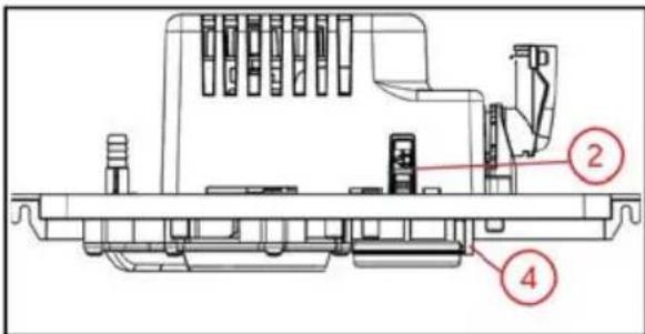
Technical diagram of a mechanical assembly with numbered components labeled 2 and 4- Disconnect the pump from the power source.
-
Test the high water level safety switch:
-
Remove the four tank cover screws to lift the cover from the tank.
- Raise the high water level switch float.
- The switch should activate before the float contacts the tank cover.
- If wired to NO terminal, air handling device should shut down when float is raised.
- If wired to NC terminal, external component (alarm or relay) should activate when float is raised.
MAINTENANCE
CAUTION
Risk of bodily injury or property damage.
- Do not allow the tank to overflow during this maintenance.
- Inspect and test the condensate removal system condition and operation every 6 months (more frequently in heavy-use applications).
To inspect and clean the tank and other components, follow these steps:
- Disconnect the pump from the power source.
-
Remove tank cover assembly from the tank.
-
Remove four screws that secure the cover assembly.
-
Carefully lift the cover assembly from the tank and hold level.
-
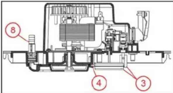
Be sure the floats move freely. Clean as necessary.
text_image
8 4 3- Remove the volute and check for obstructions. Clean as necessary.
- Clean the tank with warm water and mild soap.
- Flush tank with fresh water. This helps to ensure that residual condensate does not create localized pockets of acid that could cause pitting.
- Check inlet and outlet piping. Clean as necessary. Be sure there are no kinks in the line that would inhibit flow.
- Twist to unlock and remove the check valve and backwash the discharge port into the volute. Do this over a sink.
- Be sure check valve locks into place with an audible click when reinstalling.
- Replace the tank cover assembly.
- Test operation of the system.
Troubleshooting
| Problem Probable Causes Corrective Action | ||
| Pump does not start when tank is full of condensate water. | Pump is not connected to electrical power. | Connect pump to a dedicated GFCI circuit. |
| Circuit breaker off or fuse removed. | Turn on circuit breaker or replace fuse. | |
| Accumulation of debris or build-up on float. | Clean float; a dirty float could be too heavy to operate correctly. | |
| Float movement obstruction. | Remove the tank. Check float movement path. Remove any debris or obstruction. | |
| Defective switch. Replace pump. | ||
| Defective motor. Replace pump. | ||
| Condensate is over-flowing from the tank. | Pump is not connected to electrical power. | Connect pump to a dedicated GFCI circuit. |
| Liquid inflow matches or exceeds pump output capacity. | Larger pump required.The high level switch should shut off the A/C unit or signal an alarm in this condition if connected in the circuit correctly. Check to ensure that the pump high level switch is connected to the A/C unit (or alarm circuit), and that the leads are connected to the correct switch terminals for the application. Refer to “High Water Level Switch Connection” on page 5. | |
| Pump is not level. | Check to ensure that the pump is level. If the pump is not level, it may not activate, causing water to overflow from the tank. Place unit on a flat and level surface. | |
| Accumulation of debris or build-up on float. | Clean float. A dirty float could be too heavy to operate correctly. | |
| Check valve stuck or plugged Remove check valve and inspect for proper operation. | ||
| Outlet flow is blocked. | Check outlet tubing to ensure that it is not kinked or blocked. Clear blocked tubing of slime and debris. Clean inlet and outlet piping. | |
| Pump impeller is not turning. Clear any blockage in the impeller housing. | ||
| Defective switch. Replace pump. | ||
| Defective motor. Replace pump. | ||
| Pump will not shut off. | Float movement obstruction. | Remove the tank. Check float movement path. Remove any debris or obstruction. |
| Liquid inflow matches or exceeds pump output capacity. | Larger pump required.The high level switch should shut off the A/C unit or signal an alarm in this condition if connected in the circuit correctly. Check to ensure that the pump high level switch is connected to the A/C unit (or alarm circuit), and that the leads are connected to the correct switch terminals for the application. Refer to “High Water Level Switch Connection” on page 5. | |
| Defective switch. Replace pump. | ||
| Pump runs but does not discharge liquid. | Check valve stuck or plugged. Remove check valve and inspect for proper operation. | |
| Lift too high for pump. Check rated pump performance. | ||
| Inlet to impeller plugged. Pull pump and clean. | ||
| Outlet flow is obstructed. | Check outlet tubing to ensure that it is not kinked or blocked. Clear blocked tubing of slime and debris. Clean inlet and outlet piping. | |
| Pump does not deliver rated capacity. | Check valve stuck or plugged. Remove check valve and inspect for proper operation. | |
| Lift too high for pump. Check rated pump performance. | ||
| Low voltage, speed too slow. Check that supply voltage matches nameplate rating. | ||
| Impeller or discharge pipe is clogged. | Pull pump and clean. Check pipe for scale or corrosion. | |
| Pump cycles continually. | Check valve leaking. Remove check valve and inspect for proper operation. | |
Replacement Parts
Part Number Description
305627002 3/8" Hose Barb Check Valve Assembly
305627003 1/4"-18 NPT Check Valve Assembly
VCCA-20-P bomba de condensado para applications de plénum
La bomba VCCA-20-P está diseñada para ser utilizada en aplicaciones plenum y cumple con la norma UL UL2043, "Fire Test for Heat and Visible Smoke Release for Discrete Products and Their Accessories Installed in Air-handling Spaces."