
S19274E - Eye wash Bradley - Free user manual and instructions
Find the device manual for free S19274E Bradley in PDF.


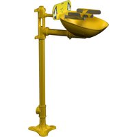
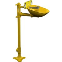
| Product Type | Eyewash/face wash activated by swing arm |
| Brand | Bradley |
| Model | S19274E |
| Compliance Standards | ANSI Z358.1 |
| Water Supply | Tepid water supply (15.6 °C to 37.8 °C) |
| Minimum Flow Pressure | 30 PSI (0.21 MPa) |
| Height of Spray Heads | Minimum 83 cm, maximum 115 cm from floor |
| Minimum Distance from Obstruction | 15 cm |
| Inlet Connection | 12" NPT (male thread) |
| Main Functions | Emergency eye and face rinsing |
| Activation | By swing arm (right-hand standard, field-convertible to left-hand) |
| Weekly Maintenance | Activate to verify flow and flush sediment |
| Monthly Maintenance | Visual inspection and functional test |
| Cleaning | Avoid organic solvents, alcohol and hydrocarbons; rinse with water |
| Replacement Parts | Available (see parts list in manual) |
| Repairability | Valve not individually replaceable; unit must be replaced |
| Warranty | See website www.bradleycorp.com |
Frequently Asked Questions - S19274E Bradley
User questions about S19274E Bradley
0 question about this device. Answer the ones you know or ask your own.
Ask a new question about this device
Download the instructions for your Eye wash in PDF format for free! Find your manual S19274E - Bradley and take your electronic device back in hand. On this page are published all the documents necessary for the use of your device. S19274E by Bradley.
USER MANUAL S19274E Bradley
Swing-Activated Eyewash and Eye/Face Wash
Pre-Installation Information 3
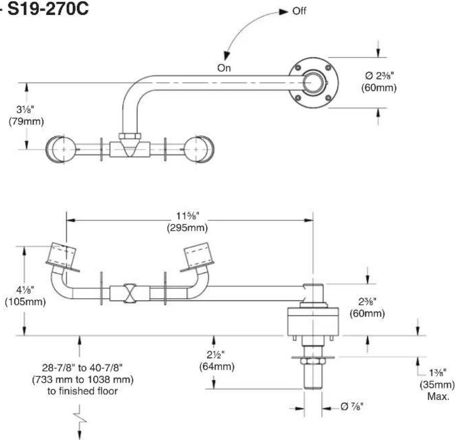
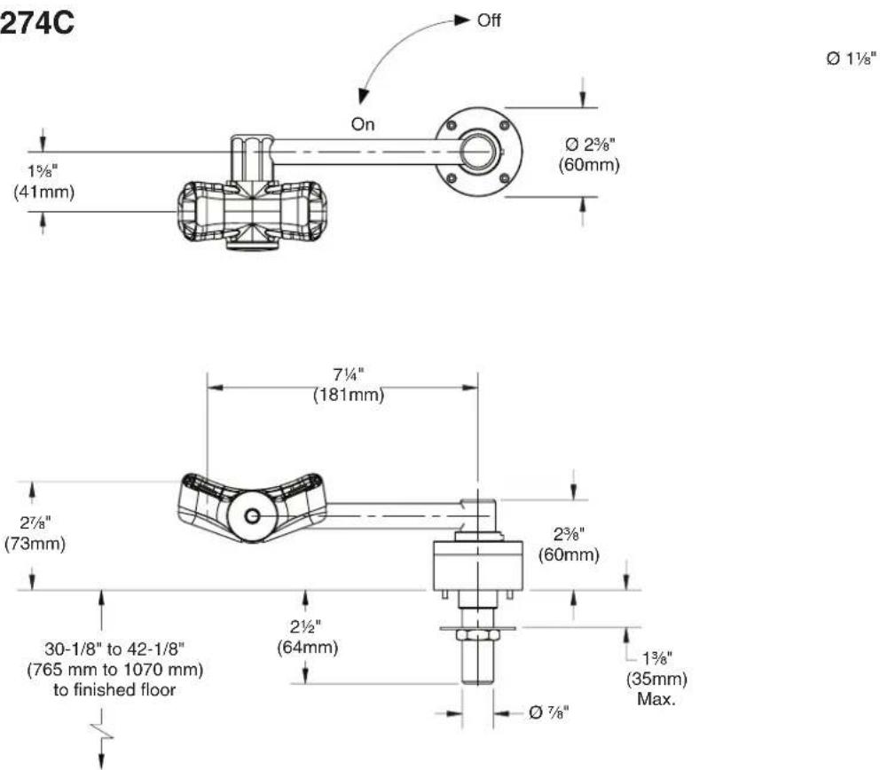
S19-270C, S19274C Dimensions 4
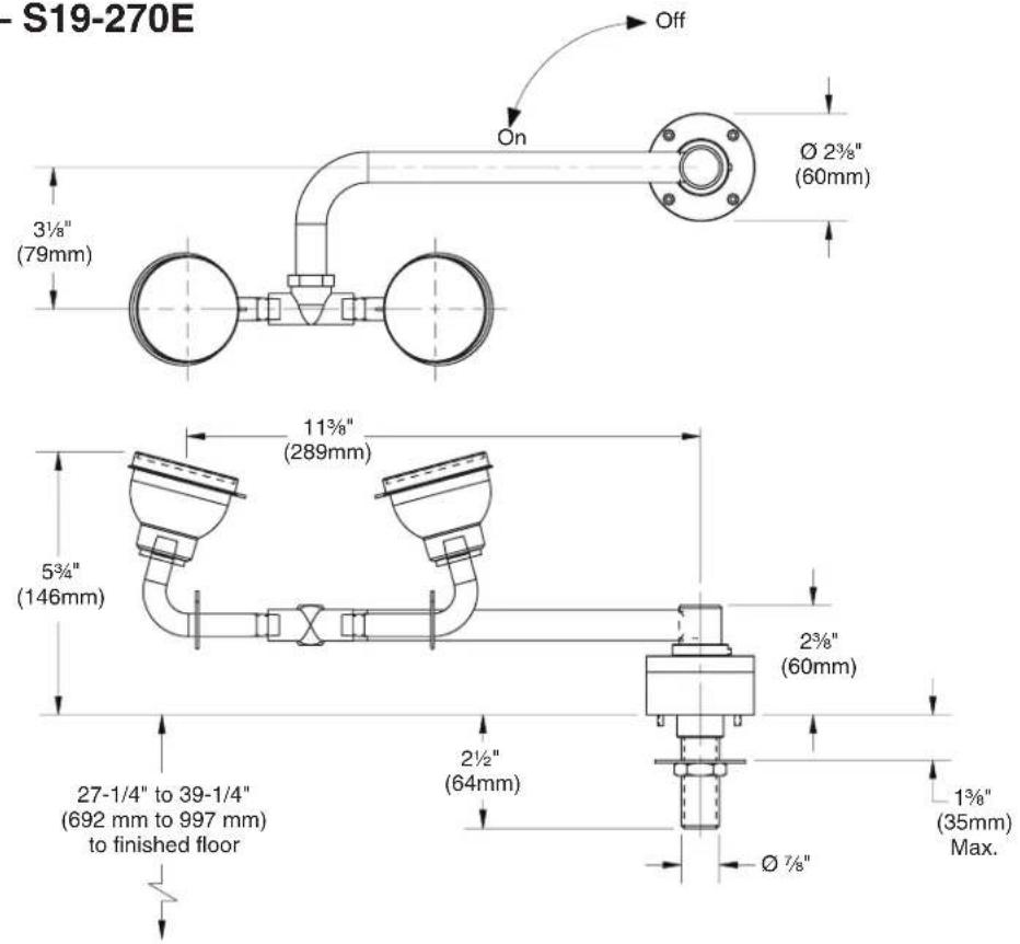
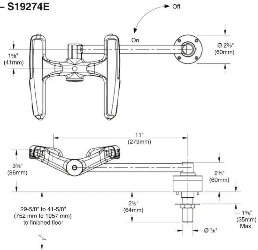
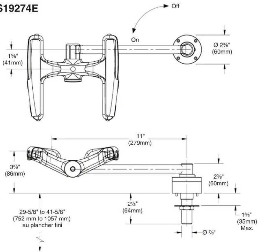
S19-270E, S19274E Dimensions 5
Installation 6-7
Installation Left-Hand Units 8–9
S19-270C Assembly of Components and Parts List 10
S19274C Assembly of Components and Parts List 11
S19-270E Assembly of Components and Parts List 12
S19274E Assembly of Components and Parts List.... 13
Table des matières
The installation and location of all Safety drench showers, eye and eye/face washes must comply with the requirements of ANSI Z358.1.
Emergency equipment must be supplied with tepid water (60-100°F/ 15.6-37.8°C). Any prolonged exposure to near freezing water affects the body's ability to maintain body temperature, increasing the risk of hypothermia.
Flush the water supply lines before beginning installation and after installation is complete. Test the unit for leaks and adequate water flow. Main water supply to the eyewash should be “ON” at all times. Provisions shall be made to prevent unauthorized shutoff.
The ANSI Z358.1 standard requires an uninterrupted supply of flushing fluid. Bradley plumbed emergency fixtures require a minimum of 30 PSI (0.21 MPa) flowing pressure. Flushing fluid should be tepid per ANSI Z358.1.
Weekly activation must be conducted on all plumbed emergency equipment to ensure a suitable flushing fluid supply is present and any sediment build-up in the supply line is cleared. Emergency Equipment should be inspected monthly to address any maintenance issues ensuring the equipment is in good operating condition and that there are no signs of wear.
Workers who may come in contact with potentially hazardous materials should be trained regarding the placement and proper operation of emergency equipment per ANSI Z358.1.
NOTICE
Before installing this product ensure that there are adequate clearances around the product and activation of the product does not interfere with other products or obstructions
For classic eye/face wash units, avoid cleaners containing organic solvents, alcohols, and hydrocarbons. Rinse with water after cleaning.
IMPORTANT
Read this installation manual completely to ensure proper installation, then file it with the owner or maintenance department. Compliance and conformity to drain requirements and other local codes/ordinances is the responsibility of the installer.
Separate parts from packaging and make sure all parts are accounted for before discarding any packaging material. If any parts are missing, do not begin installation until you obtain the missing parts.
For questions regarding the operation or installation of this product, visit bradleycorp.com or call 800.BRADLEY (800.272.3539).
Product warranties may also be found under "Products" on our web site at bradleycorp.com.
Supplies Required:
- Piping to 12 " NPT water supply inlet on unit
- Pipe sealant
• Inlet strainer (recommended)
• Sign-mounting hardware

Local codes may require the installation of a backflow prevention valve to complete proper installation. Compliance with local codes is the responsibility of the installer. Valve must be tested annually to verify that it is functioning properly. Backflow prevention valves are not included with the fixture and may be supplied by the contractor or purchased from Bradley Corporation.
Dimensions — S19-270C
Dimensions — S19274C
Dimensions — S19-270E
Dimensions — S19274E
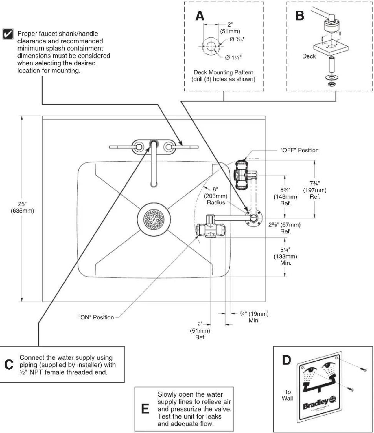
Installation — Eyewash
Halo eyewash right-hand unit is shown on a sample 25" deck. Other units are similar. For classic eyewash installation, refer to the dimensions on page 4 to determine optimal mounting position. Refer to page 8 for left-hand units.
√ Minimum dimensions necessary to contain splashing from Halo units are shown.
√ Apply pipe sealant (supplied by installer) to all male-threaded pipe joints. The top of the eyewash heads should be positioned a minimum of 33" and a maximum of 45" from the floor and 6" from the nearest obstruction.
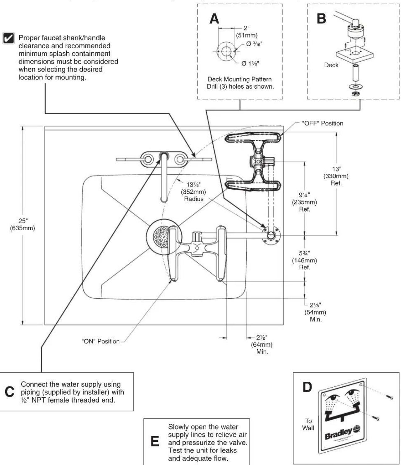
Installation — Eye/Face Wash
Halo eye/face wash right-hand unit is shown on a sample 25" deck. Other units are similar. For classic eye/face wash installation, refer to the dimensions on page 5 to determine optimal mounting position. Refer to page 8 for left-hand units.
√ Minimum dimensions necessary to contain splashing from Halo units are shown.
Apply pipe sealant (supplied by installer) to all male-threaded pipe joints. The top of the eyewash heads should be positioned a minimum of 33" (838mm) and a maximum of 45" (1143mm) from the floor and 6" (152mm) from the nearest obstruction.
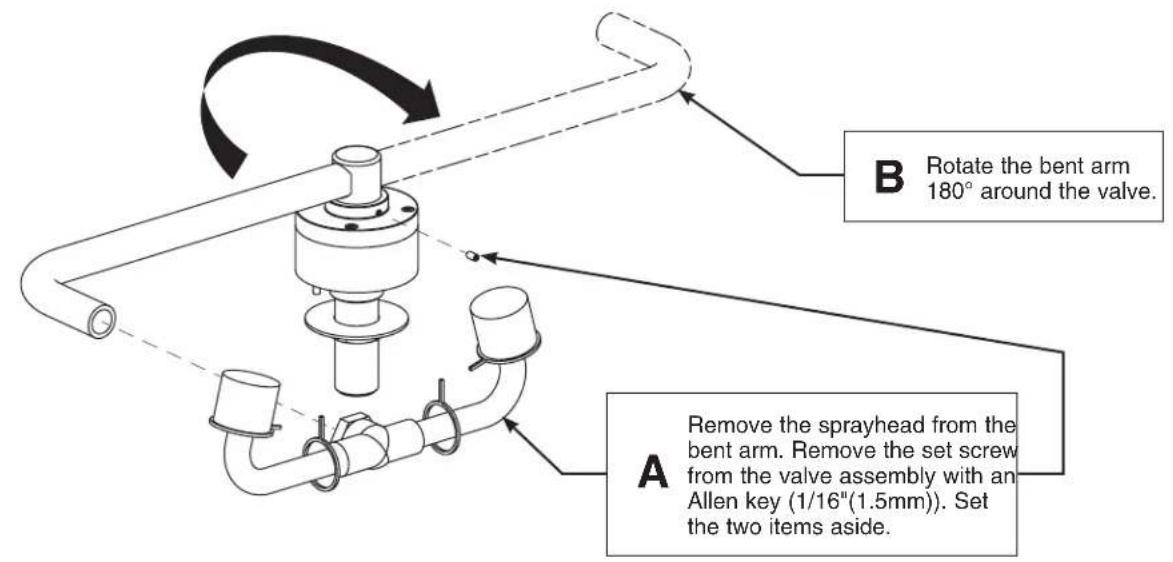
Installation — Left-Hand Units (Classic)

Classic eyewash unit is shown. Classic eye/face wash unit is similar.

Apply pipe sealant (supplied by installer) to all male-threaded pipe joints.
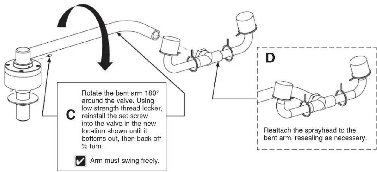

Mount the unit onto the deck. Refer to the instructions on page 6 for eyewash units or page 7 for eye/face wash units.

The left-hand unit must be installed on the left side of the deck.

Slowly open the water supply lines to relieve air and pressurize the valve. Test the unit for leaks and adequate flow.
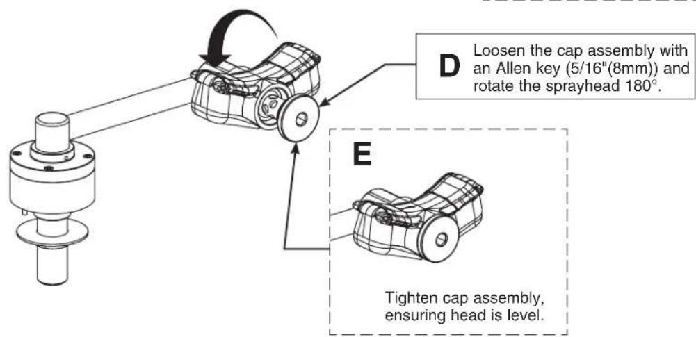
Installation — Left-Hand Units (Halo)

Halo eyewash unit is shown. Halo eye/face wash unit is similar.

Apply pipe sealant (supplied by installer) to all male-threaded pipe joints.
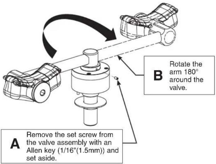
C
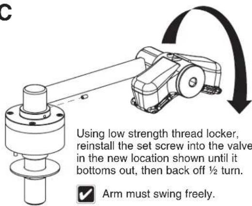
Rotate the head and body 180° around the arm.

Mount the unit onto the deck. Refer to the instructions on page 6 for eyewash units or page 7 for eye/face wash units.

The left-hand unit must be installed on the left side of the deck.

Slowly open the water supply lines to relieve air and pressurize the valve. Test the unit for leaks and adequate flow.
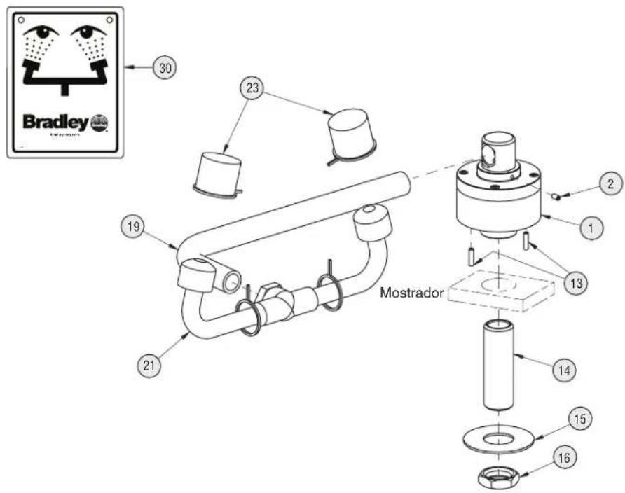
Assembly of Components and Parts List — S19-270C

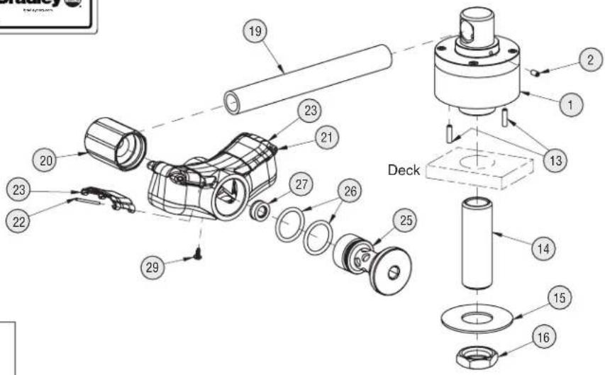
Right-hand swivel version is shown in the "ON" position.
| Item | Part No. | Qty | Description |
| 1 | N/A | 1 | Valve not available for service; must replace complete fixture. |
| 2 | 160-473 | 2 | Screw, Set |
| 13 | 160-474 | 2 | Screw, Set |
| 14 | 113-514 | 1 | Shank, 1⁄2" x 21⁄2" |
| 15 | 142-002CB | 1 | Washer, Flat 7⁄8" x 2" |
| Item | Part No. | Qty | Description |
| 16 | 110-115 | 1 | Nut, Brass 1/2"-14 NPSM |
| 19 | 113-1032 | 1 | Pipe, Bent Plated |
| 21 | S05-092 | 1 | Eyewash Yoke 90° |
| 23 | 107-371 | 2 | Tethered Dust Cover |
| 30 | 114-051 | 1 | Safety Sign |
| 31 | 204-421 | 1 | Emergency Inspection Tag |
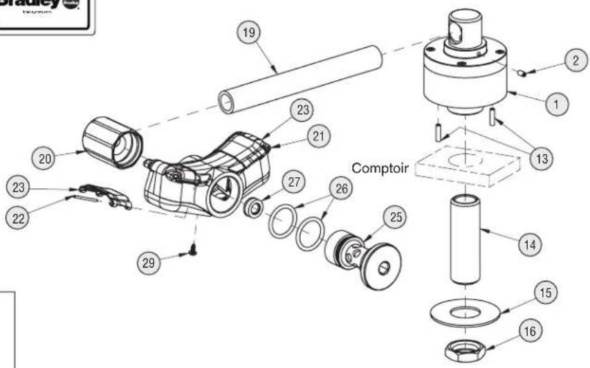
Assembly of Components and Parts List — S19274C

Right-hand swivel version is shown in the "ON" position.
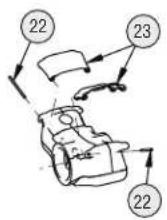
Eyewash Cover Prepack S45-2675 includes items 22 and 23
| Item | Part No. | Qty | Description |
| 1 | N/A | 1 | Valve not available for service; must replace complete fixture. |
| 2 | 160-473 | 2 | Screw, Set |
| 13 | 160-474 | 2 | Screw, Set |
| 14 | 113-514 | 1 | Shank, 1⁄2" x 21⁄2" |
| 15 | 142-002CB | 1 | Washer, Flat 7⁄8" x 2" |
| 16 | 110-115 | 1 | Nut, Brass 1⁄2"-14 NPSM |
| 19 | 113-1236 | 1 | Pipe, 3⁄8" x 51⁄2" Chrome Red Brass |
| 20 | 171-005 | 1 | Body, Mount, Short 3⁄8" NPT |
| 21 | S05-190 | 1 | Sprayhead Ass'y Eyewash (includes) |
| Item | Part No. | Qty | Description |
| 22 | in service kit | 2 | Pivot Pin |
| 23 | in service kit | 2 | Flip Cover, Eyewash |
| 25 | 115-169 | 1 | Cap, Short |
| 26 | 125-157 | 2 | O-Ring |
| 27 | 125-175 | 1 | Flow Control |
| 29 | 160-500 | 1 | Screw, Weep |
| 30 | 114-051 | 1 | Safety Sign |
| 31 | 204-421 | 1 | Emergency Inspection Tag |
Assembly of Components and Parts List — S19-270E

Right-hand swivel version is shown in the "ON" position.

| Item | Part No. | Qty | Description |
| 1 | N/A | 1 | Valve not available for service; must replace complete fixture. |
| 2 | 160-473 | 2 | Screw, Set |
| 13 | 160-474 | 2 | Screw, Set |
| 14 | 113-514 | 1 | Shank, 1⁄2" x 21⁄2" |
| 15 | 142-002CB | 1 | Washer, Flat 7⁄8" x 2" |
| 16 | 110-115 | 1 | Nut, Brass 1⁄2"-14 NPSM |
| Item | Part No. | Qty | Description |
| 19 | 113-1032 | 1 | Pipe, Bent Plated |
| 21 | S05-206 | 1 | Eye/Face Wash Assembly |
| 21A | S45-2453 | 1 | Service Kit EFW - Black Sprayheads |
| 23 | S53-063 | 2 | Tethered Dust Cover |
| 30 | 114-051 | 1 | Safety Sign |
| 31 | 204-421 | 1 | Emergency Inspection Tag |
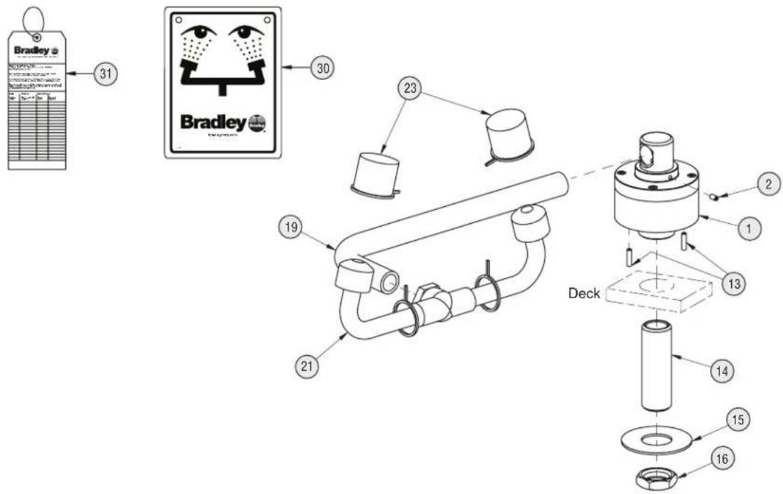
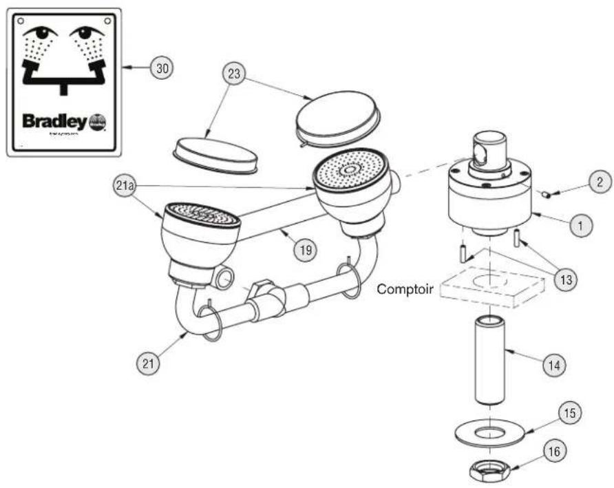
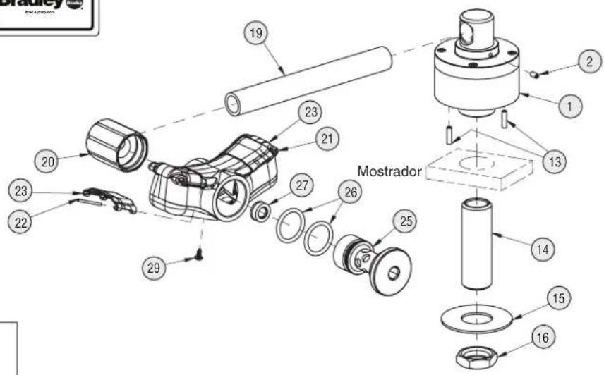
Assembly of Components and Parts List — S19274E

Right-hand swivel version is shown in the "ON" position.
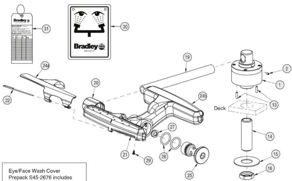
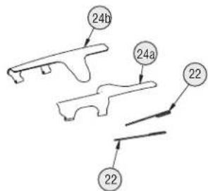
Eye/Face Wash Cover Prepack S45-2676 includes items 22, 24a and 24b
| Item | Part No. | Qty | Description |
| 1 N/A replace | 1 Valve not available to place complete fixture. | for service; must | |
| 2 160-473 2 Screw, Set | |||
| 13 | 160-474 2 | Screw, Set | |
| 14 | 113-514 1 | Shank, 12 " x 212 " | |
| 15 | 142-002CB | 1 | Washer, Flat 78 " x 2" |
| 16 | 110-115 1 | Nut, Brass 12 "-14 NPSM | |
| 19 | 113-1075 | 1 | Pipe, 38 " x 9" Chrome Red Brass |
| 20 | 171-005 | 1 | Body, Mount, Short 38 " NPT |
| 21 | S05-192 | 1 | Sprayhead Ass'y Eye/Face Wash (incl.) |
| Item | Part No. | Qty | Description |
| 22 | in service kit | 2 | Pivot Pin |
| 24a | in service kit | 1 | Flip Cover, Right |
| 24b | in service kit | 1 | Flip Cover, Left |
| 25 | 115-169 1 | Cap, Short | |
| 26 | 125-157 | 2 | O-Ring |
| 27 | 125-175 1 | Flow Control | |
| 29 | 160-500 | 1 | Screw, Weep |
| 30 | 114-051 1 | Safety S | gn |
| 31 | 204-421 | 1 | Emergency Inspection Tag |
AVERTISSEMENT
Dimensions — S19274C
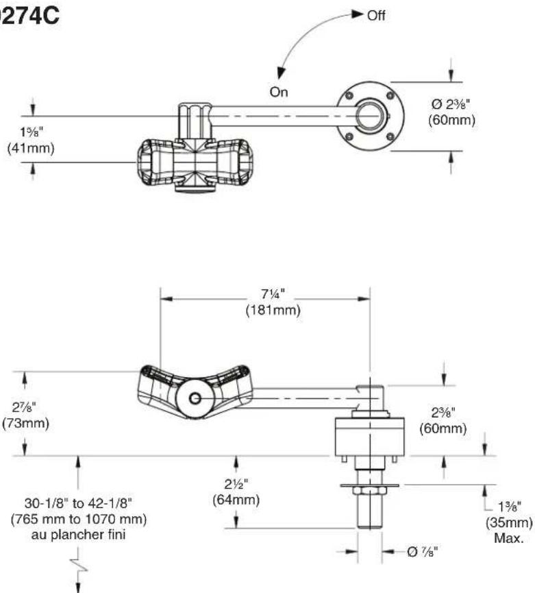
Dimensions — S19-270E
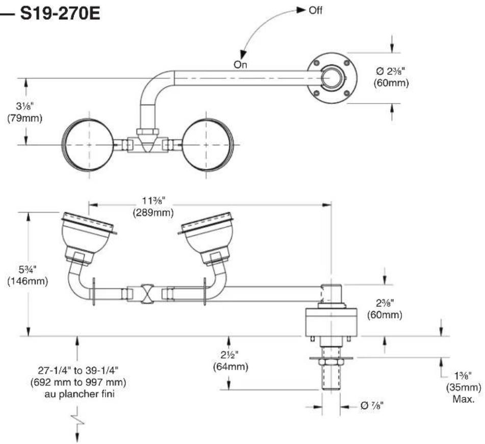
Dimensions — S19274E
Installation — Douche Oculaire




- Table des matières
- NOTICE
- IMPORTANT
- Supplies Required:
- Installation — Eyewash
- Installation — Eye/Face Wash
- Installation — Left-Hand Units (Classic)
- Installation — Left-Hand Units (Halo)
- Assembly of Components and Parts List — S19-270C
- Assembly of Components and Parts List — S19274C
- Assembly of Components and Parts List — S19-270E
- Assembly of Components and Parts List — S19274E
- AVERTISSEMENT
- Installation — Douche Oculaire
Brand : Bradley
Model : S19274E
Category : Eye wash