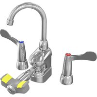
S19-500 - Sanitary faucets Bradley - Free user manual and instructions
Find the device manual for free S19-500 Bradley in PDF.


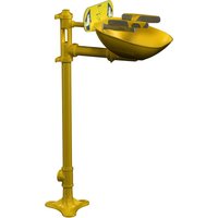
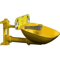
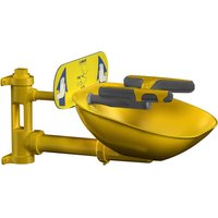
| Product type | Halo Pivoting Eye Wash Faucet Mount |
| Brand | Bradley |
| Model | S19-500 (and variants S19-505, S19-500T, S19-500M, S19-500W) |
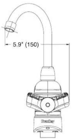
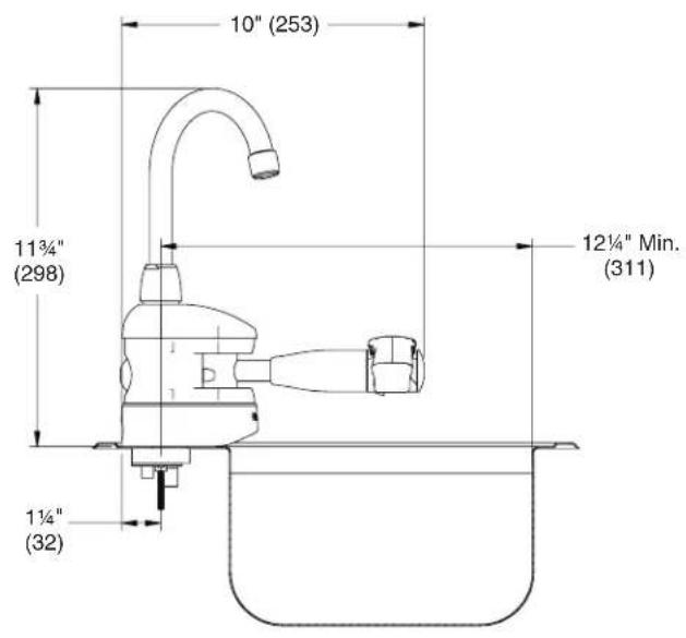
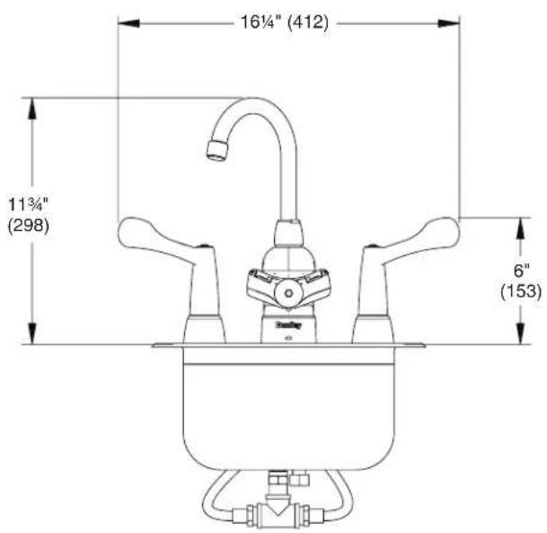
| Dimensions (W x D x H) | 150 x 298 x 253 mm (5.9 x 11.75 x 10 in) |
| Flow pressure | 2.0 to 6.1 bar (30 to 90 psi) |
| Max static pressure | 8.6 bar (125 psi) |
| Water temperature | 16 to 38 °C (60 to 100 °F) |
| Water supply | Clean, tepid potable water, uninterrupted supply |
| Compliance standard | ANSI/ISEA Z358.1 |
| Main functions | Pivotable eye wash, adjustable faucet spout, integrated mixing valve (depending on variant) |
| Installation | On sink (not included), 38 mm (1½ in) hole, by a qualified plumber |
| Maintenance | Weekly inspection, check flow and temperature |
| Spare parts | Available (see parts list, e.g. valve cartridges, shower heads, hoses) |
| Warranty | See bradleycorp.com |
| Repairability | Spare parts and technical support available |
Frequently Asked Questions - S19-500 Bradley
User questions about S19-500 Bradley
0 question about this device. Answer the ones you know or ask your own.
Ask a new question about this device
Download the instructions for your Sanitary faucets in PDF format for free! Find your manual S19-500 - Bradley and take your electronic device back in hand. On this page are published all the documents necessary for the use of your device. S19-500 by Bradley.
USER MANUAL S19-500 Bradley
natural_image
Line drawing of a medical or laboratory device with a curved handle and labeled component (no text or symbols present)Installation
S19-500 Series & S19-505 Series
Halo™ Swing-Activated Faucet Eyewash
Read the instructions in this manual before beginning installation. Save these instructions and refer to them for inspection, maintenance and troubleshooting information.

For questions regarding the operation, installation or maintenance of this product, visit bradleycorp.com or call 800.BRADLEY (800.272.3539).
Product warranties and parts information may also be found under "Resources" on our website at bradleycorp.com.
215-1910 Rev. D: ECO 21-05-013
© 2021 Bradley
Page 1 of 47 7/6/2021
P.O. Box 309
Menomonee Falls, WI 53052 USA
800 BRADLEY (800 272 3539)
+1 262 251 6000
bradleycorp.com

Table of Contents
Safety Information 3
Supplies Required 3
Dimensions 4-5
Installation 6-7
Install Supply Hoses 8
Install Faucet Hoses 9-11
Plumb to Mixing Valves 12-14
Change Faucet & Eyewash Direction 15
Assembly of Components 16
Parts List 17
Table des matières
To ensure proper operation:
Installation
The eyewash portion of this fixture has been designed and 3rd party tested to meet ANSI/ISEA Z358.1. The system must be tested periodically to be sure it is functioning properly to meet the standard. Please refer to the ANSI/ISEA Z358.1 standard on testing requirements.
The installation, maintenance and location of all safety fixtures must comply with the requirements of ANSI/ISEA Z358.1. Workers who may come in contact with potentially hazardous materials should be trained regarding the location and proper operation of emergency equipment per ANSI/ISEA Z358.1.
ANSI/ISEA Z358.1 requires this unit to be used with a clean, potable, uninterrupted supply of tepid water. Bradley plumbed emergency fixtures require a minimum of 30 psi flowing pressure in order to function as designed and meet the ANSI/ISEA Z358.1 standard.
Before installation make sure that this equipment will meet the requirements of the potential hazardous contaminants in your location.
Installation of this system must be completed by a qualified plumber in compliance with all national and local codes. Compliance and conformity to drain requirements and other local codes and ordinances is the responsibility of the installer.
Weekly Inspections
To ensure that the emergency eyewash fixture is ready to be used when needed, regular checks and maintenance must be conducted. Weekly inspections must be conducted on all safety equipment to make sure a suitable flushing fluid supply is present and to make sure the equipment is in good operating condition.
Water Temperature
ANSI/ISEA Z358.1 requires the eyewash to be supplied with tepid water. Suitable range is 60^ F to 100^ F ( 16^ C to 38^ C). Personal injury is possible outside this temperature range.
The faucet valves supplied with this fixture only controls the volume of the water supply of the faucet spout. Upon installation, the faucet's hot water supply temperature must be checked and adjusted at its source to ensure delivery of a safe water temperature. Water in excess of 110^ F ( 43^ C) may cause scalding.
Supplies Required
- Piping to all water supply inlets on unit
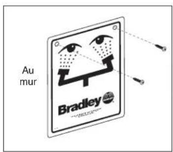
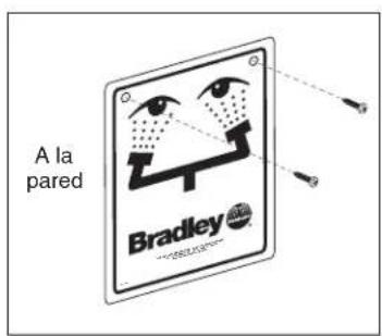
• Sign-mounting hardware
• 30 psi (2.0 bar) min/90 psi (6.1 bar) max flow pressure
• 125 psi (8.6 bar) max static pressure
Dimensions – S19-500 & S19-505
Front View
Side View
Dimensions – S19-500W & S19-505W
Front View (S19-500W shown)
Side View (S19-500W shown)

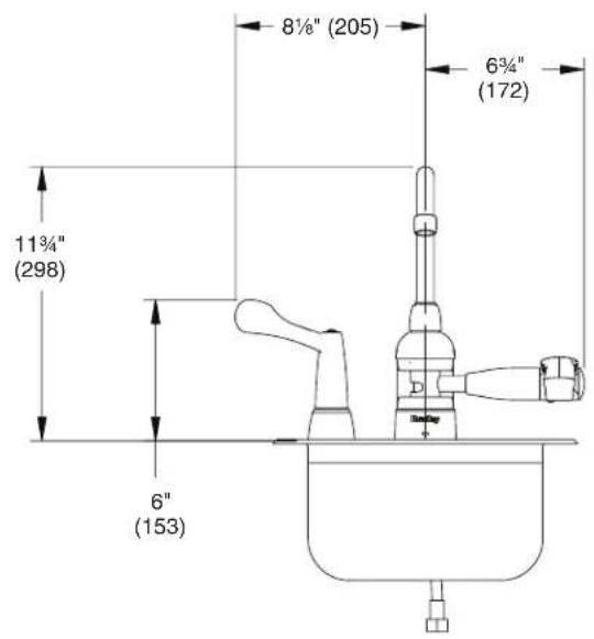
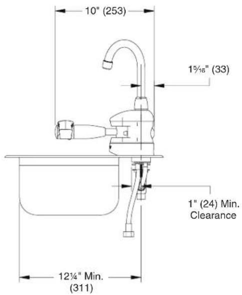
Dimensions – S19-500T & S19-505T
Front View (S19-500T shown)
Side View (S19-500T shown)
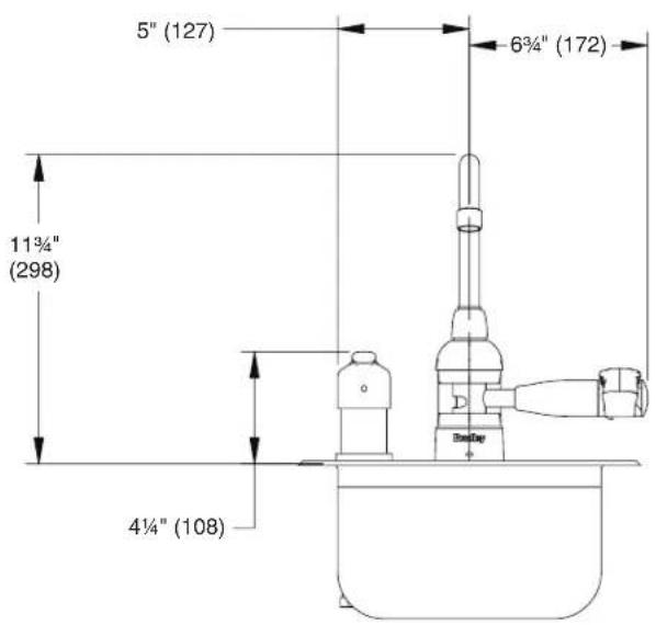
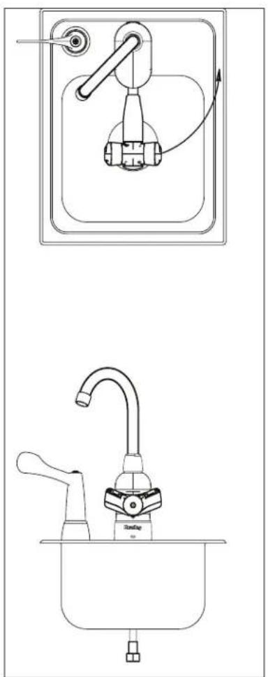
Dimensions - S19-500M & S19-505M
Front View (S19-500M shown)
Side View (S19-500M shown)

Installation

Halo eye/face wash unit is shown on a sink (not included).

The top of the eyewash heads should be positioned a minimum of 33" (838 mm) and a maximum of 45" (1143 mm) from the floor and 6" (152 mm) from the nearest obstruction.
natural_image
Technical line drawing of a kitchen sink with faucet and door handle (no text or symbols)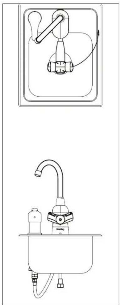
natural_image
Line drawings of a kitchen sink and a hand pump (no text or symbols)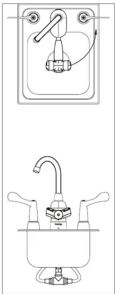
natural_image
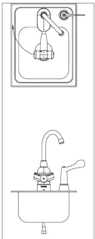
Technical line drawing of a kitchen sink with faucet and control panel (no text or symbols)S19-500T S19-500M S19-500W

Installation - cont.
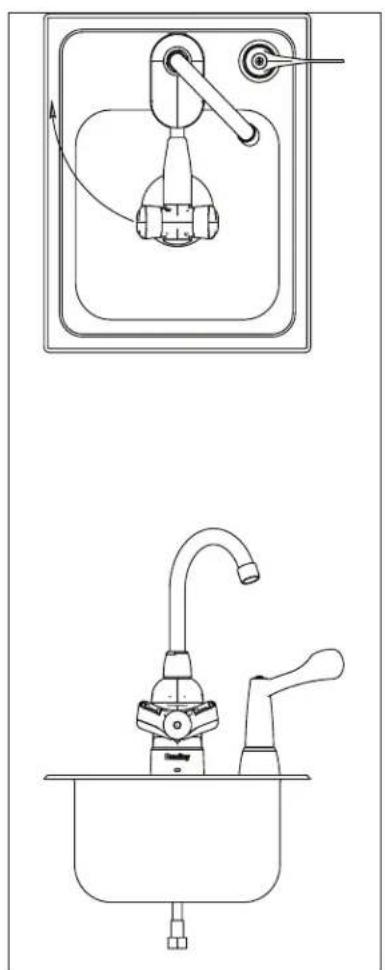
natural_image
Line drawings of a kitchen sink and faucet with handlebars (no text or symbols)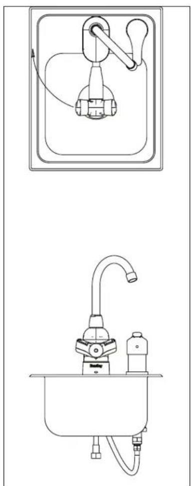
natural_image
Technical line drawings of a kitchen sink and sink with faucet and handle (no text or symbols)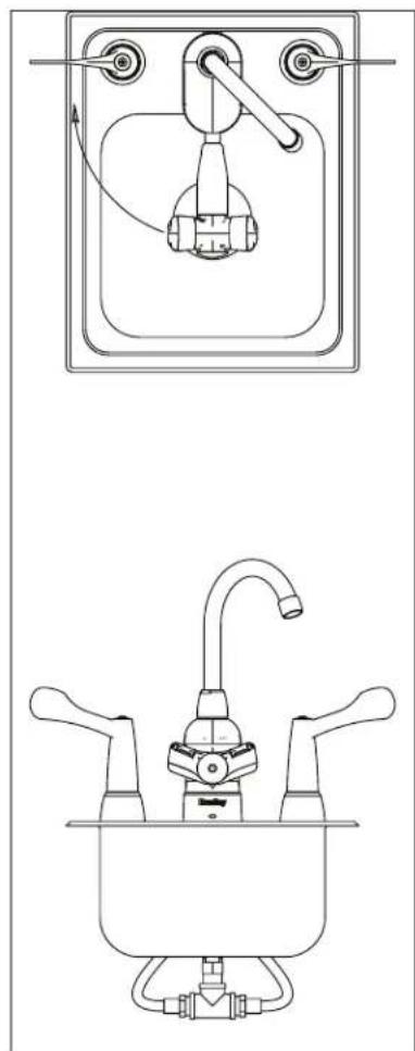
natural_image
Technical line drawing of a kitchen sink and sink with faucet (no text or symbols)S19-505T S19-505M S19-505W
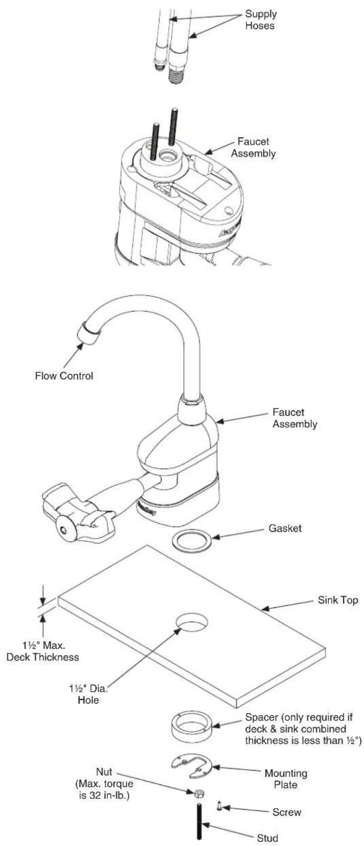
1 Install Faucet Assembly
A Install the supply hose to the bottom of the faucet assembly.
B Install the gasket to the bottom of the faucet assembly.
C Install bolt studs into the base of the unit, and then set the faucet assembly onto the sink.
D For thin sink decks, connect the mounting plate to the spacer with the provided screws, and then secure studs with the provided nuts. For thinner decks, discard the spacer. Snug tight to the sink.
E Install the desired flow control.
2a Install Faucet Hoses (S19-500T & S19-505T)

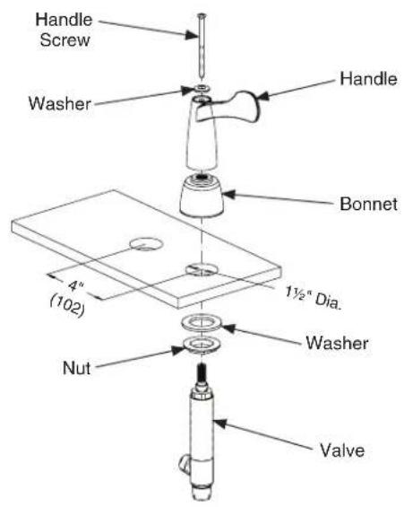
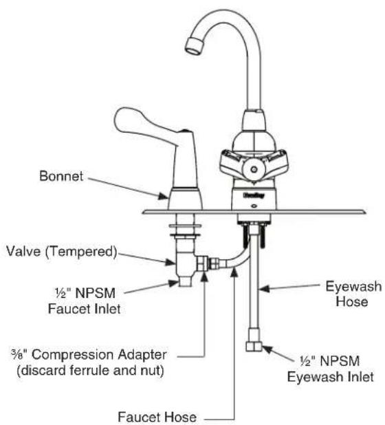
Thread the nut and washer onto the valve.

Insert the valve into the sink deck from the bottom.

Thread the bonnet onto the valve assembly from the top, and tighten the nut from the bottom.

Slide the handle onto the valve assembly. Place the washer onto the handle and install the handle screw.

Plumb the faucet hose to the side port on the valve using the provided fitting.

Plumb the eyewash hose to the eyewash supply.

Plumb the faucet supply to the bottom of the valve assembly (hose supplied by installer).
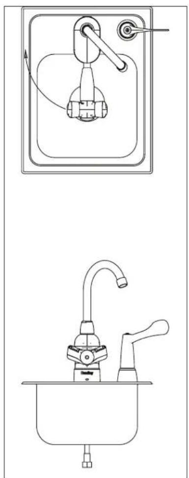
2b Install Faucet Hoses (S19-500M & S19-505M)

Set the valve body assembly in place.
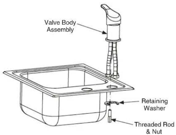

Slide the retaining washer in place.

Thread the nut onto the thread rod and tighten the nut to hold the valve assembly in place.

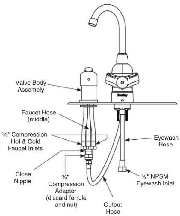
Plumb the output hose from the valve assembly to the faucet hose, using the provided nipple and fitting.

Plumb the eyewash hose to the eyewash supply, and then plumb the faucet supply to the valve assembly.
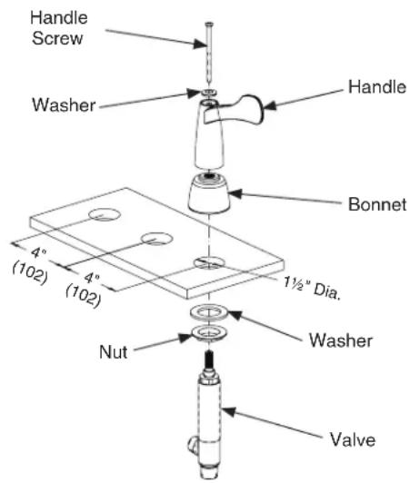
2c Install Faucet Hoses (S19-500W & S19-505W)
A Thread the nut and washer onto the valve.
B Insert the valve into the sink deck from the bottom.
C Thread the bonnet onto the valve assembly from the top, and tighten the nut from the bottom.
D Slide the handle onto the valve assembly. Place the washer onto the handle and install the handle screw.
√ Repeat Steps A–D for both handle assemblies.
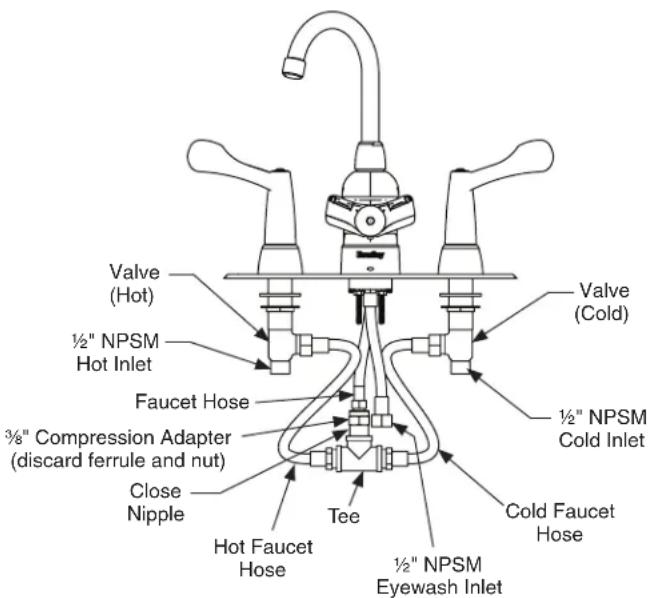
E Plumb the eyewash hose to the eyewash supply.
F Plumb the faucet hose to the tee using the provided nipple and fitting.
G Plumb the hoses from the side ports on each valve to the provided tee.
H Plumb the faucet supply to the bottom of the valve assembly (hose supplied by installer).
3a Plumb to S19-2010 Mixing Valve (S19-500T & S19-505T)
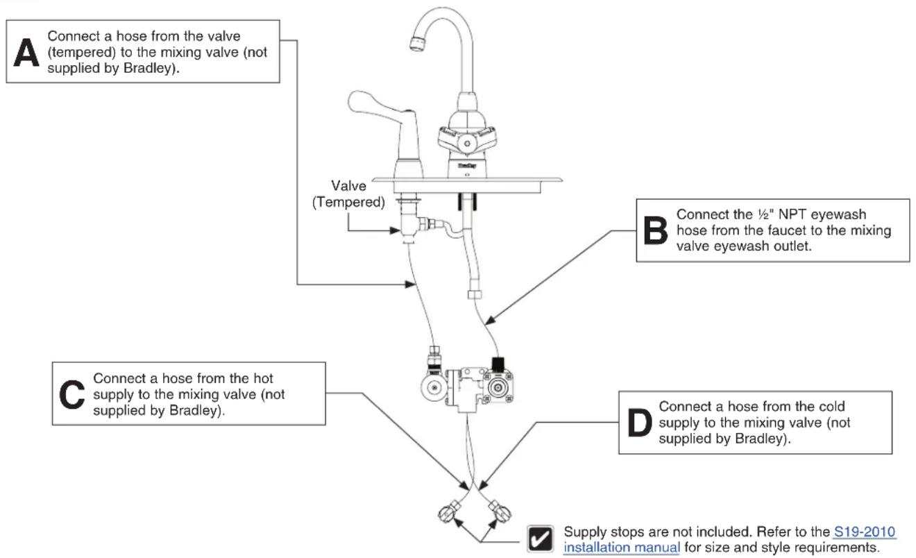
flowchart
graph TD
    A["Connect a hose from the valve (tempered) to the mixing valve (not supplied by Bradley)."] --> B["Valve (Tempered)"]
    B --> C["Connect the ½" NPT eyewash hose from the faucet to the mixing valve eyewash outlet."]
    C --> D["Connect a hose from the hot supply to the mixing valve (not supplied by Bradley)."]
    D --> E["Supply stops are not included. Refer to the S19-2010 installation manual for size and style requirements."]
    B --> F["Connect a hose from the cold supply to the mixing valve (not supplied by Bradley)."]
    F --> G["Supply stops are not included. Refer to the S19-2010 installation manual for size and style requirements."]
3b Plumb to S19-2000 Mixing Valve (S19-500M & S19-505M)
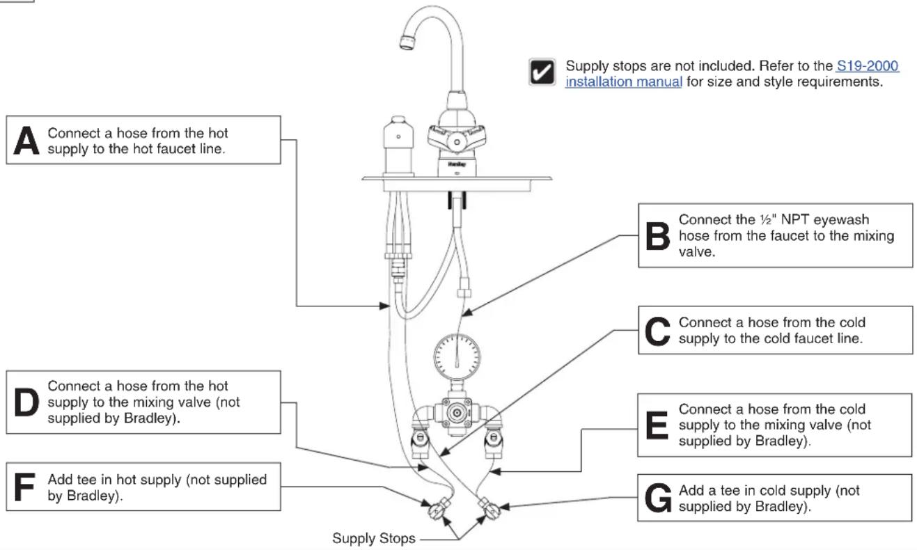
flowchart
graph TD
    A["Connect a hose from the hot supply to the hot faucet line."] --> B["Connect the ½" NPT eyewash hose from the faucet to the mixing valve."]
    B --> C["Connect a hose from the cold supply to the cold faucet line."]
    C --> D["Connect a hose from the cold supply to the mixing valve (not supplied by Bradley)."]
    D --> E["Add a tee in cold supply (not supplied by Bradley)."]
    E --> F["Add tee in hot supply (not supplied by Bradley)."]
    F --> G["Supply Stops"]
3c Plumb to S19-2010 Mixing Valve (S19-500M & S19-505M)
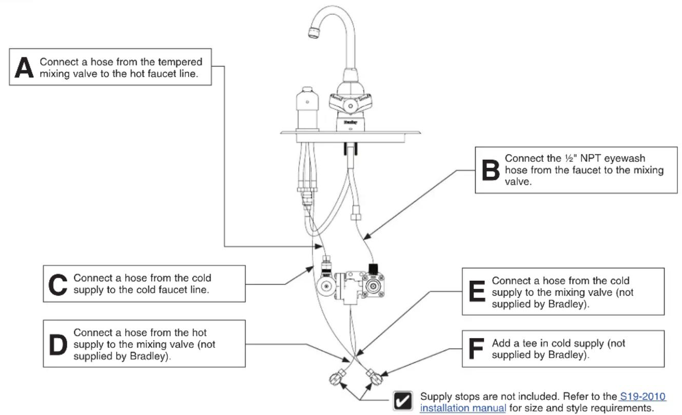
flowchart
graph TD
    A["Connect a hose from the tempered mixing valve to the hot faucet line."] --> B["Connect the ½" NPT eyewash hose from the faucet to the mixing valve."]
    C["Connect a hose from the cold supply to the cold faucet line."] --> D["Connect a hose from the hot supply to the mixing valve (not supplied by Bradley)."]
    E["Connect a hose from the cold supply to the mixing valve (not supplied by Bradley)."] --> F["Add a tee in cold supply (not supplied by Bradley)."]
    G["Supply stops are not included. Refer to the S19-2010 installation manual for size and style requirements."] --> H["End"]
3d Plumb to S19-2000 Mixing Valve (S19-500W & S19-505W)
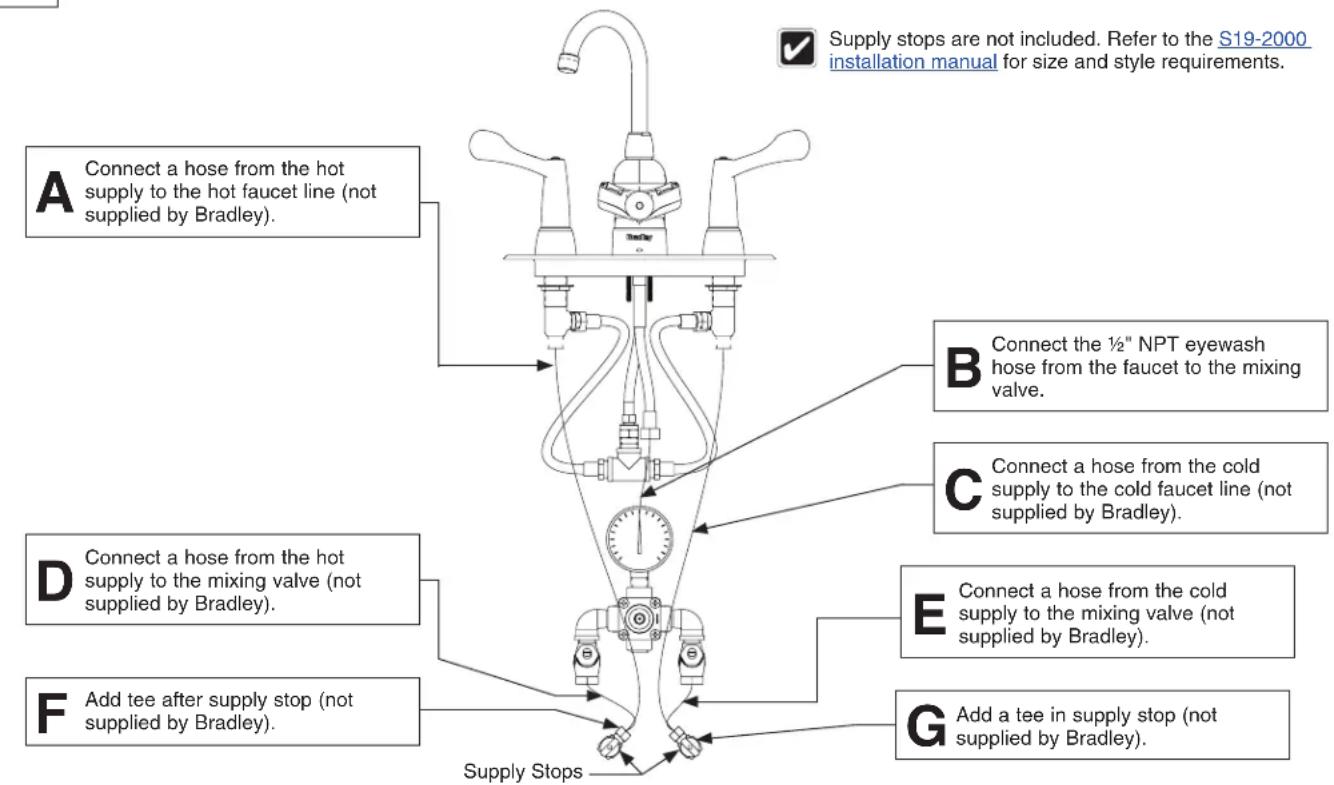
3e Plumb to S19-2010 Mixing Valve (S19-500W & S19-505W)
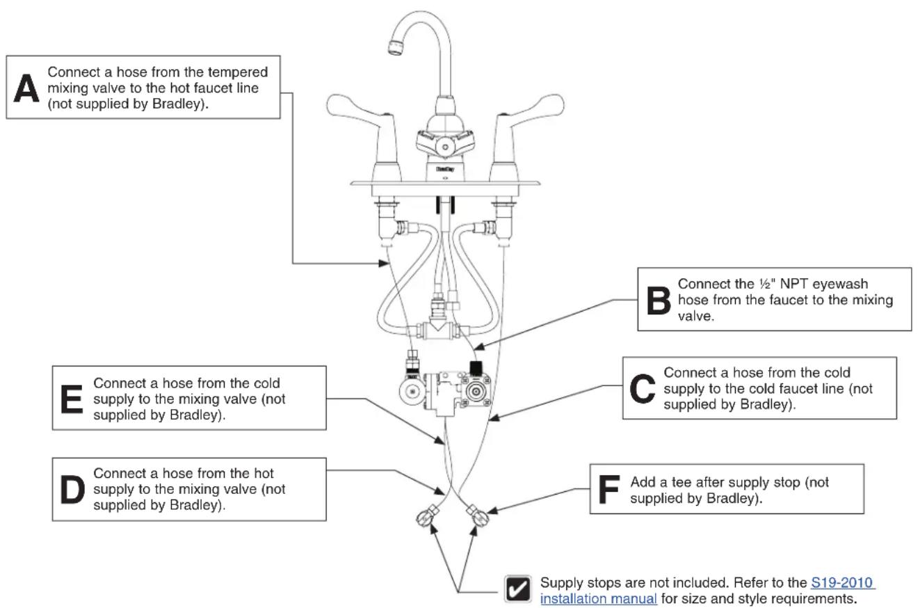
flowchart
graph TD
    A["Connect a hose from the tempered mixing valve to the hot faucet line (not supplied by Bradley)."] --> B["Connect the ½" NPT eyewash hose from the faucet to the mixing valve."]
    C["Connect a hose from the cold supply to the mixing valve (not supplied by Bradley)."] --> D["Connect a hose from the cold supply to the cold faucet line (not supplied by Bradley)."]
    E["Connect a hose from the hot supply to the mixing valve (not supplied by Bradley)."] --> F["Add a tee after supply stop (not supplied by Bradley)."]
    G["Supply stops are not included. Refer to the S19-2010 installation manual for size and style requirements."] --> H["End"]
Change Faucet & Eyewash Swing Direction

From the bottom of the unit, remove the two Phillips head screws to allow the top spout assembly and cover to slide up and be removed.
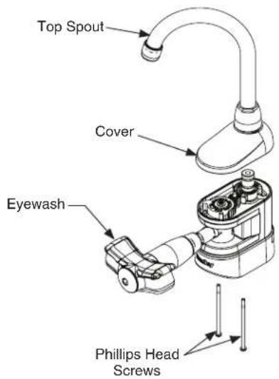

Verify the eyewash is in the On position as shown.

Remove the wave washer from on top of the rear gear. Set aside for reinstallation.

Reposition the pin at the front hole marked with the L or R. Refer to the illustration.

Slide the rear gear up and off of the post. Flip the rear gear as needed per the illustration.

Slide the rear gear back on to the post, aligning the gear teeth to fit with the small center gear. Verify the L or R on the rear gear matches the pin position used.

Test the eyewash rotation. Verify the eyewash movement is stopped by the pin in each direction. If it is not stopped, adjust the rear gear to engage with the correct teeth.

Slide the wave washer back into position on top of the rear gear.

Move the eyewash to the Off position by rotating it to the right or left side.

Reassemble the top spout assembly and cover and secure using the two Phillips screws removed in Step A.

Check the function of the unit by swinging the eyewash assembly from the On position to the Off position. Verify the faucet is free to rotate. Move the eyewash to the On position and verify the faucet swings out of the way.
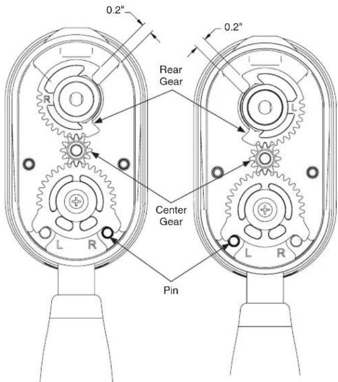
S19-500 S19-505
Assembly of Components
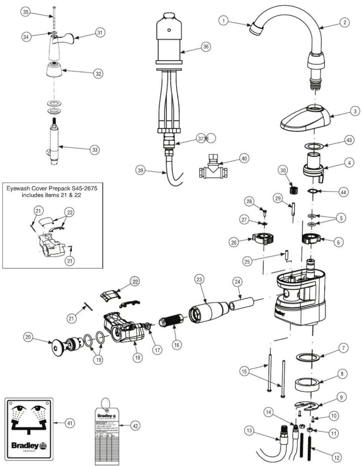
Parts List
| Item | Part No. Qty | Description | Item Part No. Qty Description | ||||
| 1 | S45-3009 | 1 | Flow Control Kit (1.5 gpm & 2.2 gpm) | 28 | 160-329 | 1 | Screw, 6-32 x 3/8 RD |
| 2 | S53-357 | 1 | Spout w/ Swivel Lock Feature | 29 | 152-073 | 1 | Quarter Groove Pin 3/16 x 1 |
| 3 | 107-675 | 1 | Cover | 30 | 143-075 | 1 | Gear - Middle |
| 4 | 118-358 | 1 | Adapter - Spout | 31 | 128-211 | 2 | Handle, S19-500W & S19-505W(S19-500T & S19-505T (Qty 1)) |
| 5 | 125-001CB | 2 | O-Ring | 32 | 121-031 | 2 | Bonnet Nut, S19-500W & S19-505(S19-500T & S19-505T (Qty 1)) |
| 6 | 143-076 | 1 | Gear - Spout | 33 | S73-060 | 1 | Valve, Faucet / Cold Water, S19-500W& S19-505T |
| 7 | 124-116 | 1 | Gasket | 33A | S73-060A | 1 | Valve Cartridge Cold - Service |
| 8 | 104-157 | 1 | Spacer - Mounting | ns | S73-061A | 1 | Valve Cartridge Hot - Service |
| 9 | 159-488 | 1 | Mounting Plate | ns | S73-061 | 1 | Valve, Faucet / Hot Water, S19-500W& S19-500T |
| 10 | 160-478 | 2 | Screw, 4-40 x 3/8 Pan | 34 | 142-157B | 1 | Washer, Lever Blue, S19-500W &S19-505W |
| 11 | 161-154 | 2 | Nut, 10-32 Hex Lock | 34 | 142-157R | 1 | Washer, Lever Red, S19-500W &S19-505W |
| 12 | 147-050 | 2 | Stud, 10-32 x 2 | 34 | 142-157W | 1 | Washer, Lever Chrome, S19-500T &S19-505T |
| 13 | 269-2789 | 1 | Hose, SS M12-1 x 1/2-14 NPSM | 35 | 160-562 | 2 | Screw, 10-24 x 3 OV, S19-500W &S19-505W (S19-500T &S19-505T (Qty 1)) |
| 14 | 269-2788 | 1 | Hose, M8-1 x 3/8 Compression | 36 | S73-062 | 1 | Valve Body Assembly, S19-500M &S19-505M |
| 15 | 160-560 | 2 | Screw, 8-32 x 3 | 36A | S73-062A | 1 | Valve Cartridge - Service |
| 16 | 173-032 | 1 | Strainer - Plastic - Slotted | 36B | S73-062B | 1 | Handle - Service |
| 17 | 125-175 | 1 | Flow Control 4.8 | 36C | S73-062C | 1 | Hose Kit (all 3) - Service |
| 18 | S05-189 | 1 | Sprayhead Assembly | 36D | S73-062D | 1 | Hardware Mounting - Service |
| 19 | 125-157 | 2 | O-Ring (-117) 0.799 ID x 0.103 W | 37 | 113-006DH | 2 | Pipe, 1/2 x Close Red Brass |
| 20 | 115-159 | 1 | Body - Cap | 38 | 269-1999 | 3 | Comp FTG 1/2 NPTF x 3/8 OD |
| 21 | 166-012 | 2 | Pin Hinge | 39 | 269-653 | 4 | Hose, Flexible 1/2 NPT 24 LG |
| 22 | 107-604 | 2 | Dust Cover, Eye Wash | 40 | 269-1150 | 1 | Tee, 1/2" |
| 23 | 171-010 | 1 | Body Mount 3/8 NPT Female | 41 | 114-051 | 1 | Eyewash Sign |
| 24 | 113-1333 | 1 | Pipe, 3/8 x 2 Chrome | 42 | 204-421 | 1 | Inspection Tag |
| 25 | 152-072 | 1 | Pin, 3/16 x 3/4 | 43 | 142-137 | 1 | Friction Washer |
| 26 | 143-074 | 1 | Gear - Large, Swivel | 44 | 142-158 | 1 | Wave Washer |
| 27 | 142-002AQ | 1 | Washer, 0.203 x 0.438 x 0.032 Flat |
Fournitures requises
natural_image
Technical line drawing of a kitchen sink with faucet and door handle (no text or symbols)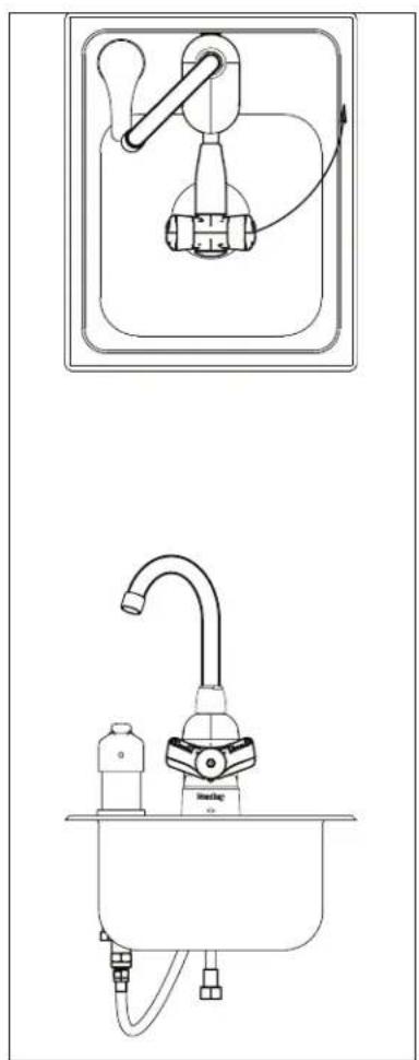
natural_image
Line drawings of a kitchen sink and faucet system (no text or symbols)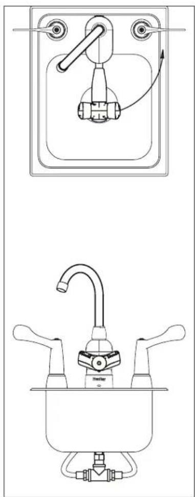
natural_image
Technical line drawing of a kitchen sink with faucet and control panel (no text or symbols)S19-500T S19-500M S19-500W
Installation – suite
natural_image
Line drawings of a kitchen sink and faucet (no text or symbols)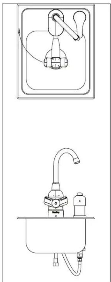
natural_image
Technical line drawings of a kitchen sink and sink with faucet and handle (no text or symbols)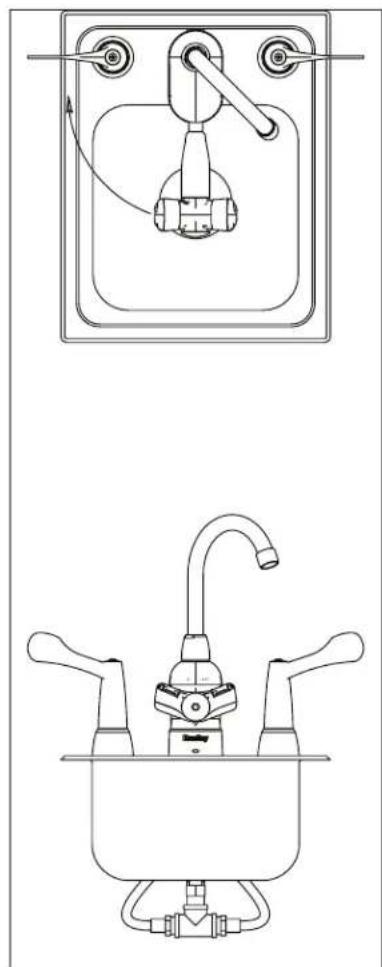
natural_image
Technical line drawing of a kitchen sink and faucet assembly (no text or symbols)S19-505T S19-505M S19-505W
B
natural_image
Technical line drawing of a kitchen sink with faucet and door handle (no text or symbols)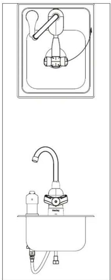
natural_image
Line drawings of a kitchen sink and a hand pump (no text or symbols)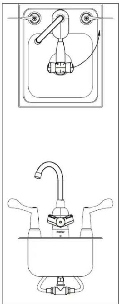
natural_image
Technical line drawing of a kitchen sink with faucet and control panel (no text or symbols)S19-500T S19-500M S19-500W
Instalación – sigue
natural_image
Line drawings of a kitchen sink and faucet (no text or symbols)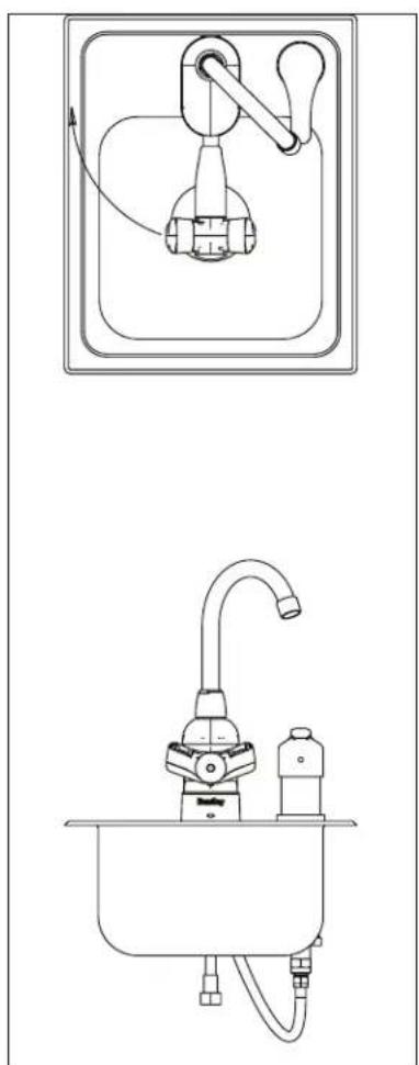
natural_image
Technical line drawings of a kitchen sink and sink with faucet and handle (no text or symbols)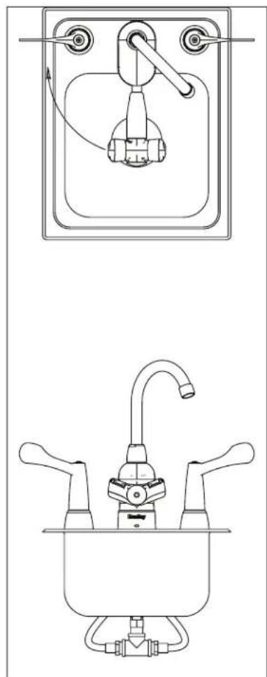
natural_image
Technical line drawing of a kitchen sink with faucet and water dispenser (no text or symbols)S19-505T S19-505M S19-505W
- Installation
- Table of Contents
- Table des matières
- To ensure proper operation:
- Weekly Inspections
- Water Temperature
- Supplies Required
- Dimensions – S19-500 & S19-505
- Dimensions – S19-500W & S19-505W
- Dimensions – S19-500T & S19-505T
- Dimensions - S19-500M & S19-505M
- Installation - cont.
- Install Faucet Assembly
- 2a Install Faucet Hoses (S19-500T & S19-505T)
- 2b Install Faucet Hoses (S19-500M & S19-505M)
- 2c Install Faucet Hoses (S19-500W & S19-505W)
- Change Faucet & Eyewash Swing Direction
- Fournitures requises
- Installation – suite
- B
- Instalación – sigue
Brand : Bradley
Model : S19-500
Category : Sanitary faucets