
Coreblade - Audio Amplifier HUGHES & KETTNER - Free user manual and instructions
Find the device manual for free Coreblade HUGHES & KETTNER in PDF.

User questions about Coreblade HUGHES & KETTNER
0 question about this device. Answer the ones you know or ask your own.
Ask a new question about this device
Download the instructions for your Audio Amplifier in PDF format for free! Find your manual Coreblade - HUGHES & KETTNER and take your electronic device back in hand. On this page are published all the documents necessary for the use of your device. Coreblade by HUGHES & KETTNER.
USER MANUAL Coreblade HUGHES & KETTNER
natural_image
Decorative ornamental emblem featuring a stylized flame or skull design surrounded by swirling vines (no text or symbols)COREBLADE
Manual 1.1
text_image
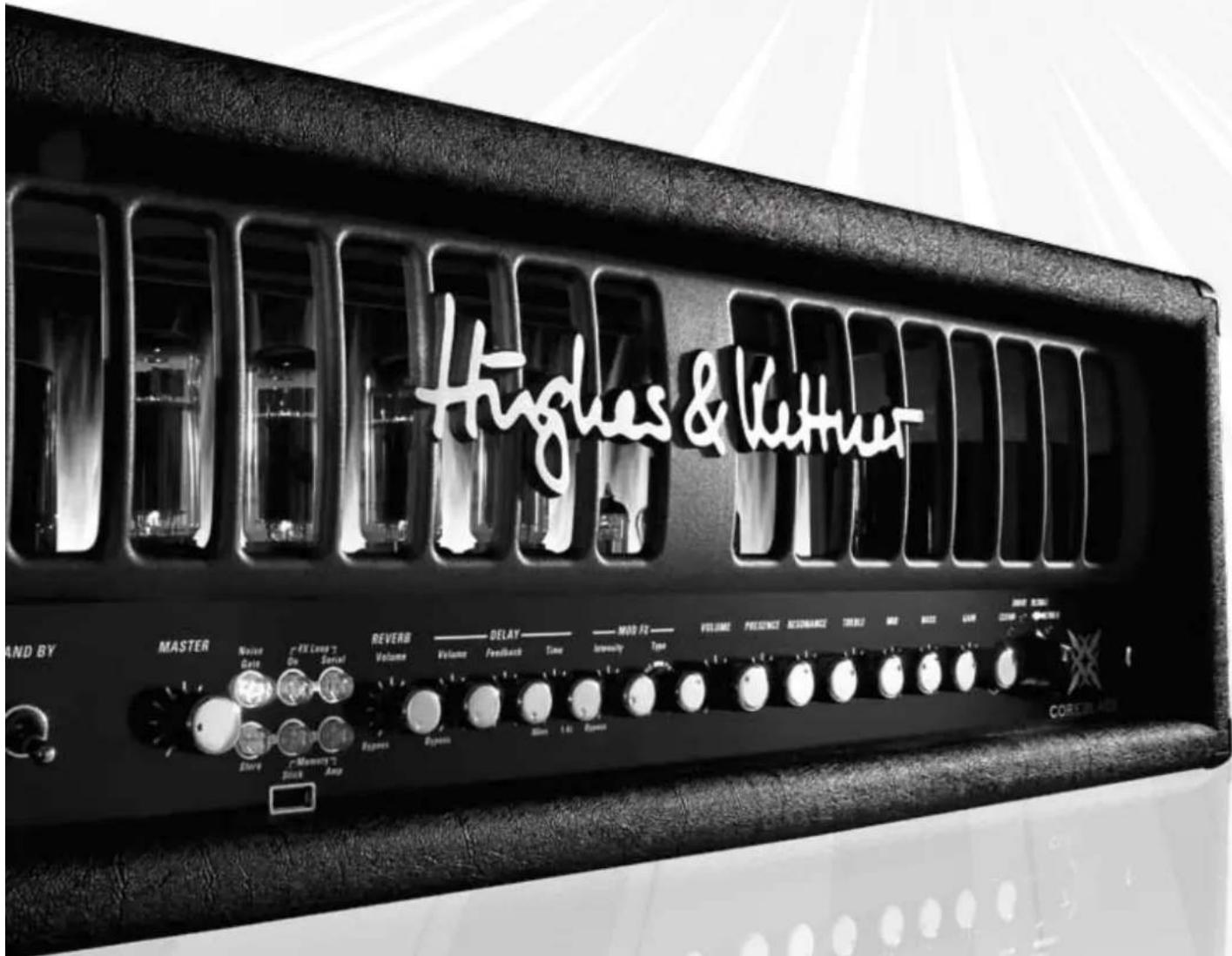
Hughes & Lettner AND BY MASTER Noise Data FX Long 7 Do Serial REVERB Volume DELAY Volume Feedback Time MOD FZ Intensity Type VOLUME PRESENCE RECOMMANCE TREN2 AND FREE CASH CURRENT CHINESE COREBLADE Dance Memory 7 Amp Response System 1.6 PowerImportant Safety Instructions! Read before connecting!
This product has been built by the manufacturer in accordance with IEC 60065 and left the factory in safe working order. To maintain this condition and ensure non-risk operation, the user must follow the advice and warning comments found in the operating instructions. The unit conforms to Protection Class 1 (protectively carried). If this product shall be used in vehicles, ships or aircraft or at altitudes exceeding 2000 m above sea level, take care of the relevant safety regulations which may exceed the IEC 60065 requirements.
WARNING: To prevent the risk of fire and shock hazard, do not expose this appliance to moisture or rain. Do not open case – no user serviceable parts inside. Refer service to qualified service personnel.

This symbol, wherever it appears, alerts you to the presence of uninsulated dangerous voltage inside the enclosure – voltage that may be sufficient to constitute a risk of shock.

This symbol, wherever it appears, alerts you to the presence of externally accessible hazardous voltage. External wiring connected to any terminal marked with this symbol must be a "ready made cable" complying with the manufacturers recommendations, or must be a wiring installed cited persons only.

This symbol, wherever it appears, alerts you to important operating and maintenance instructions in the accompanying literature. Read the manual.

This symbol, wherever it appears, tells you: 'Take care! Hot surface!' To prevent burns you must not touch.
- Read these instructions.
- Keep these instructions.
- Follow all warnings and instructions marked on the product and in this manual.
- Do not use this product near water. Do not place the product near water, baths, wash basins, kitchen sinks, wet areas, swimming pools or damp rooms.
- Do not place objects containing liquid on the product – vases, glasses, bottles etc.
- Clean only with dry cloth.
- Do not remove any covers or sections of the housing.
- The set operating voltage of the product must match the local mains supply voltage. If you are not sure of the type of power available consult your dealer or local power company.
- To reduce the risk of electrical shock, the grounding of this product must be maintained. Use only the power supply cord provided with this product, and maintain the function of the center (grounding) pin of the mains connection at any time. Do not defeat the safety purpose of the polarized or grounding-type plug.
- Protect the power cord from being walked on or pinched particularly at plugs, convenience receptacles, and the point where they exit from the device! Power supply cords should always be handled carefully. Periodically check cords for cuts or sign of stress, especially at the plug and the point where the cord exits the device.
- Never use a damaged power cord.
- Unplug this product during lightning storms or when unused for long periods of time.
- This product can be fully disconnected from mains only by pulling the mains plug at the unit or the wall socket. The product must be placed in such a way at any time, that disconnecting from mains is easily possible.
- Fuses: Replace with IEC127 (5x20mm) type and rated fuse for best performance only! It is prohibited to use "patched fuses" or to short the fuse-holder. Replacing any kind of fuses must only be carried out by qualified service personal.
- Refer all servicing to qualified service personnel. Servicing is required when the unit has been damaged in any way, such as:
- When the power cord or plug is damaged or frayed.
- If liquid has been spilled or objects have fallen into the product.
- If the product has been exposed to rain or moisture.
- If the product does not operate normally when the operating instructions are followed. - If the product has been dropped or the cabinet has been damaged.
- Do not connect external speakers to this product with an impedance lower than the rated impedance given on the product or in this manual. Use only cables with sufficient cross section according to the local safety regulations.
- Keep away from direct sunlight.
- Do not install near heat sources such as radiators, heat registers, stoves or other devices that produce heat.
- Do not block any ventilation openings. Install in accordance with manufacturer's instructions. This product must not be placed in a built-in installation such as a rack unless proper ventilation is provided.
• Always allow a cold device to warm up to ambient temperature, when being moved into a room.
Condensation can form inside it and damage the product, when being used without warming up.
- Do not place naked flame sources, such as lighted candles on the product.
- The device must be positioned at least 20cm / 8^ away from walls with free air space in between, and there must be free air space of at least 50cm / 20^ immediately above the unit within which no object(s) may be placed or positioned.
- Use only with the cart, stand, tripod, bracket or table specified by the manufacturer or sold with the product. When a cart is used, use caution when moving the cart/product combination to avoid injury from tip-over.
- Use only accessories recommended by the manufacturer, this applies for all kind of accessories, for example protective covers, transport bags, stands, wall or ceiling mounting equipment. In case of attaching any kind of accessories to the product, always follow the instructions for use, provided by the manufacturer. Never use fixing points on the product other than specified by the manufacturer.
- This appliance is NOT suitable to be used by any person or persons (including children) with limited physical, sensorical or mental ability, or by persons with insufficient experience and/or knowledge to operate such an appliance. Children under 4 years of age must be kept away from this appliance at all times.
- Never push objects of any kind into this product through cabinet slots as they may touch dangerous voltage points or short out parts that could result in risk of fire or electric shock.
- This producer is capable of delivering sound pressure levels in excess of 90 dB, which may cause permanent hearing damage! Exposure to extremely high noise levels may cause a permanent hearing loss. Wear hearing protection if continuously exposed to such high levels.
- The manufacturer only guarantees the safety, reliability and efficiency of this product if:
- Assembly, extension, re-adjustment, modifications or repairs are carried out by the manufacturer or by persons authorized to do so.
- The electrical installation of the relevant area complies with the requirements of IEC (ANSI) specifications.
- The unit is used in accordance with the operating instructions.
- The unit is regularly checked and tested for electrical safety by a competent technician.
- The grounding of the center pin of the mains plug is maintained to reduce the risk of shock.
Congratulations on your choice, the Hughes & Kettner® COREBL Drawing on a rich heritage reaching back over a quarter of a century to the world's first fully-programmable amp, the AS 64, COREBLAD today's standards for both technology and tone.
COREBLADE is a thoroughbred tube amp with four indochannels, none of which share even a single knob. Every channel has a unique sonic character, and power amp feedback has a tremendous impact on shaping response. So, we devised a variable power amp feedback circuit that is reconfigured when you switch channels to bring out even more of the selected channel's distinctive flavor.
Three integrated effects modules and innovative IPM ^™ (Inversed Parallel Modulation) technology let you shape and refine your tone with surgical precision by blending in the wet signal. Best of all, you can enjoy the advantages of this parallel circuit not only with reverb and delay, but also with chorus, phaser, flanger, and even tremolo effects. This means the signal path runs uninterrupted from the input jack to the speaker out, ensuring your source signal's freshness, dynamic range, and sonic glory remain intact.
COREBLADE delivers to-die-for tone, and much more. Its Profesting Help
features make the touring musician's life on stage so much easier:
Unrivalled switching convenience for live performances:
All of CORE BLADE's knobs apart from the MASTER are programmable, to include the integrated effect modules. 128 presets are available, ready for actuation by tapping a toe on the factory-included MIDI board's buttons.
Professional SmartLoop™ FX routing:
The FX loop is also fully programmable so you can integrate outboard effect devices into your CORE BLADE presets. The SmartLoop configured as a parallel or serial circuit for each preset. And switching MIDI-enabled signal processors is a piece of cake courtesy of CORE BLA MIDI Thru port.
Handy memory backup to a USB stick:
CORE BLADE boasts a feature you won't find on any other table.
can dump your presets direct to a USB stick without going to a computer first, either to archive your sounds or take them with you from amp and amp and stage to stage.
Ultra precise IDB ^™ noise gate:
The Intelligent Dual Breakpoint noise gate gauges levels simultaneously at two key points - the INPUT jack and the preamp's output - in the signal chain. This allows the noise gate to adapt its response to suit every application. And that means you can use it as a stylistic device for cutting signals hard on stage and as a sensitive noise suppressor in the studio.
TSC™ for reliable power amp tube management:
The Tube Safety Control constantly adjusts the amp's bias to the optimum value, ensuring your choice of power amp tubes - EL34s or 6L6s - delivers the best possible tone everywhere, all the time. If a tube fails, you can still finish the gig. And in a fix, you can even swap tubes in a matter of minutes without having to take the amp to a shop.
Maintenance-free PRN™ knobs:
Sited behind every programmable knob is a zero-maintenance Programmable Resistor Network. For one, it renders programmed settings with exacting
precision. For the other, it doesn't wear. Look forward to tweaking knobs that never scratch, crackle, or fail throughout the amp's lifetime.
Made in Germany
The Gussom Shop in the ISO 9001-certified Hughes & Kettner® plant in Germany built your CORE BLADE from the bottom up. Our season craftspople apply the most stringent standards to bring you the benefits of a
peought rugged amp you can count on throughout its extraordinarily long life.
Please register your new CORE BLADE within 30 days of purchase to fee three-year warranty. Simply fill out and send in the included warranty card or – to make things even simpler - register online at www.Hughes-and-Kettner.com.
Enjoy your CORE BLADE. Best wishes,
Your Hughes & Kettner ^® team
Things to Do Before Operating the Amp
Please read the safety instructions on page 62 before operating the amp. The manufacturer disclaims any liability or responsibility whatsoever for any damage or defect to this and other devices resulting from misuse.
Before you plug in the amp, ensure CORE BLADE's MAINS and STANDBY switches are off with the toggle switches in the down position, and the voltage rating shown next to the MAINS INPUT matches your local mains fully. The arrow in the picture on the right points to this voltage setting. If the rating next to the arrow does not match the local mains voltage, do not plug in your amp! See section 8 for more on this.
Connecting a Speaker Cabinet
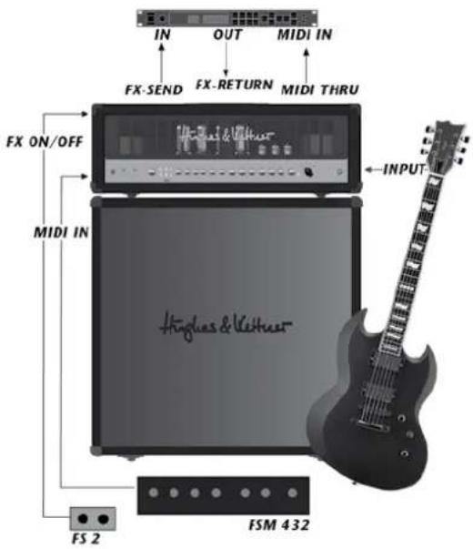
Always remember to never operate your CORE BLADE without a connected speaker cabinet. Also ensure the cabinet's impedance value measured in colours matches that of the selected. Never use outputs for different impedances at the same time! See section 5.1.
D E 's
Input
Plug your guitar in here. Please use quality cords designed for guitars only.
Connect the included FSM 432 MIDI board to this port so you can select presets. You need the FSM 432 or another MIDI board to operate all of COREBLADE's functions. See section 1.2.3 for more about this. You find more info on the FSM 432 in sections 5.5.1 and 7.1.
Do This before Hitting the On Switch
A word of warning before you fire up your CORE BLADE : It's loud! I volume levels can cause hearing damage. Spare yourself nasty surprises and make a habit of twisting the MASTER knob to the far left before turning on the amp.
Mains
This switch enables mains current to flow. When you engage it, the blue pilot lamp illuminates and the tubes begin heating up. Ensure the STANDBY switch is set to the down position, and give the tubes at least 30 seconds to get toasty. They'll thank you for your patience by lasting longer.
Standby
The STANDBY switch gets the tube's anode current flowing and brings the amp online. Please use the STANDBY rather than the MAINS switch when taking short breaks so tubes remain at their operating temperature.
Factory Presets
COREBLADE ships with 18 banks, each offering four sample presets
accessible via the FSM 432. These presets will help you discover the many sound
design options C O R E B L A D E has to offer. Feel free to edit
these factory sounds as you see fit. But more on this later; now it's time for some
fun! If you can't wait to get to it, go ahead and play your COREB
But before you take it to the stage, please read these instructions carefully and completely. Chapters 1 and 5 are mandatory reading even for seasoned players.
Standard Setup and Cable Connections
text_image
IN OUT MIDI IN FX-SEND FX-RETURN MIDI THRU FX ON/OFF MIDI IN INPUT Hingles & Veithue FS 2 FSM 432Table of Contents
ole presets
1 The Fundamentals of Handling COREBLADE
1.1 How the Knobs Work and overwrite
1.2 Selecting Presets Using the Included FSM 432 MIDI Board
A D E.
2
2.1 CLEAN Channel
2.2 DRIVE Channel
2.3 ULTRA I Channel
2.4 ULTRA II Channel
2.5 GAIN
2.6 BOOST
2.7 BASS, MID, TREBLE
2.8 RESONANCE
2.9 PRESENCE
2.10 VOLUME
3
3.1 REVERB
3.2 DELAY
3.3 MOD FX
4
4.1 MASTER
4.2 MEMORY STICK/AMP
4.3 STORE
4.4 COPY MEMORY
4.5 NOISE GATE
4.6 FX-LOOP
5
5.1 LOUDSPEAKER OUTPUTS
5.2 AMP TO STICK / STICK TO AMP
5.3 EFFECTS ON/OFF
5.4 STAGEBOARD CHANNEL SELECT
5.5 MIDI
5.6 FX LOOP
5.7 NOISE GATE SENSIVITY
5.8 TUBE SAFETY CONTROL (TSC ^™ )
5.9 HUM BALANCE
6
6.1 The basics briefly explained
6.2 'The benefits of TSC ^TM
6.3 What the Tube Status Control tells you
6.4 Matching Tubes with TSC™
7
7.1 Setting up the FSM 432
7.2 Setting the MIDI Channel and Switching OMNI On/Off
7.3 Factory Settings and How to Restore Them (Factory Reset)
8
8
Replacing Tubes, Service and Preventive Maintenance
9
9 Troubleshooting
1
10 Technical Specifications
1 The Fundamentals of Handling COREBLADE
2 The Channel Section
COREBLADE is a tube amp, and it works much like other tube amps. REBLADE sports four channels, each voiced very differently and
But its handling concept is more advanced, so time spent getting to know how it operates is time well spent.
1.1 How the Knobs Work
One set of knobs controls all four channels. Your choice of channel determines the knob's assignment, for example, which of the CLEAN, DRIVE, or ULTRA channels the GAIN knob addresses at the given moment. The great advantage of this design is that the channels are truly independent and do not share GAIN, VOLUME, or tone controls. You can even adjust PRESENCE and REVERB settings separately for every channel!
NOTE: The knobs look and feel like standard-issue pots with a 300-degree control range and left and right stops. But there's a difference that may take some getting used to: The knob setting programmed in a preset is independent of the knob's physical position. In other words, when you switch from one preset another, the knob's actual position may not reflect the setting programmed in the preset, and you may well hear something other than what you're seeing would suggest. The knob will respond like any other conventional pot as soon as you move it. The S'ORE LED in the MASTER section tells you the knob setting stored in the preset. It lights up when the physical position of the knob corresponds to the preset setting. More on this in section 4.3.
HEADS UP: You may hear soft background noise when twisting knobs. This sound is made the Programmable Resistor Matrix, or PRN ^™ for short, as it switches.
1.2 Selecting Presets Using the Included FSM 432 MIDI Board
The FSM 432 serves to select the 128 memory slots arranged in 32 banks of four presets each. You can easily configure setups any way you wish, say by assigning the four presets of a bank to a song.
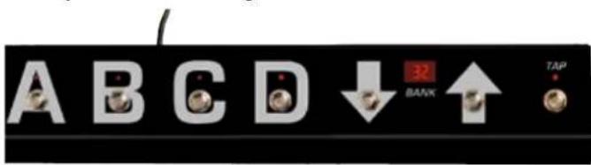
text_image
A B C D ↓ 32 BANK ↑ TAP1.2.1 PRESET A B C D
Presets within a bank activate directly, that is, you can switch straight from A to B within the same bank. The LED above the A, B, C, and D buttons indicates the select preset.
1.2.2 BANK UP/DOWN
To access a preset in another bank, select the target bank using the UP and DOWN buttons. You can continue playing with the current preset while you're navigating. The display shows the bank's number; it flashes until you select a preset by pressing A, B, C, or D. The FSM 32 switch will not switch over to the new preset until you do this.
1.2.3 TAP
TAP offers you a quick, convenient way of adjusting delay time. It's particularly handy on stage: Simply tap your foot on the TAP button in time with the beat to match delay time to the tempo. See section 3.2 for more info.
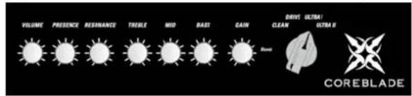
accessible via a chicken-head selector switch. 'The power amp feedback circuit, which has a formative hand in shaping your tone, is also reconfigured during channel switching. The programmable knobs afford you full access to all sound parameters in every channel. We even painstakingly fine-tuned knobs' control ranges and characteristics to match the selected channel's voicing.
text_image
VOLUME PRESENCE RESHANCE TREBLE MID BAST CAIN DAYS ULTRA! CLEAN USTRAL COREBLADE2.1 CLEAN Channel
COREBLADE's CLEAN channel certainly merits its name. It delivers sparkling fresh sounds, offers oodles of headroom, and remains undistorted even when driven by high-output pick-ups. It's worth your while to experiment with different GAIN settings in combination with the switchable BOOST.
2.2 DRIVE Channel
Your first stop for classic overdrive at its finest. This channel sweeps the sonic spectrum from clean to mean, and countless tones in between. Engage BOOST to conjure a rude rock roar.
2.3 ULTRA I Channel
Look no further for modern high-gain sound with all the articulate response of a Teutonic tone-generator. This channel's masterfully musical compression sends those riffs and licks flying off your fingertips. Hit BOOST for an extra helping of in-your-face sound pressure.
2.4 ULTRA II Channel
Get your high-gain tone right here. The ULTRA II channel's top end slices, dices, but never sacrifices its thunderous low end for raging metal riffs and larger-than-life lead tune. Dropped tuning conjures a quasi religious experience.
2.5 GAIN
The GAIN knob determines input sensitivity and therefore the preamp's saturation level. Paired with BOOST, it is your most important sound-sculpting tool.
2.6 BOOST
BOOST targets specific frequency ranges and kicks them up a notch. This yields even more assertive, creamier, or punchier tone, depending on the channel.
2.7 BASS, MID, TREBLE
The three-band voicing section's sound-shaping action is fine-tuned for each channel, and specifically addresses the frequency ranges that define each channel's characteristic tone.
HEADS UP: These are classic passive tone controls that influence one another. For example, if you crank the MID knob, the BASS knob will be less effective than when you back the MID knob down. PRESENCE and RESONANCE are independent of the three-band voicing controls; that is, their action remains unaffected by other knobs' settings.
2.8 RESONANCE
Set the RESONANCE knob to 12 o'clock and you will hear the normal resonance created by the amp-and-cabinet combination. Twisting it to the counterclockwise dampens the speakers and the cabinet's resonance for a looser,
softer sound that sweetens up clean tone. Turning the knob clockwise intensifies resonance for a tighter, punchier low-end that works well with distorted sounds.
2.9 PRESENCE
This knob control the amount of harmonic overtones generated by the amp - the higher the setting, the more intense the effect.
2.10 VOLUME
Use the VOLUME knob to adjust presets' levels and adjust their relative balance.
HEADS UP: Unlike a conventional VOLUME control, this knob does not bring the level all the way down; it merely boosts or cuts the given level. The 12 o'clock position is the best starting point for adjusting volume.
CAUTION: Please don't use this knob to control the amps' overall output level – that's the MASTER knob's job.
3 The Effects Section
COREBLADE offers three independent effect modules that you can use
simultaneously.
HEADS UP: The far left knob position bypasses the effect. Twisting the REVERB VOLUME, DELAY VOLUME, and INTENSITY knobs counterclockwise to the far left takes the given effect module out of the signal path.
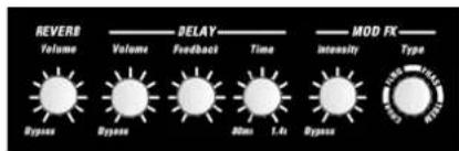
text_image
REVERB Volume Dypass Volume Delay Feedback Time MOD FX Intensity Type DIP DIP 0.0ms 1.4s Dypass3.1 REVERB
COREBLADE's reverb is modeled to match the warmth an
of classic spring reverbs. A genuine improvement over its analog forebears, it automatically adjusts the reverb tail - the higher the REVERB VOLUME setting, the longer the reverb time.
3.2 DELAY
The DELAY module's VOLUME, TIME, and FEEDBACK knobs afford you total control over all parameters.
3.2.1 VOLUME
Adjusts the volume of repetitions, sweeping from all the way off to just as loud as the original signal.
3.2.2 FEEDBACK
Adjusts the number of repetitions from one to infinite.
3.2.3 TIME
Adjusts the time to the next repetition from 80 milliseconds to 1.4 seconds.
When you're tapping in delay time on the FSM 432, the effect adopts the new time after your second tap. The TAP LED flashes for about five seconds in sync with the beat to give you a visual indication of delay time. The TAP function works only when the DELAY is active. If the DELAY is off – or more accurately, bypassed - the effect will not adopt your TAP tempo.
HEADS UP: You can also set delay time using MIDI control controller change number 4 and an MSB value between 0 (80 ms) and 127 (1360 ms). The values for the 128 steps of 10 milliseconds each are easily determined by subtracting 80 ms from the target time and dividing the result by 10. Say you're aiming for 500 ms. (500-80)/10 = 42, so the MSB value is 42. You can even adjust the time in 5-ms intervals by sending the MSB value along with an LSB value of 1 using controller change number 36, which always adds 5 ms to the total. The combination of MSB 42 and LSB 1, for example, gives you 505 ms.
3.3 MOD FX
This module serves up a smorgasbord of four modulation effects - CHORUS, FLANGER, PHASER, and TREMOLO.
3.3.1 TYPE
Each effect is assigned to one quarter of this knob's control range. The first quarter addresses CHORUS, the second addresses FLANGER, the third addresses PHASER, and the final quarter addresses TREMOLO. You can adjust the modulation effect's rate within its assigned quarter, and even beyond that. 'The bars – or more accurately, arches – between CHRS, FLNG, PHAS, and TREM on the knob's label indicate each effect's extended control range. When you select an effect, its assigned quarter of the control range is extended to include the neighboring arch. This gives you greater leeway to shape sounds as you see fit.
3.3.2 INTENSITY
This knob adjusts the volume of the modulation effects.
4 The Master Section
The MASTER section lets you adjust the amp's overall volume, switch the IDB™
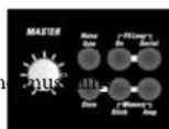
Noise Gate, route external effects, store presets, and determine if the amp sources presets from its memory or from the memory stick.
4.1 MASTER
As the name suggests, this knob puts the power amp and its volume level at your thumb and forefinger's command. Handle it carefully and you will enjoy a gratifying rather than an agonizing aural experience.
HEADS UP: Unlike channel and effect controls, the MASTER knob is not programmable! It works like any conventional knob, and its physical position indicates the actual setting. It's always a good idea to back the MASTER knob off, twisting it to the far left position before powering the amp up.
4.2 MEMORY STICK/AMP
The STICK and AMP buttons on COREBLADE's front panel do the source and target memory for presets – that is, if they are accessed from and stored to the amp's internal memory or a memory stick. COREBLAD rear panel provides the means to download a backup of the internal memory to the memory stick and upload a complete setup from a memory stick to the internal memory. See section 4.4 for more on this.
HEADS UP: The AMP button is disabled and its light remains off when the USB port is unoccupied. The AMP button is enabled and lights up when you plug in a memory stick containing presets.
4.2.1 Plugging in a USB Stick:
Below the STICK button you'll find a USB port that accepts a memory stick. You can plug it in before powering the amp up or while it's up and running. The light on the STICK button flashes three times to tell you the memory stick is good to
go and usable data has been detected on the memory stick. If this light does not flash, the memory stick is empty, faulty, or unformatted. You can remove it at any time, apart from the few seconds it takes to store or copy presets, in which case data may be lost when you unplug the stick. If the STICK button is enabled and the memory stick is removed while you're playing, the STICK light will extinguish. However, you can continue playing with that preset until you switch over to another preset.
4.2.2 Which Memory Sticks Work
Almost all USB sticks formatted in standard FAT-16 or FAT-32 formats will work, apart from U3-type sticks (see the paragraph below for more on this). Please use your chosen memory stick only to store CORE BLADE p other files such as mp3s, pictures, or videos can lead to data loss. Do not use a mobile phone, digital camera, MP3 player or any storage medium other than a memory stick. We can't guarantee that another storage media will work and keep your data safe.
HEADS UP: The USB port is sited very close to the bottom edge of the housing. Very thick USB sticks may not fit, but this location's benefit outweighs that drawback: Standard flat memory sticks sit securely and snuggly right on the panel so they won't break off.
U3 sticks: Some USB sticks are designed to run computer programs without prior installation. They can cause conflicts, which is why we recommend that you do not use U3 sticks.
4.2.3 Accessing Presets on a USB Stick
The AMP button lights up to tell you that CORE BLADE memory stick. Rather than automatically switching over to the memory stick, the amp will continue using its internal presets. To access the sounds on the memory stick, all you have to do is press the STICK button. It will light up and wait for you to select a preset using the FSM 432 (A, B, C, or D) or a MIDI program change command. Again, the amp will not call up the preset on the memory stick until you tell it to do this. In the meantime, you can continue playing without interruption using the preset most recently selected from CORE BL internal memory.
4.3 STORE
Use the STORE button to save your presets and read out the knob settings stored in the given preset.
4.3.1 Reading out Stored Knob Settings
When you select a preset, the knob's actual position may not represent its stored value. But it's easy enough to read out: Select a preset, grab the knob and twist it to the left or right until the STORE button lights up. The setting at which the LED lights up is the setting stored in the preset. Now the knob's position matches the value stored in the preset.
4.3.2 Storing Settings by Overwriting the Currently Selected Preset
An easy way to store edited settings is to simply overwrite the most recently selected preset. To do this, press and hold the STORE button for about two seconds until its light flashes briefly and then extinguishes. The CHANNEL LED also flashes to confirm the write operation. Release the STORE button, and your settings will be stored.
4.3.3 Storing Settings by Selecting a New Memory Slot
If you do not wish to overwrite the current preset, you can easily select a new memory slot instead. In this case, rather than holding the STORE button down for two seconds, press it briefly and then release it. Its light stays on to signify
that COREBLADE is primed and ready to receive a memory FSM 432 or via MIDI:
- Select a MIDI bank from 1 to 32 on the FSM 432. It flashes to signify that the
FSM 432 is waiting for input via one of the four preset buttons A to D.
- Engage preset button A, B, C, or D. The board stops flashing, the light on the STORE button extinguishes, and the preset is stored.
CAUTION: A BANK UP/DOWN command also triggers a store operation when the FSM 432 is in DIRECT MODE (see section 7.1.2). We suggest you deactivate DIRECT MODE when you're programming to ensure you don't accidentally overwrite presets.
When you're using a memory stick and the amp is primed, you can select AMP or STICK to determine if the preset will be stored in the amp's internal memory or
presets.thoring memory stick. However, this will only work if CORE BLADE detected the memory stick; that is, if the memory stick contains a backup file into which CORE BLADE can dump the preset. This lets you copy individ presets from the amp to the memory stick and vice versa, say to put together your best-of setup. Once the storage process is concluded, CORE BLADE returns to the initial memory slot.
Here's how to proceed for other manufacturers' MIDI boards and MIDI-enabled devices: Prime CORE BLADE by engaging the STORE button, and then send a program change command from the MIDI-enabled device. As soon as
COREBLADE receives a valid program change command, the STOR button extinguishes to indicate the preset has been stored and assigned to the given MIDI-enabled device.
If an error occurs (the amp remains primed), you can cancel the store operation by briefly pressing STORE again.
has detected the
HEADS UP: Storing presets to a USB stick takes longer than storing them in the internal memory. The light on the STICK button flashes intermittently during the few seconds it takes to store presets. Please do not engage any of COREBLADE's control features during this time, and definitely do not remove the memory stick!
A1.4 DOPE MEMORY
COPY MEMORY lets you download and upload presets so you can take them with you. Be aware that:
- There is only one file called memory.dat for all presets. Rather than storing 128 sounds individually, CORE BLADE generates a complete backup coi its internal memory.
- Only one backup file is permitted per memory stick. COREBLADE ignores all files but one – the file named memory.dat!
- If you want to create different preset setups, you'll need a dedicated memory stick for each.
This method is the safest and simplest way of managing setups. And you don't need any other software to copy the memory.dat file from the memory stick to a computer, store it there, and disseminate it, say via e-mail.
4.4.1 Dumping a Backup to a USB Stick
The AMP TO STICK button on CORE BLADE's rear panel dumps a internal presets to the memory stick in one go. To create a backup, press and hold the AMP TO STICK button for about three seconds until it lights up. You can release the button when its light flashes intermittently during the dump. It will flash again after a few seconds to confirm what has happened:
- The AMP TO STICK button flashes twice slowly to indicate everything's OK.
- It flashes four times quickly to alert you to an error. The memory stick may be full, unformatted, or locked.
My slot from the if you are using a memory stick with a hardware lock, please ensure it is unlocked. COREBLADE may not be able to detect the hardware lock's status and data could be lost!
4.4.2 Uploading All Presets from a Memory Stick to the Internal Memory
The STICK TO AMP button on CORE BLADE's rear panel uploads:all
presets on the memory stick to CORE BLADE's internal memory in one
go. To initiate an upload, press and hold the STICK TO AMP button for about three seconds until it lights up. You can release the button when its light flashes intermittently during the dump. It will flash again after a few seconds to tell you what has happened:
- The AMP TO STICK button flashes twice slowly to confirm everything's OK.
- It flashes four times quickly to alert you to an error. Presets were not copied and internal presets were not overwritten.
If the button fails to light up even after you press it for several seconds, the amp is unable to detect presets on the memory stick.
CAUTION: Copying presets from the memory stick is an irreversible process that overwrites all internal presets. We recommend that you first back up all your amp's presets to another memory stick.
4.5 NOISE GATE
The programmable NOISE GATE button switches the IDB™ noise gate on and off for each preset. When activated, the noise gate kicks in to mute the amp as the signal level drops below a certain threshold. The gate remains shut until you hit the guitar strings, when it opens up again.
4.5.1 SENSITIVITY
The SENSITIVITY knob on the amp's rear panel controls the noise gate's response. The knob's far left position is labeled HARD; its far right position is labeled SOFT. The noise gate's IDB™ technology automatically adapts the standard attack and threshold parameters. Outboard noise gates sandwiched between the guitar and amp or plugged into the FX loop can only measure the signal at one point. This technology gauges the signal at two points, directly at the INPUT jack and post preamp, but pre effects. The noise gate uses these two values to calculate the optimum response. What's more, it does not cut off REVERB and DELAY signals.
The further you twist the SENSITIVITY knob to the right, the more sensitive the noise gate's response. Set it to 12 o'clock if you want it to open up at very soft signal levels. The further you twist the knob to the left, the harder the noise gate kicks in and cuts off signals.
HEADS UP: The SENSITIVITY knob's setting applies to all presets that incorporate the noise gate. This is convenient and intentional: If conditions on stage are different in the rehearsal room, you can adjust the noise gate's response for all presets with one simple tweak.
TIP: 12.0'clock is the universal setting. It you wish to use the noise gate as a stylistic device when playing fast staccato riffs at high gain levels, then dial in a setting towards the HARD end of the control range.
4.6 FX LOOP
The programmable SmartLoop ^™ effects routing circuit offers parallel/ serial effects loop for patching in external effect devices.
Its status - on or off and parallel or serial - is stored with each preset.
4.6.1 SERIAL
Switches the effects loop from parallel (LED does not light up) to serial (LED lights up).
4.6.2 FX ON
Switches the effects loop on (LED lights up) and off (LED does not light up).
TIP: If you have not inserted a signal processor into the FX loop, you can use it for purposes other than effects, and even store the configurations individually in
elauploadcall
- In parallel mode, you can use the RETURN jack to connect a second instrument or any other audio source, and even route the amp's signal to a second power amp.
- In serial mode, the effects loop lets you control the amp's volume remotely by connecting an analog volume pedal to the SEND/RETURN jacks.
- The serial effects loop also lets you patch in an outboard equalizer to serve as a master EQ, say to adapt the amp to another cabinet or a venue's acoustics.
CAUTION: The signal chain is severed if you configure the FX loop serially but do not connect an effect device. SEND is not the best to-mixer routing option because it taps the preamp signal only. You're better off patching the power amp signal to a mixing console from the speaker outputs via a Hughes & Kettner Red Box".
HEADS UP: FX ON/OFF is footswitchable. Connecting a footswitch disables the front panel button. See section 5.3 for more info.
5 Rear Panel Connections and Control Features
text_image
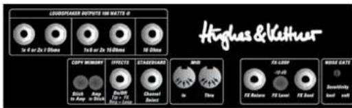
LONGPLASTER OUTPUTS 100 WATTS 0 Hughes & Veather CoPI MEMORY EFFECTS STANDARD MRR EX LUXO NOG GATE Black Red Blue White Grey Black White 1x 6 or 2x 100ms 1x 8 or 2x 100ms 100ms 100ms 300ms 300ms 300ms 300ms 300ms 300ms 300ms 300ms 300ms 300ms 300ms 300ms 300ms 300ms 300ms 300ms 300ms 300ms 300ms 300ms 5x 4x 3x 2x 1x 0x 1x 2x 3x 4x 5x 6x 7x 8x 9x 10x 11x 12x 13x 14x 15x 16x 17x 18x 19x 20x 21x 22x 23x 24x 25x 26x 27x 28x 29x 30x 31x 32x 33x 34x 35x 36x 37x 38x 39x 40x 41x 42x 43x 44x 45x 46x 47x 48x 49x 50x 51x 52x 53x 54x 55x 56x 57x 58x 59x 60x 61x 62x 63x 64x 65x 66x 67x 68x 69x 70x 71x 72x 73x 74x 75x 76x 77x 78x 79x 80x OFFICE ON CHAMPION INCHANCE INCHANCE INCHANCE INCHANCE INCHANCE INCHANCE INCHANCE INCHANCE INCHANCE INCHANCE INCHANCE INCHANCE INCHANCE INCHANCE INCHANCE INCHANCE INCHANCE INCHANCE INCHANCE INCHANCE INCHANCE INCHANCE INCHANCE INCHANCE INCHANCE INCHENCE INCHANCE INCHANCE INCHANCE INCHANCE INCHANCE INCHANCE INCHANCE INCHANCE INCHANCE INCHANCE INCHANCE INCHANCE INCHANCE INCHANCE INCHANCE INCHANCE INCHANCE INCHANCE INCHANCE INCHANCE INCHANCE INCHANCE INCHANCE INCHANCE INCHANCEL5.1 LOUDSPEAKER OUTPUTS
COREBLADE offers separate outputs for all standard impedance can connect either one 4 Ω cabinet, or two 8 Ω cabinets, or two 16 Ω cabinets, or one 16 Ω cabinet. Never connect different cabinets at the same time! If you want to drive two cabinets with different impedances simultaneously, you must configure a parallel circuit and connect it to the appropriate output. Use this formula to figure out the overall impedance (R) of two cabinets with different impedances (R1, R2) connected in parallel:
$$ \mathrm{R} = (\mathrm{R1} \times \mathrm{R2}) / (\mathrm{R1} + \mathrm{R2}) $$
Here's an example with one 8Ω cab and one 16Ω cab
$$ R = (8 \times 1 6) / (8 + 1 6) $$
$$ \mathrm{R} = 1 2 8 / 2 4 $$
$$ R = 5. 3 3 $$
The golden rule is cabinets' impedance may never be lower than the amp's output impedance. So, you would connect this combination of cabs to the 1 x 4 Ω speaker out.
5.2 AMP TO STICK / STICK TO AMP
These buttons let you download and store the amp's internal presets on a USB stick and upload them any time, even to a another CORE BLADE read section 4.4 for more about this.
5.3 EFFECTS ON/OFF
This port accepts a two-way footswitch such as the Hughes & Kettner® FS-2. Button 1 switches internal effects; button 2 the external effects loop. The FS-2's LED lights up to indicate effects are active and the FX ON button is engaged.
It does not light up if the internal effects are bypassed; that is, the FX ON button is not engaged.
HEADS UP: The footswitch disables the front panel FX ON button. A connected footswitch always has priority. 'The footswitch's current status is valid when you switch channels. The front panel FX ON button then serves as an LED display indicating the footswitch's status.
5.4 STAGEBOARD CHANNEL SELECT
This fall-back footswitch connector will help get you through the gig if you left your MIDI board behind. It lets you switch remotely between two channels, say CLEAN and ULTRA II, using a standard one-way footswitch such as the Hughes & Kettner® FS-1. A two-way footswitch such as the Hughes & Kettner® FS-2 may also be connected. In this case, button 1 switches channels, and button 2 does nothing. COREBLADE even accepts the four-way Hughes FS-4 footswitch that ships with Hughes & Kettner® Trilogy and Matrix amp. It lets you switch all four channels.
HEADS UP: The footswitch changes the channels only, and not presets.
5.5 MIDI
COREBLADE comes with a standard MIDI interface that with other MIDI devices and accepts the included FSM 432.
5.5.1 MIDI IN
Though this is a 7-pin interface, you can connect a standard 5-pin MIDI cable. The two additional terminals serve to supply phantom power to the FSM 432.
HEADS UP: The FSM 432 comes with a 7-pin MIDI cable. You do not need a power source for the FSM 432 because phantom power is provided. If you wish to use a 5-pin MIDI cable, you will however need a wall-wart. It provides an innovative mains port that accepts any AC or DC adapter rated for 9 to 15 volts.
5.5.2 MIDI THRU
This port forwards signals patched into MIDI IN to other devices. You can connect any external MIDI-enabled signal processor that you wish to switch synchronously with COREBLADE.
5.6 FX LOOP
If you wish to use an outboard effect device, you can insert it into the FX LOOP.
5.6.1 FX SEND
Connect this jack to your effects processor's input.
5.6.2 FX LEVEL
This button the FX SEND's output level by 10 dB and boosts FX RETURN's input sensitivity by 10 dB to match the FX loop to the effect device's input level. Press this button when using processors designed to handle instrument levels.
5.6.3 FX RETURN
Connect this jack to your effects processor's output.
5.7 SENSIVITY
The SENSIVITY knob controls the noise gate's response. The programmable NOISE GATE button on the front of the amp activates and deactivates the noise gate for each preset. See section 4.5 to learn more about this.
5.8 TUBE SAFETY CONTROL (TSC™)
Chapter 6 is devoted to the Tube Safety Control - read it to get all the details.
5.9 HUM BALANCE
This trim knob adjusts the balance to minimize hum after swapping preamp tubes. See chapter 8.
6 TUBE SAFETY CONTROL (TSC ^™ )
TSC™ adjusts bias to improve CORE BLADE's tonal and technical sta and extend power tubes' life. It does this automatically, so there is nothing for you to do.
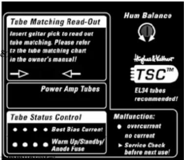
text_image
Tube Matching Read-Out Insert guitar pick to read out tube matching. Please refer to the tube matching chart in the owner's manual! Power Amp Tubes Hum Balance TSC™ EL34 tubes recommended! Tube Status Control ●●●● Best Bias Current ●●●● Warm Up/Standby/ Anode Fuse Malfunction: ● overcurrent no current ► Service Check before next use!It also offers some more hip features for dealing with different makes and types of power output tubes (EL34 and/or 6L6GC) that are likely to interest you. If not, simply handle the amp as you would any conventional tube amp. But please read and heed chapter 8, Replacing Tubes, Service and Preventive Maintenance,
and section, 6.4 Matching Tubes with TSC ^™ , to get all the facts straight about replacing and matching tubes. This knowledge will spare you a lot of hassle and effort.
6.1. The Basics Briefly Explained
NOTE: We developed 'TSC™' exclusively for power output tubes, and this chapter addresses only this type of tube.
What's up with bias, ratings, and matching?
In a tube amp, bias describes the amount of idle current flowing in the tube grid. A technician should adjust or re-bias this idle current regularly, and certainly after replacing output tubes with others bearing different ratings. Biasing is necessary because tubes and their component parts are delicate, their tolerances vary somewhat, and they have different bias points and thus different ratings. Vibrations, temperature variations, and plain old aging can even affect a tube's bias point over its lifetime. If several tubes share the same bias point or rating, we say they are matched. And we always use matched tubes in a guitar amp to ensure they bear the load equally, which reduces wear, extends tube life, and yields better tone. Courtesy of TSC ^™ , all tubes in CORE BLADE share the same lo even if they have different ratings.
TSC ^™ is a very different breed of auto-biasing solution. For one, it really is automatic, meaning that you don't have to activate it manually. For another, it readjusts bias only when it makes sense to do so – when the amp is in fact idling every time it is powered up and you take a break from playing! And TSC ^™ takes a break while you play to ensure it doesn't adversely affect your tone!
6.2 'The Benefits of TSC'
1) You can swap tubes easily, quickly, and safely:
All the hard work of biasing gets done automatically, so swapping tubes is an exercise in speed and convenience. This is a big help not only in case of a defect, but also when you want to compare different brands, different ratings, and even different types of replacement tubes. CORE BLADE accepts all type E and 6L6GC tubes, even in mixed combinations! Consider this before replacing tubes: We designed the amp's factory presets specifically for EL 34 tubes. Also, if another type of tube is installed, you will have to modify your presets to achieve the best audio results.
CAUTION: Replacing tubes is a job best left to qualified professionals! TSC ^™ spares the technician the biasing effort, but the service guidelines in chapter 8 remain valid and must be followed.
2) You can continue playing despite a defect: TSC ^™ shuts a faulty tube down and an LED indicates the defect. You can continue playing and the amp will get you through the gig.
3) You can easily check tube ratings: You can check a tube's bias point and determine if pairs match any time you wish without taking the amp to a tech. All you need to do this is a pick. See section 6.4.1 for more on this.
4) Tubes last longer: TSC ^™ always adjusts bias to the optimum operating point, thereby preventing excessive current from overloading tubes.
5) You enjoy optimum sound: TSC ^™ minimizes undesirable crossover distortion even when tubes' bias points diverge strongly.
6.3 What the Tube Status Control tells you
Each of the LEDs in side-by-side array is assigned to the power amp tube occupying that same position. TSC ^™ automatically indicates tubes' operating status as soon as you switch STANDBY off to turn the amp on. You can activate the display's readout manually by inserting a pick into the slot to view tubes' bias points and match sets on your own.
6.3.1 All LEDs Off
Power output tubes are operating normally.
6.3.2 All LEDs Light Up and Stay On
All LEDs remain on for as long as the amp is in standby mode to indicate tubes are heating up but no current is flowing to them. Leave the amp on standby for about 30 seconds, and the LEDs will extinguish when you switch from standby to on. If the LEDs continue to light up, the most likely cause is a blown anode fuse that needs to be replaced. It is on the rear panel, readily accessible from outside the amp. The fuse can trip if a tube is already defective when the amp is switched on, and TSC does not have enough time to measure idle current and shut the faulty tube down. This may occur in case of serious tube defects such as a short-circuit caused by the anode and cathode making direct contact, or voltage spikes occurring when using older tubes and fuses. If you experience one of these rare events, have a technician replace the tubes and fuses. See chapter 8 to learn more about this.
6.3.3 One LED Lights Up Continuously
The tube assigned to this LED is producing under-voltage. If the LED fails to extinguish after a few minutes, the power output tube must be replaced. Please read and heed the instructions in chapter 8.
6.3.4 One LED Flashes, Another Lights Up Continuously
The tube assigned to this flashing LED is generating over-voltage. It has been shut down and must be replaced as described in chapter 8. In this type of power amp, it takes a pair of tubes working together to produce the best sound. The defective tube's counterpart is switched off so it doesn't degrade the other pair's tone. This tube's LED lights up continuously to indicate it has also been shut down, but there is no need to replace it. You can continue playing, though output is halved from 100 to 50 watts for as long as the LED remains illuminated. If this occurs in a conventional amp, its fuse usually trips and you can't operate it until you replace the tube and fuse.
6.4 Matching Tubes with TSC ^™
TSC ^™ lets you check installed tubes, as well as replacement tubes before and during installation.
6.4.1 Getting a Read-Out
Insert a pick into the slot in the panel labeled Tube Matching Read-Out while the amp is on (rather than in standby mode). All LEDs will flash. How many times the LEDs flash matters, but what matters more is the difference in flash counts. If the rating deviates upward or downward by six or more flashes, the bias points are too far apart for TSC ^™ to compensate. The given power output tube must be replaced to achieve optimum sound.
The tables in section 5.3.3 show Hughes & Kettner tube ratings. You can buy tubes with the same ratings from your local dealer. You'll find a sticker with the original Hughes & Kettner rating (S1-S3, 0-9) on the power output tube. Bear in mind that if you're using different types of tubes - that is, EL34s and 6L6GCs - you must consider the flash signals separately for each tube type. The table in section 5.3.3 shows you how the flash count translates to a rating.
6.4.2 Checking for matching ratings after swapping tubes
If all tubes are replaced, ensure they all have the same ratings. The choice of rating is up to you, and TSC ^™ spares you biasing effort. If just a single tube is swapped, ensure the replacement tube's rating matches the ratings of the other tubes in the amp.
6.4.3 Tube ratings tables
| EL34 power output tubes | 6L6 power output tubes | ||
| flashes rating flashes rating | |||
| 1 S3 1 -- | |||
| 2 S2 2 -- | |||
| 3 S1 3 -- | |||
| 4 0 4 -- | |||
| 5 1 5 S4 | |||
| 6 2 6 S3 | |||
| 7 3 7 S2 | |||
| 8 4 8 S1 | |||
| 9 5 9 0 | |||
| 10 6 10 1 | |||
| 11 7 11 2 | |||
| 12 8 12 3 | |||
| 13 9 13 4 | |||
| 14 10 | 14 5 | ||
| 15 11 | 15 6 | ||
| 16 12 | 16 7 | ||
| 17 13 | 17 8 | ||
| 18 14 | 18 9 | ||
| 19 | -- | 19 10 | |
| 20 | -- | 20 11 | |
| 21 | -- | 21 12 | |
| 22 | -- | 22 12 | |
| 23 | -- | 23 13 | |
| 24 | -- | 24 13 | |
| 25 | -- | 25 | 14 |
| 26 | -- | 26 14 | |
| 27 | -- | 27 14 | |
7 MIDI Control and Programming
The MIDI interface serves mainly to control COREBLADE using the included FSM 432. But you can also control the amp using other MIDI devices, as well as remote-control other MIDI receivers using the FSM 432.
7.1 Setting Up the FSM 432
7.1.1 Direct Mode
DIRECT MODE lets you trigger a direct program change via BANK UP/DOWN. In this mode, the FSM 432 will not wait for your input by way of the A, B, C, or D buttons, instead switching directly, for example, from preset B
in bank 16 to preset B in bank 17 (UP) or bank 15 (DOWN). Here's how to activate DIRECT MODE:
- Press and hold TAP, and then press PRESET A.
- First release PRESET A, and then TAP. 'The decimal point in the display lights up.
Follow the same sequence to deactivate DIRECT MODE. Note that it is a volatile rather than a permanent mode. CORE BLADE reverts to standard mode when you switch the amp off.
7.2.2 Setting the FSM 432's MIDI Send Channel
If you wish to switch devices connected to COREBLADE say, a MIDI multi-effector – using the FSM 432, ensure it is set to the FSM 432's MIDI channel or to OMNI. Consult the device's manual for more info.
To set the FSM 432's MIDI send channel, proceed as follows:
- Turn COREBLADE on while pressing the FSM 432's PRESET A button. The display flashes.
- Release button A. Use UP/DOWN to view and set the MIDI channel to a number between 1 and 16.
- Quit and store by pressing the PRESET A button.
CAUTION: If COREBLADE and the FSM 432 are not set to the same MIDI channel, the amp will not respond to program changes! Activating OMNI solves the problem if all else fails. See section 7.3 for more on this. The factory default is channel 1.
HEADS UP: If an external effect device is connected to MIDI THRU and you want to switch COREBLADE and the effect device simultaneously with the same program change command, you must configure COREBLADE's STORE function and program this device accordingly.
NOTE: The table below should be big help if you wish to switch the presets of a device connected to the MIDI THRU directly via the FSM 432. It shows the program changes sent by the bank/preset combination. Please bear in mind that some MIDI devices switch program 1 via program change command 0. If this is the case with your outboard gear, simply add a 1 to each value indicated in this table to activate the desired program.
| Bank | Preset | Programchange Number | Bank | Preset | Programchange Number | Bank | Preset | Programchange Number | Bank | Preset | Programchange Number |
| 1 A | 0 9 A | 32 17 | A 64 | 25 A 96 | |||||||
| 1 B | 1 9 B | 33 | 17 B | 65 25 B | 97 | ||||||
| 1 | C | 2 | 9 | C | 34 | 17 | C | 66 | 25 | C | 98 |
| 1 | D | 3 | 9 | D | 35 | 17 | D | 67 | 25 | D | 99 |
| 2 A | 4 10 A | 36 18 | A 68 | 26 A | 100 | ||||||
| 2 B | 5 10 B | 37 | 18 B | 69 26 B | 101 | ||||||
| 2 | C | 6 | 10 | C | 38 | 18 | C | 70 | 26 | C | 102 |
| 2 | D | 7 | 10 | D | 39 | 18 | D | 71 | 26 | D | 103 |
| 3 A | 8 11 A | 40 19 | A 72 | 27 A | 104 | ||||||
| 3 B | 9 11 B | 41 | 19 B | 73 27 B | 105 | ||||||
| 3 | C | 10 | 11 | C | 42 | 19 | C | 74 | 27 | C | 106 |
| 3 | D | 11 | 11 | D | 43 | 19 | D | 75 | 27 | D | 107 |
| 4 A | 12 12 A | 44 20 | A 76 | 28 A | 108 | ||||||
| 4 B | 13 12 B | 45 | 20 B | 77 28 B | 109 | ||||||
| 4 | C | 14 | 12 | C | 46 | 20 | C | 78 | 28 | C | 110 |
| 4 | D | 15 | 12 | D | 47 | 20 | D | 79 | 28 | D | 111 |
| 5 A | 16 13 A | 48 21 | A 80 | 29 A | 112 | ||||||
| 5 B | 17 13 B | 49 | 21 B | 81 29 B | 113 |
| 5 | C | 18 | 13 | C | 50 | 21 | C | 82 | 29 | C | 114 |
| 5 | D | 19 | 13 | D | 51 | 21 | D | 83 | 29 | D | 115 |
| 6 A | 20 14 | A 52 22 | A 84 | 30 A | 116 | ||||||
| 6 B | 21 14 | B 53 | 22 B | 85 30 | B 117 | ||||||
| 6 | C | 22 | 14 | C | 54 | 22 | C | 86 | 30 | C | 118 |
| 6 | D | 23 | 14 | D | 55 | 22 | D | 87 | 30 | D | 119 |
| 7 A | 24 15 | A 56 23 | A 88 | 31 A | 120 | ||||||
| 7 B | 25 15 | B 57 | 23 B | 89 31 | B 121 | ||||||
| 7 | C | 26 | 15 | C | 58 | 23 | C | 90 | 31 | C | 122 |
| 7 | D | 27 | 15 | D | 59 | 23 | D | 91 | 31 | D | 123 |
| 8 A | 28 16 | A 60 24 | A 92 | 32 A | 124 | ||||||
| 8 B | 29 16 | B 61 | 24 B | 93 32 | B 125 | ||||||
| 8 | C | 30 | 16 | C | 62 | 24 | C | 94 | 32 | C | 126 |
| 8 | D | 31 | 16 | D | 63 | 24 | D | 95 | 32 | D | 127 |
7.2 Setting MIDI Channel and Switching OMNI On/Off
Press the SERIAL button longer than two seconds when CORE BLADE is in standard operating mode, and the light on the NOISE GATE LED will start flashing. This assigns special programming functions to the amp's LEDs and buttons:
- FX-ON: Now serves as a +1/UP button for setting the MIDI channel
- SERIAL: Now serves as a -1/DOWN button for setting the MIDI channel
- Switches OMNI mode on and off. If the STORE button (OMNI ON)
lights up, COREBLADE responds to all incoming program changes irrespective of the MIDI channel over which they are sent. If the light on the button is extinguished (OMNI OFF), it responds only to messages sent via the defined MIDI channel.
HEADS UP: OMNI ON is helpful if you are unsure which channel a connected MIDI device is using to send messages.
During the MIDI setup routine, the LEDs that normally indicate the preamp channel indicate the MIDI channel. The following table shows MIDI channel settings:
| MIDI-Channel | Clean | Drive | Ultra I | Ultra II |
| 1 | ||||
| 2 | ||||
| 3 | ||||
| 4 | ||||
| 5 | ||||
| 6 | ||||
| 7 | ||||
| 8 | ||||
| 9 | ||||
| 10 | ||||
| 11 | ||||
| 12 | ||||
| 13 | ||||
| 14 | ||||
| 15 | ||||
| 16 |
Press and hold SERIAL for a few moments to quit the MIDI setup routine and store the settings. The amp returns to its most recent operating status (standard mode).
7.3 Factory Settings and How to Restore Them (Factory Reset)
A factory reset is a seldom needed feature. Even so, be sure to read the explanation carefully to ensure you don't accidentally delete your presets.
7.3.1 Triggering a Factory Reset
Pressing STORE and FX SERIAL simultaneously while powering the amp up resets all settings, including the 128 MIDI-switchable presets and the basic MIDI configuration.
CAUTION: This procedure is a last-resort option! It irrevocably wipes out all stored settings. Before you trigger a factory reset, be sure to first create a backup by copying your amp's internal memory to a stick.
7.3.2 Factory MIDI Defaults
A factory reset also restores the MIDI default settings:
• OMNI ON • MIDI channel: 1
- FX ON switched off
- SERIAL deactivated
8
Replacing Tubes, Service and Preventive Maintenance
The COREBLADE comes factory-equipped with EL34 that were subjected to a battery of tests, painstakingly selected, and matched using Hughes & Kettner's Vacuum Tube Inspector. Ditto for its 12AX7 preamp tubes. This unforgiving test regimen ensures optimum tone and utmost reliability.
8.1 When to Replace Tubes
The tubes in COREBLADE are exemplary in quality, w long life. What's more, the TSC™ module ensures that even veteran power amp tubes run at their optimum bias point, last longer, and sound better.
Telltale signs of wear are increased microphonics, noise and hiss, top-end frequency damping, and poorer performance. These symptoms tell you it's time to replace old tubes because they do take their toll on sound quality and indicate the aging preamp or power tube will soon fail.
8.2 Before you start swapping tubes, ask yourself these questions:
- Was the fault or failure of the tube caused by the tube itself or by a flawed peripheral device or component, perhaps a defective speaker cable? If you don't get to the bottom of the problem and remedy it, it may crop up again even after you replace the tubes.
- Did the mains voltage fluctuate or spike while the amp was on? Spiking voltage in the mains net can cause tube amps to drop out. Generators and faulty high-current power circuits often produce such surges.
- Is the tube really defective or is it just a blown fuse? An old fuse, tube de-ionization, or a flash-over caused by mains voltage power surge may have tripped the fuse
8.3 Replacing Tubes
Replacing tubes is a job best left to qualified professionals! Accordingly, the following guidelines are addressed and apply to qualified service technicians only:
CAUTION: Tubes can remain very hot for quite some time and cause burns even if the amp has been off for several minutes.
Pull the power plug on the back of CORE BLADE and minutes for power to dissipate! Then remove the rear panel. TSC ^™ adjusts bias for you, and the HUM BALANCE trim knob is readily accessible from the outside, so there's no longer any need to remove the chassis. Now you can carefully pull out the tubes while gently pressing down on the clamps that hold them in place.
8.3.1 Replacing Power Output Tubes
You can use EL34s as well as 6L6GCs, and even mixed combinations. There's no need to re-bias the amp - see chapter 6 for on this. However, we strongly advise using matched tubes that share the same ratings.
CAUTION: Use 6L6GC tubes only! 6L6 tubes have different specifications and may not be used in this amp. Check the label on the tube to make sure because 6L6GC are often referred to as 6L6s.
8.3.2 Replacing Preamp Tubes
Be sure to use the same type of replacement tube! You may have to adjust the balance to reduce hum. To do this, proceed as follows:
- Select the CLEAN channel, turn VOLUME, TREBLE, and MID to the left position, and turn BASS to the far right.
- Adjust the HUM BALANCE trim knob on the COREBLADE's rear panel until you find the setting that minimizes humming.
8.4 How to Prolong the Life of COREBLADE's Tube
- Never operate CORE BLADE without connecting a load (louds)
- Never connect speaker cabinets with too high or low impedance!
• Always use high-quality, heavy-duty speaker cords that won't crimp!
weUsehatSTANDBY switch for short breaks!
- Avoid exposing the amp to vibrations, especially when it's powered up.
- Switch the amp off well before transporting it to allow tubes to cool off completely.
- Make sure all peripheral devices and connecting cords are in a state of good repair!
unEnship, airdan circulate freely around the amp's ventilation slots at all times!
- Never expose CORE BLADE to extreme heat or cold!
• Prevent dust and moisture intrusion! - Always check peripheral gear's specs to ensure they are suitable for the amp.
- Never connect devices with high output signal levels to COREBLAD input.
- Never operate the amp with mains power that is too high or too low. When in doubt ask the venue's sound technician or facility engineer.
- Refrain from DIY repairs! Always have a qualified technician replace internal fuses.
9
Troubleshooting
Mains connection: COREBLADE won't power up when you switch it on.
- It's not getting AC power. Check the mains cord to see if it is connected and firmly seated.
- The mains fuse is defective. Ensure it is replaced with another fuse bearing the same rating.
- The local mains voltage does not match CORE BLADE's operating voltage.
Available Voltages and How to Adapt Them
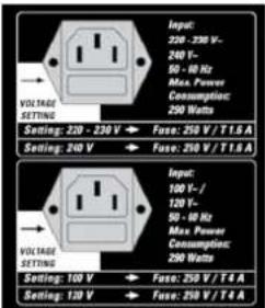
COREBLADE ships in two versions rated for 110/120V and 220
You will find the rating indicated on the housing above the mains socket. Both models offer two operating voltages that are selected using the voltage selector integrated in the mains socket. Ensure that the mains voltage matches the voltage
itratilegappearing in the voltage selector window. This value is legible when the amp is in the standard operating position; that is, sitting right side up. The upright number indicates the currently selected voltage, and the inverted number indicates the alternative voltage. Also check the fuse ratings to ensure they match the ratings indicated on the rear panel.
Voltage selection and fuse replacement may be performed by experienced service technicians only. Accordingly, the following instructions are addressed exclusively to service technicians:
- Use a small flat screwdriver to remove the voltage selector from the mains socket.
- If the fuse is defective, replace it with a fuse bearing the specified rating.
- Turn the voltage selector and insert it back into the port so that the desired mains voltage rating is legible and faces towards the top left (next to the Voltage Setting arrow).
text_image
Input: 220 - 230 V- 240 V- 50 - 10 Hz Max. Power Consumption: 250 Watts VOLUME SETTING Setting: 220 - 230 V → Fuse: 250 V / T 1.5 A Setting: 240 V → Fuse: 250 V / T 1.6 A VOLUME SETTING Setting: 150 V → Fuse: 250 V / T 4 A Setting: 120 V → Fuse: 250 V / T 4 A
text_image
100 Vdc 120 Vdc 140 Vdc 160 Vdc 200-330 Vdc 240 Vdc 140 Vdc 2,800.000COREBLADE is connected properly, but no sound is audible.
- The guitar's volume knob is turned all the way down.
• The amp is set to STANDBY. - The amp's MASTER and/or VOLUME knob is turned all the way down.
- The effects loop is active and set to SERIAL, but no effect device is connected.
- The anode fuse has blown. Check the T'SC™ display (see section 6.3.2) to ensure none of the LEDs is illuminated. Ensure that it is replaced with a fuse of the same rating.
- The fuse for the tube heating tripped (the tubes don't glow). Ensure that it is replaced with a fuse bearing the same rating.
The amp makes ringing noises when played and tends to feedback.
- One or several tubes are microphonic. Have a technician check the tubes and, if necessary, replace the defective tube with another of the same type. Read section 6.4 to learn more.
The amp sounds washed out or muddy when you switch an outboard effect on.
- The signal processor provides a wet signal that is blended with the dry source signal. Depending on the type of effect, the processor may be returning a dry signal back along with the wet signal, which causes phase cancellations when it is mixed to the dry signal in COREBLADE's parallel loop. To prevent this, set the effects loop to SERIAL or turn the dry signal all the way down on the signal processor.
10
Technical Specifications
| 10.1 Inputs | ||
| INSTRUMENT Input Jack 6.3 mm (1/4") | ||
| Type Unbalanced | ||
| Input impedance 1 M Ω | ||
| Sensitivity -40/-74/-93/-89 dBV (Clean / Drive / Ultra I / Ultra 2) | ||
| Max. input level +4 dBV | ||
| FX Return Jack 6.3 mm (1/4") | ||
| Type Unbalanced | ||
| Input impedance 48 k Ω | ||
| Sensitivity -10 dB button engaged: - 18 dB, disengaged: - 8 dB | ||
| Max. input level -10 dB button engaged: + 2 dB, disengaged + 12 dB | ||
| MIDI IN Port DIN 45 329 (7 Pins) | ||
| Power supply 15V DC max. 200mA, pin 6 = positive, pin 7 = negative | ||
| 10.2 Outputs | ||
| FX Send Jack 6.3 mm (1/4") | ||
| Type Unbalanced | ||
| Output impedance 2 k Ω | ||
| Output level + 3 dB | ||
| Max. output level -10 dB button engaged: + 2 dB, disengaged: + 12 dB | ||
| MIDI THRU | Ports | DIN 45 328 (5 pins) |
| Speaker Out | 6.3 mm (1/4") jacks | 2x 8 Ω / 1x 4 Ω, 2x 16 Ω / 1x 8 Ω, 1x 16 Ω |
| 10.3 General Electrical Data | ||
| Max. current consumption | 450 W | |
| Max. in-rush current | 21 A @ 240 V | |
| 21 A @ 220-230 V | ||
| 25 A @ 117-120 V | ||
| 26 A @ 100 V | ||
| Mains voltage tolerance range | +/- 10 % | |
| External anode fuse | 1 x T 630 mA (Anode) | |
| Internal tube heater fuse | 1 x TT 15 A | |
| Internal preamp fuse | 1 x T 1 A | |
| External mains fuse | 1 x 250 V / T 1,6 A (5x20 mm) @ 220-240 V | |
| 1 x 250 V / T 4 A (5x20 mm) @ 100-120 V | ||
| Ambient operating temperature range | 0 °C bis + 35 °C | |
| 10.4 General Mechanical Data | ||
| Dimensions (incl. corners, handles, feet) | ||
| Width | 742 mm | |
| Height | 270 mm | |
| Depth | 254 mm | |
| Weight | 18,2 kg |
Vorwort
5.8 TUBE-SAFETY-CONTROL (TSC ^™ )
text_image
Tube Matching Read-Out Insert guitar pick to read out tube matching. Please refer to the tube matching chart in the owner's manual! Power Amp Tubes Hum Balance Highus & Coulter TSC™ EL34 tubes recommended! Tube Status Control ● ● ● ● Best Blue Current! ● ● ● ● Warm Up/Standby/ Anode Fuse Malfunction: ● overcurrent no current ► Service Check before next use!5.8 TUBE-SAFETY-CONTROL (TSC")
5.8 TUBE-SAFETY-CONTROL (TSC ^™ )
text_image
Tube Matching Read-Out Insert guitar pick to read out tube matching. Please refer to the tube matching chart in the owner's manual! Power Amp Tubes Hum Balance High/Value TSC™ EL34 tubes recommended! Tube Status Control ● Best Bias Current ● Warm Up/Standby/ Anode Fuse Malfunction: ● overcurrent no current ► Service Check before next use!text_image
REVER Volume Bypass Volume Delay Feedback Time 30ms 1.4s MOD FX Intensity Type3.1 REVERB
5.8 TUBE-SAFETY-CONTROL (TSC")
text_image
Tube Matching Read-Out Insert guitar pick to read out tube matching. Please refer to the tube matching chart in the owner's manual! Power Amp Tubes Tube Status Control ● Best Bias Current A ● D ● 5 Warm Up/Standby/ Anode Fuse Hum Balance High&Value TSC™ EL34 tubes recommended! Malfunction: ● overcurrent no current ► Service Check before next use!International Inquiries:
Fax: +49 - 68 51 - 905 200
hkinternational@hughes-and-kettner.com
www.hughes-and-kettner.com