
Attax 200 - Audio Amplifier HUGHES & KETTNER - Free user manual and instructions
Find the device manual for free Attax 200 HUGHES & KETTNER in PDF.

User questions about Attax 200 HUGHES & KETTNER
0 question about this device. Answer the ones you know or ask your own.
Ask a new question about this device
Download the instructions for your Audio Amplifier in PDF format for free! Find your manual Attax 200 - HUGHES & KETTNER and take your electronic device back in hand. On this page are published all the documents necessary for the use of your device. Attax 200 by HUGHES & KETTNER.
USER MANUAL Attax 200 HUGHES & KETTNER
- Read all of these instructions!
- Save these instructions for later use!
- Follow all warnings and instructions marked on the product!
- Do not use this product near water, i.e. bathtub, sink, swimming pool, wet basement, etc.
- Do not place this product on an unstable cart, stand or table. The product may fall, causing serious damage to the product or to persons!
- Slots and openings in the cabinet and the back or bottom are provided for ventilation; to ensure reliable operation of the product and to protect it from overheating, these openings must not be blocked or covered. This product should not be placed in a built-in installation unless proper ventilation is provided.
- This product should not be placed near a source of heat such as a stove, radiator, or another heat producing amplifier.
- Use only the supplied power supply or power cord. If you are not sure of the type of power available, consult your dealer or local power company.
- Do not allow anything to rest on the power cord. Do not locate this product where persons will walk on the cord.
- Never break off the ground pin on the power supply cord.
- Power supply cords should always be handled carefully. Periodically check cords for cuts or sign of stress, especially at the plug and the point where the cord exits the unit.
- The power supply cord should be unplugged when the unit is to be unused for long periods of time.
- If this product is to be mounted in an equipment rack, rear support should be provided.
- This product should be used only with a cart or stand that is recommended by Hughes & Kettner.
- Never push objects of any kind into this product through cabinet slots as they may touch dangerous voltage points or short out parts that could result in risk of fire or electric shock. Never spill liquid of any kind on the product.
- Do not attempt to service this product yourself, as opening or removing covers may expose you to dangerous voltage points or other risks. Refer all servicing to qualified service personnel.
- Unplug this product from the wall outlet and refer servicing to qualified service personnel under the following conditions:
- When the power cord or plug is damaged or frayed.
- If liquid has been spilled into the product.
- If the product has been exposed to rain or water.
- If the product does not operate normally when the operating instructions are followed.
- If the product has been dropped or the cabinet has been damaged.
- If the product exhibits a distinct change in performance, indicating a need of service!
- Adjust only these controls that are covered by the operating instructions since improper adjustment of other controls may result in damage and will often require extensive work by a qualified technician to restore the product to normal operation.
- Exposure to extremely high noise levels may cause a permanent hearing loss.
- Individuals vary considerably in susceptibility to noise induced hearing loss, but nearly everyone will lose some hearing if exposed to sufficiently intense noise for a sufficient time. The U.S. Government's Occupational Safety and Health Administration (OSHA) has specified the following permissible noise level exposures:
| Duration Per Day In Hours | Sound LeveldBA, Slow Response |
| 8 | 90 |
| 6 | 92 |
| 4 | 95 |
| 3 | 97 |
| 2 | 100 |
| 1^1/_2 | 102 |
| 1 | 105 |
| /_3 | 110 |
^1/_4 or less 115
- According to OSHA, any exposure in excess of the above permissible limits could result in some hearing loss.
- Ear plug protectors in the ear canals or over the ears must be worn when operating this amplification system in order to prevent a permanent hearing loss if exposure is in excess of the limits as set forth above. To ensure against potentially dangerous exposure to high sound pressure levels, it is recommended that all persons exposed to equipment capable of producing high sound pressure levels such as this amplification system be protected by hearing protectors while this unit is in operation.
- Fuses: For continued protection against risk of fire, replace fuses only with the same type and ratings.
TO PREVENT THE RISK OF FIRE AND SHOCK HAZARD, DO NOT EXPOSE THIS APPLIANCE TO MOISTURE OR RAIN. DO NOT OPEN CASE; NO USER SERVICE-ABLE PARTS INSIDE. REFER SERVICING TO QUALIFIED SERVICE PERSONNEL.
PLEASE READ BEFORE USE AND KEEP FOR LATER USE!
- The unit has been built by Hughes & Kettner in accordance with IEC 6.5 and left the factory in safe working order. To maintain this condition and ensure non-risk operation, the user must follow the advice and warning comments found in the operating instructions. The unit conforms to Protection Class 1 (protectively earthed).
- HUGHES & KETTNER ONLY GUARANTEE THE SAFETY, RELIABILITY AND EFFICIENCY OF THE UNIT IF:
- Assembly, extension, re-adjustment, modifications or repairs are carried out by Hughes & Kettner or by persons authorized to do so.
- The electrical installation of the relevant area complies with the requirements of IEC (ANSI) specifications.
- The unit is used in accordance with the operating instructions.
- The unit is regularly checked and tested for electrical safety by a competent technician.
WARNING:
- If covers are opened or sections of casing are removed, except where this can be done manually, live parts can become exposed.
- If it is necessary to open the unit this must be isolated from all power sources. Please take this into account before carrying out adjustments, maintenance, repairs and before replacing parts.
- Adjustment, maintenance and repairs carried out when the unit has been opened and is still live may only be performed by specialist personnel who are authorized by the manufacturer (in accordance with VBG 4) and who are aware of the associated hazards.
- Loudspeaker outputs which have the IEC 417/5036 symbol (Diagram 1, below) can carry voltages which are hazardous if they are made contact with. Before the unit is switched on, the loudspeaker should therefore only be connected using the lead recommended by the manufacturer.
- Where possible, all plugs on connection cables must be screwed or locked onto the casing.
- Replace fuses using only those of the specified type and current rating.
- It is not permitted to use repaired fuses or to short-circuit the fuse holder.
- Never interrupt the protective conductor connection.
- Surfaces which are equipped with the „HOT" mark (Diagram 2, below), rear panels or covers with cooling slits, cooling bodies and their covers, as well as tubes and their covers are purposely designed to dissipate high temperatures and should therefore not be touched.
- High loudspeaker levels can cause permanent hearing damage. You should therefore avoid the direct vicinity of loudspeakers operating at high levels. Wear hearing protection if continuously exposed to high levels.
MAINS CONNECTION:
- The unit is designed for continuous operation.
- The set operating voltage must match the local mains supply voltage.
- Caution: The unit mains switch must be in position '0' before the mains cable is connected.
- The unit is connected to the mains via the supplied power unit or power cable.
- Power unit: Never use a damaged connection lead. Any damage must be rectified by a competent technician.
- Avoid connection to the mains supply in distributor boxes together with several other power consumers.
- The plug socket for the power supply must be positioned near the unit and must be easily accessible.
PLACE OF INSTALLATION:
- The unit should stand only on a clean, horizontal working surface.
- The unit must not be exposed to vibrations during operation.
- Keep away from moisture and dust where possible.
- Do not place the unit near water, baths, wash basins, kitchen sinks, wet areas, swimming pools or damp rooms. Do not place objects containing liquid on the unit - vases, glasses, bottles etc.
- Ensure that the unit is well ventilated.
- Any ventilation openings must never be blocked or covered. The unit must be positioned at least 20 cm away from walls. The unit may only be fitted in a rack if adequate ventilation is ensured and if the manufacturer's installation instructions are followed.
- Keep away from direct sunlight and the immediate vicinity of heating elements and radiant heaters or similar devices.
- If the unit is suddenly moved from a cold to a warm location, condensation can form inside it. This must be taken into account particularly in the case of tube units. Before switching on, wait until the unit has reached room temperature.
- Accessories: Do not place the unit on an unsteady trolley, stand, tripod, base or table. If the unit falls down, it can cause personal injury and itself become damaged. Use the unit only with the trolley, rack stand, tripod or base recommended by the manufacturer or purchased together with the unit. When selling the unit up, all the manufacturer's instructions must be followed and the setup accessories recommended by the manufacturer must be used. Any combination of unit and stand must be moved carefully. A sudden stop, excessive use of force and uneven floors can cause the combination of unit and stand to tip over.
- Additional equipment: Never use additional equipment which has not been recommended by the manufacturer as this can cause accidents.
- To protect the unit during bad weather or when left unattended for prolonged periods, the mains plug should be disconnected. This prevents the unit being damaged by lightning and power surges in the AC mains supply.
CONSEILS DE SECURITE IMPORTANTS!
PRIERE DE LIRE AVANT L'EMPLOI ET A CONSERVER POUR UTILISATION ULTERIEURE!
Congratulations and thank you for choosing the Hughes & Kettner ATTAX 200 amp!
A team of guitarists and technicians developed the ATTAX amps with a single purpose in mind: to provide you with sophisticated guitar sounds and practical features in an easy-to-handle package.
The ATTAX 200 is the ideal workhorse for discerning players who want a wealth of world-class tone and power both on stage and in the studio. The ATTAX 200 is based on the patent-applied-for TUBEMAN technology. All three channels feature authentic tube circuitry. The ATTAX 200's high-performance Current Feedback power amp delivers not only 2 x 120 watts of punch, but also the sought-after tone of a classic tube amp.
Two essential, top-quality guitar effects, STEREO ROTARY CHORUS and the ACCUTRONICS stereo reverb system, are at your disposal.
The ATTAX 200 is ready for MIDI! The MSM-1 MIDI Module is available as an option and enables you to quickly and inexpensively upgrade the amp with MIDI switching capabilities. This amp is a viable alternative to conventional rack-mounted systems.
Its logical control layout gives you immediate access to the ATTAX 200 world of sound. This manual introduces you to its many features and application options.
We wish you a lot of fun and success with your new ATTAX 200!
TABLE OF CONTENTS
BEFORE POWERIN UP 5
1.0 CHANNELS 6
2.0 JACKS AND CONTROL FEATURES
3.0 STANDARD SETUP/CABLE CONNECTIONS 8
4.0 OPERATING THE ATTAX 200
4.1 SELECTING CHANNELS AND CHORUS
4.2 THE ATTAX 200 AND SIGNAL PROCESSORS
4.3 THE ATTAX 200 AND MIDI 9
4.4 RECORDING OUTPUT 10
5.0 SERVICE AND PREVENTIVE MAINTENANCE
6.0 TROUBLESHOOTING 11
7.0 TECHNICAL SPECIFICATIONS 12
BEFORE POWERING UP...
- Check that the local current and the amp's AC power rating are identical before you plug the power cord into an AC outlet.
- Make certain air can circulate freely around the back of your amp. Proper cooling will prolong the life of your amp.
- Place the amp on a stable platform where it is not exposed to mechanical shocks and temperature extremes which may damage the amp or endanger the safety of bystanders.
- Hughes & Kettner is not liable for damages due to improper use.
1.0 CHANNELS
The tube circuitry of the ATTAX 200 is based on the innovative sound technology first popularized in the TUBEMAN. Each of the three channels drive the ECC83 twin triode tube stages differently to achieve unique sounds with markedly different characteristics.
CLEAN:
The ECC 83 preamp tube delivers classic clean sounds for rich, glassy single-note lines and crisp chord work. At higher VOLUME knob settings, the "SoftClick" circuitry produces the soft clip of a vintage tube amp. The loudest setting where the sound is still totally clean depends on the impedance of your instrument's pickups. Generally, the loudest undistorted setting for the CLEAN channel will have roughly the same volume as the CRUNCH channel at maximum gain.
CRUNCH
Blues sounds a la carte! This channel covers the entire sound spectrum from clean to overdrive. It is extremely dynamic. Its attack response enables you to control overdrive levels via your guitar's volume pot. At higher gain settings, your tone is carried by lengthy sustain, ideal for stinging blues tone with dramatic dynamics.
LEAD 1 + 2:
This channel delivers direct, in-your-face rock sounds. Switch to the LEAD 2 sound mode to get a completely different tonal character - even more bottom end, compression and sustain - in other words, the distinctive performance characteristics of contemporary tube amps, ideal for modern lead playing and heavy-duty power chord riffing.
STEREO / ROTARY CHORUS:
Warm, smooth chorus sounds featuring a deep response and shimmering harmonic overtones. You can set the RATE and DEPTH individually for the CLEAN/CRUNCH and LEAD channels, respectively. At a RATE setting of about 12 o'clock, the modulation envelope generates an effect similar to that of a rotating speaker.
STEREO REVERB
The ACCUTRONICS 3-spring reverb system is known for its high quality sound. A special circuit in the ATTAX 200 produces a stereo reverb effect that a single microphone can handle without the annoyance of phase cancellation. The reverb is located after the FX loop so you can use it for external effects and still achieve a clean reverb sound.
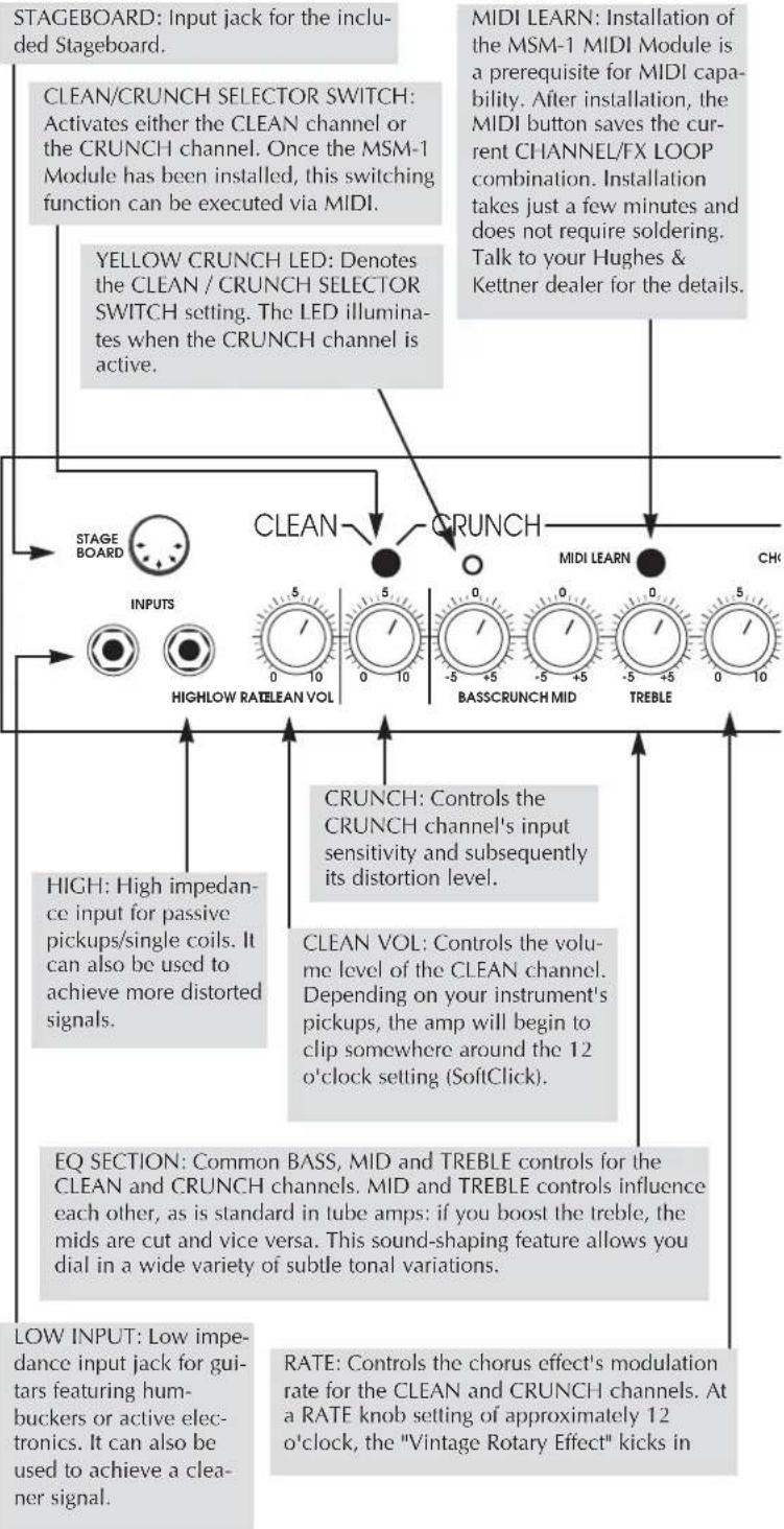
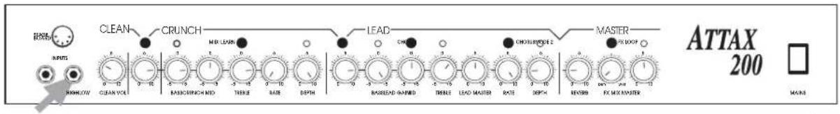
2.0 JACKS AND CONTROL FEATURES
flowchart
graph TD
    A["STAGEBOARD: Input jack for the included Stageboard."] --> B["CLEAN/CRUNCH SELECTOR SWITCH: Activates either the CLEAN channel or the CRUNCH channel. Once the MSM-1 Module has been installed, this switching function can be executed via MIDI."]
    B --> C["YELLOW CRUNCH LED: Denotes the CLEAN / CRUNCH SELECTOR SWITCH setting. The LED illuminates when the CRUNCH channel is active."]
    C --> D["STAGE BOARD INPUTS"]
    D --> E["INPUTS HIGHLOW RATELEAN VOL"]
    E --> F["CRUNCH: Controls the CRUNCH channel's input sensitivity and subsequently its distortion level."]
    F --> G["HIGH: High impedance input for passive pickups/single coils. It can also be used to achieve more distorted signals."]
    F --> H["CRUNCH: Controls the volume level of the CLEAN channel. Depending on your instrument's pickups, the amp will begin to clip somewhere around the 12 o'clock setting (SoftClick)."]
    H --> I["EQ SECTION: Common BASS, MID and TREBLE controls for the CLEAN and CRUNCH channels. MID and TREBLE controls influence each other, as is standard in tube amps: if you boost the treble, the mids are cut and vice versa. This sound-shaping feature allows you dial in a wide variety of subtle tonal variations."]
    I --> J["LOW INPUT: Low impedance input jack for guitars featuring humbuckers or active electronics. It can also be used to achieve a cleaner signal."]
    K["MIDI LEARN: Installation of the MSM-1 MIDI Module is a prerequisite for MIDI capability. After installation, the MIDI button saves the current CHANNEL/FX LOOP combination. Installation takes just a few minutes and does not require soldering. Talk to your Hughes & Kettner dealer for the details."]
    L["RATE: Controls the chorus effect's modulation rate for the CLEAN and CRUNCH channels. At a RATE knob setting of approximately 12 o'clock, the "Vintage Rotary Effect" kicks in"] --> M["HIGHLOW RATELEAN VOL"]
    M --> N["BASSCRUNCH MID"]
    N --> O["TREBLE"]
flowchart
graph TD
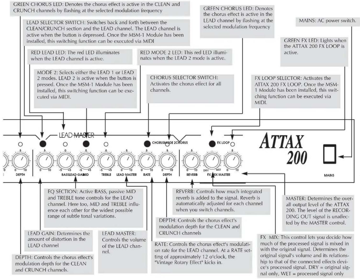
A["LEAD MASTER"] --> B["LEAD SELECTOR SWITCH: Switches back and forth between the CLEAN/CRUNCH section and the LEAD channel. The LEAD channel is active when the button is depressed. Once the MSM-1 Module has been installed, this switching function can be executed via MIDI"]
A --> C["RED MODE 2 LED: This red LED illuminates when the LEAD channel is active."]
A --> D["MODE 2: Selects either the LEAD 1 or LEAD 2 modes. LEAD 2 is active when the button is pressed. Once the MSM-1 Module has been installed, this switching function can be executed via MIDI"]
A --> E["CHORUS SELECTOR SWITCH: Activates the chorus effect for all channels."]
A --> F["CHORUS MODE 2 CHORUS"]
A --> G["FX LOOP"]
A --> H["REVERB: Controls how much integrated reverb is added to the signal. Reverb is automatically adjusted for each channel when you switch channels."]
A --> I["DEPTH: Controls the chorus effect's modulation depth for the CLEAN and CRUNCH channels."]
A --> J["EQ SECTION: Active BASS, passive MID and TREBLE tone controls for the LEAD channel. Here too, MID and TREBLE influence each other for the widest possible range of subtle tonal variations."]
A --> K["LEAD GAIN: Determines the amount of distortion in the LEAD channel"]
A --> L["LEAD MASTER: Controls the volume of the LEAD channel."]
A --> M["RATE: Controls the chorus effect's modulation rate for the LEAD channel. At a RATE setting of approximately 12 o'clock, the "Vintage Rotary Effect" kicks in."]
A --> N["MAINS: AC power switch."]
A --> O["FX LOOP SELECTOR: Activates the ATTAX 200 FX LOOP. Once the MSM-1 Module has been installed, this switching function can be executed via MIDI."]
A --> P["MASTERS: Determines the overall output level of the ATTAX 200. The level of the RECORDING OUT signal is unaffected by the MASTER control."]
A --> Q["FX MIX: This control lets you decide how much of the processed signal is mixed in with the original signal. Determines the original signal's volume and its relationship to that of the connected effects device's processed signal. DRY = original signal only, WET = processed signal only"]
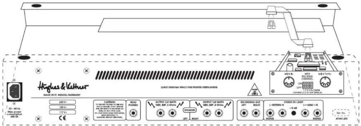
MAINS: Connect the included Euro-norm mains cord to this socket. Ensure the amp's voltage rating matches your local AC voltage rating before you plug the cord into the wall socket.
HEADPHONES: 1/4" headphone jack. In order to switch the main speaker off, unplug the speaker cable.
RECORDING OUT L/R: These output jacks can feed a mixing console or additional (stereo) power amp.
SEND: If you are using a stereo signal processor, connect these jacks to the processor's INPUT jacks. For mono operation, connect only the ATTAX 200's SEND R jack to the processor's INPUT jack.
SPEAKERS LEFT: Two 1/4" output jacks for connecting speakers to the left channel. The two jacks are wired in parallel. Ensure the overall impedance does not drop below 4 ohms for these two outputs. For the ATTAX 200 combo, you can connect an additional speaker cabinet (at least 8 ohms/60W) in parallel to the internal speaker. For the head version, you can connect one cabinet (at least 4 ohms/120W) or two 8-ohm cabinets.
SPEAKERS RIGHT: Right channel speaker output jacks.
- 10 db SWITCH: This switch allows you to reduce the signal level being sent to external effects devices. Press this switch for instrument level processors (e.g. stomp boxes).
RETURN L/R: If you are using a stereo signal processor, connect these jacks to the processor's OUTPUT jacks. For mono operation, connect the RETURN L jack only.
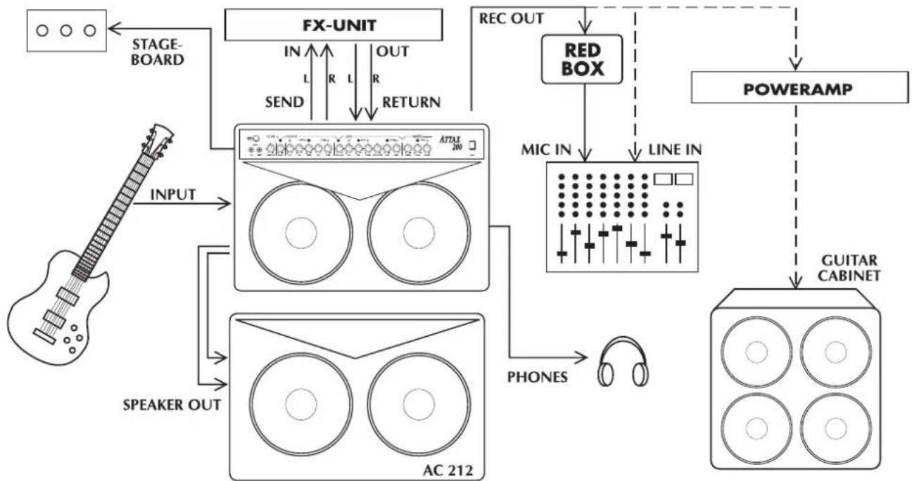
3.0 STANDARD SETUP/CABLE CONNECTIONS
flowchart
graph TD
    A["STAGE BOARD"] --> B["FX-UNIT"]
    B --> C["REC OUT"]
    C --> D["RED BOX"]
    D --> E["MIC IN"]
    E --> F["LINE IN"]
    F --> G["POWERAMP"]
    G --> H["GUITAR CABINET"]
    I["SPEAKER OUT"] --> J["AC 212"]
    K["IN L R L R"] --> B
    L["SEND"] --> B
    M["RETURN"] --> B
    N["STAGE BOARD"] --> O["INPUT"]
    P["AC 212"] --> Q["PROFESSIONAL Display"]
    R["PROFESSIONAL Display"] --> S["PROFESSIONAL Display"]
    T["PROFESSIONAL Display"] --> U["PROFESSIONAL Display"]
    V["PROFESSIONAL Display"] --> W["PROFESSIONAL Display"]
    X["PROFESSIONAL Display"] --> Y["PROFESSIONAL Display"]
    Z["PROFESSIONAL Display"] --> AA["PROFESSIONAL Display"]
    AB["PROFESSIONAL Display"] --> AC["PROFESSIONAL Display"]
    AD["PROFESSIONAL Display"] --> AE["PROFESSIONAL Display"]
    AF["PROFESSIONAL Display"] --> AG["PROFESSIONAL Display"]
    AH["PROFESSIONAL Display"] --> AI["PROFESSIONAL Display"]
    AJ["PROFESSIONAL Display"] --> AK["PROFESSIONAL Display"]
    AL["PROFESSIONAL Display"] --> AM["PROFESSIONAL Display"]
    AN["PROFESSIONAL Display"] --> AO["PROFESSIONAL Display"]
    AP["PROFESSIONAL Display"] --> AQ["PROFESSIONAL Display"]
    AR["PROFESSIONAL Display"] --> AS["PROFESSIONAL Display"]
    AT["PROFESSIONAL Display"] --> AU["PROFESSIONAL Display"]
    AV["PROFESSIONAL Display"] --> AW["PROFESSIONAL Display"]
    AX["PROFESSIONAL Display"] --> AY["PROFESSIONAL Display"]
    AZ["PROFESSIONAL Display"] --> BA["PROFESSIONAL Display"]
    BB["PROFESSIONAL Display"] --> BC["PROFESSIONAL Display"]
    BD["PROFESSIONAL Display"] --> BE["PROFESSIONAL Display"]
    BF["PROFESSIONAL Display"] --> BG["PROFESSIONAL Display"]
    BH["PROFESSIONAL Display"] --> BI["PROFESSIONAL Display"]
    BJ["PROFESSIONAL Display"] --> BK["PROFESSIONAL Display"]
    BL["PROFESSIONAL Display"] --> BM["PROFESSIONAL Display"]
    BN["PROFESSIONAL Display"] --> BO["PROFESSIONAL Display"]
    BP["PROFESSIONAL Display"] --> BQ["PROFESSIONAL Display"]
    BR["PROFESSIONAL Display"] --> BS["PROFESSIONAL Display"]
    BT["PROFESSIONAL Display"] --> BU["PROFESSIONAL Display"]
    BV["PROFESSIONAL Display"] --> BW["PROFESSIONAL Display"]
    BX["PROFESSIONAL Display"] --> BY["PROFESSIONAL Display"]
    BZ["PROFESSIONAL Display"] --> CA["PROFESSIONAL Display"]
    CB["PROFESSIONAL Display"] --> CC["PROFESSIONAL Display"]
    DD["PROFESSIONAL Display"] --> DE["PROFESSIONAL Display"]
    BEX["PROFESSIONAL Display"] --> BEX["PROFESSIONAL Display"]
    BFX["PROFESSIONAL Display"] --> BFX["PROFESSIONAL Display"]
The ATTAX 200's channels can be selected in one of three ways: via the CHANNEL SELECT switch, the included STAGEBOARD or if desired, via MIDI.
The LEAD SELECT switch has priority. To activate the CLEAN or CRUNCH channel, the LEAD channel must be switched off.
The STAGEBOARD also operates on this channel selection principle. Two red LEDs denote the current switching status. The STAGEBOARD displays the preset CLEAN/CRUNCH status at all times.
NOTE: Ensure the CLEAN/CRUNCH and LEAD SELECTOR SWITCHES on the front panel are set to OFF (not pushed in) when operating the ATTAX in the STAGEBOARD footswitching mode or MIDI switching mode. If you want to operate the ATTAX via the front panel switches only, ensure the STAGEBOARD is unplugged or switched off (LEDs are not illuminated).
Use the LEAD MODE switch to select either LEAD 1 or LEAD 2 mode. You can also select these modes via the MSM-1 MIDI Module. This switching function cannot be executed via the STAGEBOARD.
STAGEBOARD pin assignments:
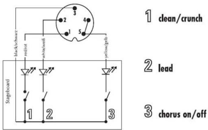
text_image
black/schwarz red/rot white/veib yellow/gefb Stageboard 1 2 3 1 2 3 clean/crunch lead chorus on/off4.2 THE ATTAX 200 AND SIGNAL PROCESSORS
The ATTAX 200 is equipped with a PARALLEL effects loop. The processed signal is mixed with the original signal so that the original signal is still audible during the brief interruptions caused by multi-effects processor switching. The FX-MIX knob controls the dry/wet mix.
NOTE: As a rule of thumb, the best method for using signal processors is to set the device so that its output is all effect, then mix the original signal with the processed signal via the FX-MIX control. This avoids the tone degradation often caused by effects devices.
Toconnect a signal processor:
- Connect the device's INPUTS to the ATTAX SEND jacks and its OUTPUTS to the ATTAX RETURN jacks.
- Activate the ATTAX FX LOOP via the included FX LOOP switch.
- Adjust the FX loop's level to the signal processor's level. Press the -10 db switch for effects devices that are designed for guitar signals. If the switch is not pushed in, the signal level remains at line level for 19" rack-mounted processors.
NOTE: It is usually more difficult to determine levels for multieffects processors featuring integrated "preamps." These do not allow direct access to the FX section, so the signal actually runs through two preamps. Effects processors without these "preamp" sections are more suitable for use in FX loops because the sound quality and dynamics are substantially better. However, if you own one of these compact devices, dial in the FX unit's most dynamic and cleanest sound. If you want to use any of the FX unit's "preamp" section sounds, we recommend you use a separate switcher/looper to switch back and forth between the two preamps. You can eliminate the ATTAX 200 preamp from the signal chain by using the return side only to route the FX processor's output signal to the ATTAX.
- Adjust the relationship between the original signal and processed signal via the FX MIX pot located on the front panel (towards DRY = more original signal, towards WET = more processed signal).
NOTE: Some signal processors cause phase cancellations that are detrimental to the overall sound. In this case, turn the FX control all the way to the right (WET). The effects loop then operates as a conventional serial loop, i.e. the volume relationship between the original and the processed signal must be adjusted at the processor. The same holds true if you want all of the signal to be processed (for instance for extreme delays and volume pedals in the FX loop).
TIP: If you choose not to connect a signal processor/effects device to the FX loop, you could connect a second instrument or a tape deck. For instance you could connect another guitar, keyboards, drum machine, tape player, etc., for rehearsals or practice sessions. When you use the FX return as a second input channel, the FX-MIX knob is used to balance the respective volumes of your guitar and the other connected signal source. Another option is open to you if you do not connect a signal processor: use the loop as an alternate MASTER volume preset. Proceed as follows:
- Activate the FX loop.
- Dial in a separate MASTER VOLUME setting via the FX MIX pot (to the left towards DRY = volume up, to the right towards
WET = volume down).
- You can switch back and forth between the two MASTER VOLUMES via the FX footswitch. If the MIDI option is installed, you can also activate the alternate MASTER VOLUME via a MIDI command.
4.3 THE ATTAX 200 AND MIDI
Once the MSM-1 MIDI Module has been installed, you can execute the majority of ATTAX 200 switching operations via MIDI. Simultaneous switching of both the ATTAX 200 and the multi-effects processor is certainly the most convenient handling option.
Installation of the MSM-1 MIDI Module:
NOTE: The MSM-1 Module must be installed by a qualified service technician. The following instructions are intended for service personnel only.
- Unplug the amp's mains cord and speaker cables.
- Remove the cover plate from the MIDI Module port on the chassis' rear panel.
- Remove the amp chassis from the wood cabinet. For the combo version, after unplugging the speaker cable, remove the four retainer screws at the top of the amp. For the head version, remove the front panel cover to access the chassis retainer screws. Make sure that you do not damage the reverb cable when you pull the chassis out.
- Insert the included MSM-1 ribbon cable connector plug in the MSM-1's socket so that the color-coded wire faces the notch on the socket. Note that the two flat cable connector plugs face away from the module in different directions. Select the plug that allows for the shortest signal path. Take care you do not bend the contact points when inserting the plug.
MSM-1 socket and indicator notch.

- Insert the MSM-1 in the module chamber and fasten it to the chassis using the four screws that you removed from the cover plate. Ensure the electronic components and the module inscriptions on the rear panel are facing right-side up.
Diagram 6: Position of the sockets.
text_image
Hughes & Vaithner MADE IN ST. WENDI/GERMANY 230 V~ 100 V~ 117 V~ CE CAUTION: TO PRINTING POWER OF 15W AND DOCKING POWER ON LAYOUT ON LAYOUT TO THE POWER OF BEANS OR NOT WITH CANE AND CONDUCTOR WITH POWER BEANS OR NOT WITH CANE SELECT DIRECTLY SWITCHER, READ PHONES OUTPUT 120 WATTS MIN. IMP. 4 Ohms SPEAKERS OUTPUT 120 WATTS MIN. IMP. 4 Ohms REC/DIERING OUT LEFT RIGHT RICH COOKING OUT LEFT RIGHT L-RETURN-R -10 dB STUDIO FX-LOOP MOND MOND MOND OFF 2.25 A CHAIN CHANNELS 2-D SEE MANUAL MEDI IN MEDI RECIPLANTS CHANNELS OFF 2.25 A CHAIN CHANNELS 2-D SEE MANUAL Max. power consumption 280 VA ATAX 200- Plug the other ribbon cable connector into the socket on the circuit board. Note the markings on the connector and ensure they face the grooved portion of the jack when you plug the connectors in.
- Ensure the connector fits snugly and the connector markings match the jack's grooved portion.
- Replace and fasten the chassis cover and insert all cable connections.
- Once you have switched the amp on, all MIDI functions should be accessible immediately. Check out all the switching functions of your amp.
NOTE: If you have connected the MSM-1 Module's polarity in reverse, then the amp's secondary fuse may trip. Generally, this should not damage the MSM-1.
Please consult the MSM-1 Operator's Manual for detailed instructions on MIDI programming and switching.
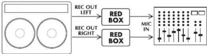
The ATTAX 200 is equipped with a recording output. This output features a filter that enhances the quality of the recording signal to such an extent that, for routine recording applications, you don't need to deal with the hassle of miking a cabinet.
However, for absolutely top-notch professional recording purposes, speaker simulation delivers an even more authentic signal. If you want to feed the ATTAX 200's signal to a mixing console in the studio or on stage, we recommend you route it through a Hughes & Kettner RED BOX. The RECORDING OUT signal path is designed so you can simply patch it directly into a RED BOX, which balances the signal and delivers sophisticated speaker simulation.
The following diagram illustrates how to connect the devices:
flowchart
graph LR
    A["Rectangular Display"] -->|REC OUT LEFT| B["RED BOX"]
    A -->|REC OUT RIGHT| C["RED BOX"]
    B --> D["MIC IN"]
    C --> D
TIP: Try mixing the RECORDING OUT signal with the signal from the cabinet microphone. This is especially effective when the stage volume is fairly low or you are playing a quiet interlude. Generally, the sound will be better than if you use just the microphone signal. Another advantage is that the RECORDING OUT signal delivers a sufficient level for the mixing console even at low volume levels.
5.0 SERVICE AND PREVENTIVE MAINTENANCE
The ATTAX 200 does not require service of any type. However, there are a few precautions you should heed to ensure your amp lasts for many years.
- Ensure all peripheral devices, cords and cables are in a state of good repair. Defective speaker cables are the most common cause of power amp failure. Poor quality cables will cause hum and undesirable noise.
- Make certain your amp's ventilation ducts are not blocked or covered. Proper cooling will prolong the life of your amp.
- Avoid mechanical shocks and exposure to extreme heat, dust and especially moisture.
- When connecting peripheral devices, always pay close attention to their specifications. Never connect speakers with impedances that are too low (insufficient ohm values). Never connect devices with high output signal levels (e.g. power amps) to your amp's input.
- Ensure you have the correct AC power rating available
before you plug in the amp. If in doubt, ask the venue's sound technician or the custodian of the building you are rehearsing in.
- Refrain from do-it-yourself repairs! Have a qualified service technician replace internal fuses.
Tube fatigue is normal after several hundred operating hours and is manifest in the form of treble loss or increased microphonics. Use a soft damp cloth to clean the exterior surface of the ATTAX 200.
6.0 TROUBLESHOOTING
1) The ATTAX will not switch on:
- The amp is not getting any AC power. Check the mains cable to see if it is connected properly.
- The mains fuse is defective. Replace the fuse with another identical fuse. If this fuse also trips, consult your Hughes & Kettner dealer.
- One of the secondary fuses has tripped because the MIDI Module was installed incorrectly (reverse polarity). Once the ribbon cable connector has been installed correctly, the secondary fuse can be replaced. Only experienced service technicians may conduct this type of repair work.
2) The ATTAX is connected properly, but no sound is audible.
- One or several GAIN and MASTER controls may be turned all the way down. Dial in a higher setting.
- The FX-MIX control is turned all the way to WET but you have not connected a processor to the FX loop. Turn the FX-MIX knob to DRY.
- A short circuit in the speaker signal chain may have tripped an internal fuse. Make sure none of the connections are shorted out and have a qualified service technician replace the fuse (identical specifications are a must).
3) The STAGEBOARD cannot activate the CLEAN/CRUNCH channels:
- The front panel selector switch is not in the "OFF" position. Set the appropriate switches to "OFF".
- The STAGEBOARD is not connected to the ATTAX. Plug it into the appropriate jack.
- The MIDI module was previously active. Briefly press the MIDI LEARN button to clear the MIDI mode.
4) The sound is thin and muddy when the effects processor is active.
- The signal processor is causing undesirable phase shifting that is being added to the original signal in the parallel loop. Turn the FX-MIX control all the way to the right (WET) to avoid phase cancellations.
5) When accessed, the RECORDING OUT jack causes annoying hum.
- An electrical or magnetic field is causing interference. Use higher-quality cables or re-arrange the cables you are using
to reduce interference to a minimum. If this still doesn't improve the situation, use a DI box.
- The grounding of the connected devices may be causing a ground loop. DO NOT SEVER THE GROUND OF THE CONNECTED DEVICES UNDER ANY CIRCUMSTANCES!
Try plugging all devices into the same socket via an AC power distributor/power strip. If this doesn't eliminate the noise, you must ensure the connection is galvanically separated by routing the signal through a DI box.
6) You have connected the RECORDING OUT jack to a mixing console and the signal is totally distorted, even when you have dialed in a clean sound.
- The RECORDING OUT signal may be overloading the mixing console's input. Reduce the mixing console's input sensitivity (GAIN). If this doesn't rectify the problem, patch the signal to the mixing console's LINE input.
7) You have connected the RECORDING OUT jack to a mixing console and the signal's volume level is way too low.
- The amp's output level is limited by an incorrectly adjusted FX processor's output level. Turn the FX processor's level up.
- The mixing console's line input is not sensitive enough. Turn up the gain. If this is still insufficient, use the microphone input (if necessary, use an adapter cable or DI box).
8) You have connected the RECORDING OUT jack to a mixing console, but you find it doesn't deliver the sound you had in mind.
- The RECORDING OUT circuit is dual-purpose. It is also designed to allow you to feed its signal to an additional power amp and cabinet. For absolutely top-notch professional recording purposes, route the signal through a Hughes & Kettner RED BOX before patching it to a mixing console.
7.0 TECHNICAL DATA
PREAMP SECTION: CLEAN, CRUNCH + LEAD tube channels
LOW INPUT: -10 dBV/ 1 M ohms
HIGH INPUT: -20 dBV/1 M ohms
FX-RETURN(l+r): -10dBV/ 0dBV/ 47 k ohms
FX-SEND(l+r): 0 dBV/-10dBV/ 1 k ohms
REC.OUT(I+r): -3 dBV/ 800 ohms
POWERAMP SECTION: 'CURRENT FEEDBACK' solid state power amp
Output Power: 2x 90 W rms into 8 ohms
2x 120 W rms into 4 ohms
PHONES: 2x 0,5 W, 600 ohms
Frequency response: 20 Hz - 50 kHz (into 2x 4 ohms)
Speakers: 2x CELESTION RockDriver Vintage, 12", 8 ohms
GENERAL FEATURES:
Voltage: 230 V\~ (European model)
117 V\~ (North American model)
100 V\~ (Japanese model)
Max. power consumption: 480 VA (into 2x 4 ohms)
Mains Fuse: slo-blo 2000 mA (230 V model)
slo-blo 4000 mA (117 V model)
slo-blo 5000 mA (100 V model)
Secondary Fuses: 2x 500 mA slo-blo (preamp)
2x 5000 mA slo-blo (power amp)
approx. 27 x 20 x 11,25"
head: 690 x 270 x 270 mm (W x H x D)
approx. 27 x 10,5 x 10,5"
Weight: combo approx. 51 Lbs./23 kg, head approx. 38 Lbs./17kg
ATTAX 200
240-WATT GUITAR AMPLIFIER
text_image
black/schwarz red/rot white/veib yellow/gelb Stageboard 1 2 3 1 clean/crunch 2 lead 3 chorus on/off4.2 DER ATTAX 200 MIT EFFEKTGERÄTEN
LOW INPUT: -10 dBV/ 1 M Ohm
HIGH INPUT: -20 dBV/1 M Ohm
FX-RETURN(l+r): -10dBV/ 0dBV/ 47 k Ohm
FX-SEND(l+r): 0 dBV/-10dBV/1 k Ohm
REC.OUT(I+r): -3 dBV/ 800 Ohm
text_image
black/schwarz red/rot white/wei6 yellow/geb Stageboard 1 2 3 1 clean/crunch 2 lead 3 chorus on/off4.2 L'ATTAX 200 ET LES PROCESSEURS D'EFFETS
LOW INPUT: -10 dBV/ 1M ohms
HI INPUT: -20 dBV/ 1M ohms
FX-RETURN: -10dBV/ 0 dB/ 47 k ohms
FX-SEND: 0 dBV/-10 dB/1 k ohms
REC.OUT: -3 dBV/ 800 ohms
SECTION ETAGE DE PUISSANCE: Ampli de puissance transistors de type
CURRENT FEEDBACK
text_image
black/schwarz red/rot white/veib yellow/gelb Stageboard 1 2 3 1 clean/crunch 2 lead 3 chorus on/off4.2 L'ATTAX 200 E I PROCESSORI DI SEGNALE
text_image
black/chwarz red/rot white/well yellow/gells Stageboard 1 2 3 1 clean/crunch 2 lead 3 chorus on/offsolid state power amplifier
The EU attestation of conformity for the manufacturer
SteinR
• American clean • 60's crunch
(additional warm chorus)
• British lead 1 • modern lead 2
(additional "rotary" - sound)
text_image
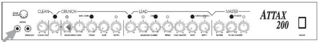
BEET INPUTS HRESHLOW CLEAN VOLT CRUNCH MIL LEAVN LEAD COLD CHORAGE MASTER MAX LOOP ATTAX 200 MAKSfor Single Coil Guitar:
• American clean • British crunch
(additional warm chorus)
• British lead 1 • modern lead 2
(additional "rotary" - sound)
text_image
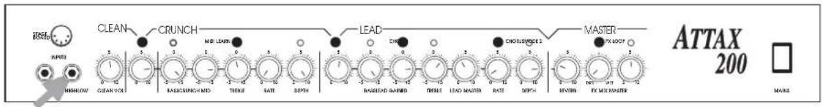
STAGE BOARD INPUT HORNLOW CLEAN VOLT CLEAN CRUNCH MIL LEAFS LEAD CH assistant/ORDER 2 MASSER ATTAX 200 MAINSfor Humbucker Guitar:
- hard funk clear • "stones" crunch
(additional warm chorus)
• British solo 1 • British solo 2
(additional warm chorus)
text_image
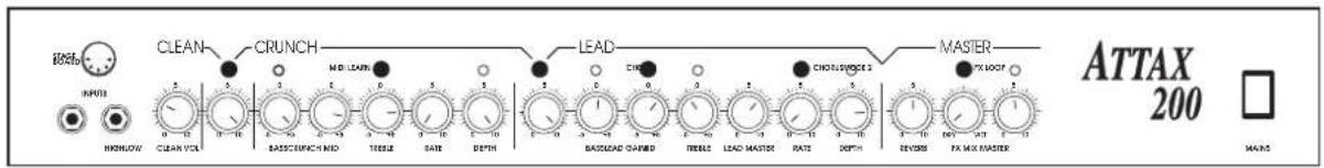
STAGE BOADS INPUTS HIGHLIGHT CLEAN CRUNCH MIDI LEARN LEAD CORN CH assistant/ORDER 2 MASTER FX LOOP ATTAX 200 MAINfor Single Coil Guitar:
- "classic strat setup"
(with additional chorus)
text_image
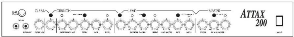
KON INPUT MASHLOW CLEAN CRUNCH MIL LEARN LEAD CHINESE CHINESE 2 MASTER FX LOOP ATTAX 200 MAINSfor "pickup mix":
- "fat" clean • L.A. crunch
(additional chorus)
• high gain 1 • high gain 2
(additional chorus)
text_image
HORN INPUTS HORNLOW CLEAN VOLT CRUNCH MIL LEAVS LEAD CINIC CHICKLECHECK 5 MASTER MAX LOCK BASILEAD CLAUDID FIRKELD LEAD MASTER RATE DEPTH EVEGET FX MAX MASTER ATTAX 200 MAINSfor your own sound setup:
•
text_image
STAGE BOARD INPUT HINDUAVA CLEAN CRUNCH MIL LEARN LEAD CHINESE CHIKELSWICE 3 MASTER TX CLK7 ATTAX 200 MAINSHughes & Kettner® TECHNOLOGY OF TONE
ANDORRA
MUSICAL ANDORRA, Sant Julia de Loria
AUSTRIA
JOHN HORNBY SKEWES & Co Ltd., Garforth, Leeds LS 25 2 HR
USA
HUGHES & KETTNER Inc., Mt Prospect, IL 60056