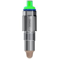
408401 - Measuring equipment Jumo - Free user manual and instructions
Find the device manual for free 408401 Jumo in PDF.


| Product type | Capacitive level detector |
| Brand | Jumo |
| Model | 408401 |
| Dimensions (device) | Diameter 25 mm, length 102 mm (excluding thread) |
| Weight | Approx. 60 g (G1/2" version with M12 connector) |
| Power supply | 9.6 to 36 V DC (SELV); Ex i version: 9.6 to 30 V DC; max. power 15 W |
| Outputs | 2 switching outputs PNP/NPN/push-pull, current ≤200 mA per output |
| Interface | IO-Link version 1.1, COM 3 (230.4 kBaud) |
| Main functions | Limit level measurement, media detection, Teach-in function, hysteresis/window, time delay, PWM modulation, autocalibration, pollution detection |
| Process temperature range | -40 to +115 °C (standard), up to +200 °C for version with sliding connection |
| Process pressure | -1 to +60 bar |
| Protection rating | With M12 connector: IP67; with cable: IP69 |
| Materials in contact with media | PEEK, stainless steel 316L, FKM/FPM |
| Mounting | Any position, tightening torque 5-10 Nm (unless otherwise specified) |
| Maintenance and cleaning | Maintenance-free; cleaning possible with damp cloth or compressed air <6 bar; avoid sharp objects |
| Safety | ATEX, IECEx, intrinsic safety [Ex i], overvoltage category II, pollution degree 2 |
| Accessories | M12 cables, Teach magnet, weld-on adapters, adapters, IO-Link Master |
| General information | Operating manual included; qualified personnel required; store dry and dust-free |
Frequently Asked Questions - 408401 Jumo
User questions about 408401 Jumo
0 question about this device. Answer the ones you know or ask your own.
Ask a new question about this device
Download the instructions for your Measuring equipment in PDF format for free! Find your manual 408401 - Jumo and take your electronic device back in hand. On this page are published all the documents necessary for the use of your device. 408401 by Jumo.
USER MANUAL 408401 Jumo
natural_image
Close-up of a metallic JUMO connector with threaded shaft and green/NYB connectors (no text or symbols on body)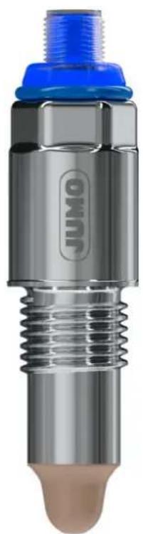
natural_image
Close-up of a Jumo mechanical component with blue threaded cap and threaded shaft (no visible text or symbols)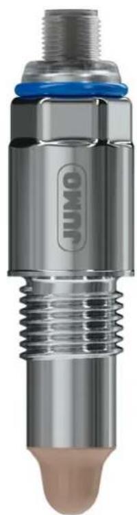
natural_image
Close-up of a JUMO engine component with threaded shaft and blue cap (no visible text or symbols beyond branding)Betriebsanleitung
Operating Manual
V1.00/DE-EN-FR-ES/00768300/2023-08-24
JUMO ZELOS
natural_image
Product comparison of JUMO engine components, showing a cylindrical tool and three metallic cylindrical plugs with blue and green connectors (no text or symbols visible)Betriebsanleitung
qr-408401-de.jumo.info
7 Installation....28
natural_image
Three technical illustrations of a DMMI engine plug assembly with no visible text or symbolsnatural_image
Cross-sectional illustration of a cylindrical container with liquid and a green cap, no text or symbols present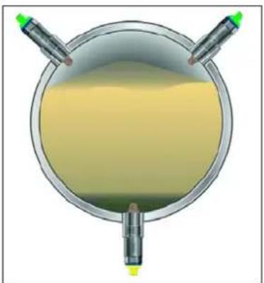
natural_image
Top-down diagram of a circular container with yellow liquid and two green test tubes, no text or symbols present.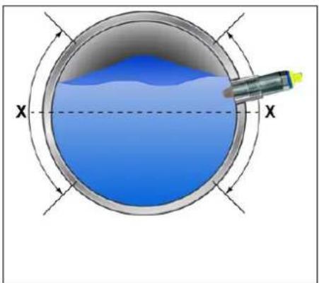
natural_image
Cross-sectional diagram of a circular container with blue liquid and a probe inserted, labeled X (no text or symbols beyond labels)https://ioddfinder.io-link.com/
line
| Time Segment | SP | rP | | ------------ | ------ | ------ | | Start | Low | Low | | Peak | High | High | | Mid | Medium | Medium | | End | Low | Low |36039 Fulda, Germany
Telefon: +49 661 6003-715
Telefax: +49 661 6003-606
E-Mail: mail@jumo.net
Internet: www.jumo.net
Lieferadresse:
Mackenrodtstraße 14
36039 Fulda, Germany
Postadresse:
36035 Fulda, Germany
8712 Stäfa, Switzerland
Telefon: +41 44 928 24 44
Telefax: +41 44 928 24 48
E-Mail: info@jumo.ch
Series of capacitive level switches
natural_image
Close-up of a metallic JUMO sensor component with threaded shaft and green/NYB connectors (no text or symbols on body)
natural_image
Close-up of a JUMO mechanical component with blue threaded cap and threaded shaft (no visible text or symbols)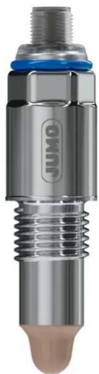
natural_image
Close-up of a JUMO engine component with threaded shaft and blue cap (no visible text or symbols beyond branding)Operating Manual
JUMO
40840100T90Z000K000
EN/2023-08-24
Further information and downloads

qr-408401-en.jumo.info
1 About this documentation ....5
1.1 Purpose....5
1.2 Target group 5
1.3 Definition of terms....5
1.4 Symbols 5
2 Safety 6
2.1 Intended use....6
2.2 Qualification of personnel 6
2.3 Risk assessment....6
2.4 Hot surface 7
2.5 Hazardous materials....7
2.6 Mechanical load 7
2.7 Hybrid mixtures....7
2.8 Transport and storage damage....7
3 Description....8
3.1 Structure....8
3.2 Function 9
3.3 Nameplate....10
3.4 Scope of delivery 11
4 Technical data ....12
4.1 Electrical data....12
4.2 Inputs 12
4.3 Outputs....12
4.4 Interface 13
4.5 Display 13
4.6 Environmental influences 13
4.7 Mechanical features 14
4.8 Dimensions....15
4.8.1 Device....15
4.8.2 Process connections....16
4.8.3 Cable....18
5 Mounting ....19
6 Electrical connection ..... 22
6.1 Connection elements ..... 25
6.1.1 Terminal assignment....25
6.2 Connection examples....26
Table of contents
7 Installation....28
7.1 Functions .....28
7.1.1 Structure of the operating menu ..... 28
7.1.2 Preparation and structure of IO-Link communication .....28
7.1.3 Teach-In function....29
7.1.4 Switching point and switching function 30
7.1.5 Window function, media detection, and media differentiation....32
7.1.6 Switching delay....33
7.1.7 Pulse-width modulation....33
7.1.8 Detection of pollution degree 34
7.1.9 Auto-calibration....34
8 Parameterization....35
9 Troubleshooting ....39
9.1 Diagnostic events 41
10 Maintenance and cleaning ....43
11 Shutdown....44
11.1 Dismounting 44
11.2 Decontamination....44
11.3 Returns 44
11.4 Disposal 44
12 Accessories....45
1.1 Purpose
This documentation is part of the device and includes all information to ensure that it is used safely and as intended across all phases of the product lifecycle.
If you do not follow the documentation and safety information, this may result in risk to life and damage to property due to improper use.
- Read and follow the documentation and the safety information and warnings.
- Store the document in its entirety, in an easily accessible location, and so that it can be read in full at all times.
- Contact the manufacturer if you have any questions about the device and documentation.
1.2 Target group
This documentation is intended to be used by personnel trained in electrical, mechanical, and plant engineering across all phases of the product lifecycle.
1.3 Definition of terms
| Use in document Definition | |
| Device, product Capacitive level switch | |
| Medium Liquids or solids |
1.4 Symbols

WARNING!
The signal word "WARNING" indicates an imminent danger.
Non-observance can lead to death or serious injury.
The instructions in the warning notice must be observed and followed!
NOTICE!
The signal word "NOTICE" indicates possible damage to property.
Non-observance can lead to damage to devices, systems or the environment.
▶ Observe the instructions in the note for avoiding damage!

REFERENCE!
This symbol refers to further information in other sections, chapters, or other manuals.
2 Safety
2.1 Intended use
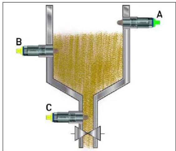
The capacitive level switch measures the point level of solid and liquid media in applications with requirements for overfill and dry run protection and can also be used for media detection, e.g. in separation and cleaning processes.
The device is suitable for installation in pressurized tanks, pipelines, containers, in hygienic areas and as part of overfill protection systems according to WHG and can be used in explosion-proof areas.
Container for liquids Container for bulk material
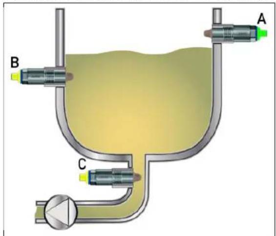
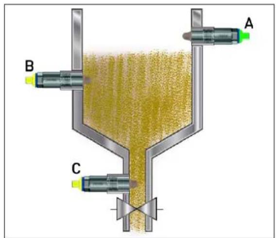
A Overfill safeguard, full indicator A Overfill safeguard, full indicator
B Process limit level B Process limit level
C Dry-run protection, empty indicator
C Dry-run protection, empty indicator
When connecting to intrinsically safe electrical circuits, the intrinsically safe version of the device [Ex i] fulfils the requirements for explosion group II of categories 1 G and 1 D, as well as 2 G and 2 D. It is therefore suitable for use in the potentially explosive area of zone 0, 1, and 2 for gas (G) and zone 20, 21, and 22 for dust (D). Here, a certified, intrinsically safe isolation amplifier [Ex ia] must be used.
The Ex approval becomes null and void if the device is used contrary to its intended use or if the safety requirements in this operating manual are not complied with.
The operating manual is part of the device. The device is only intended for use according to this operating manual.
2.2 Qualification of personnel
The personnel deployed must meet the following requirements in all phases of the product lifecycle:
- Trained electrical, mechanical, and plant engineering personnel.
- Members of personnel are familiar with this documentation and the safety information and warnings it contains.
2.3 Risk assessment
For explosion-proof versions, the operator must create the Ex-protection document for the system and carry out the zoning and risk assessment (e.g. based on ATEX 0137).
2.4 Hot surface
Hot media may result in the device surfaces becoming hot and presenting a risk of injury.
- Allow the device and plant to cool down.
- Wear suitable protective equipment.
- If required, install contact protection.
2.5 Hazardous materials
Using hazardous materials as a medium may result in abrasive and corrosive damage to components of the product that come into contact with the medium. The medium may leak and present a fire hazard and a risk to health.
Carry out a risk assessment taking into consideration the safety data sheet for the relevant hazardous substance for mounting, operation, maintenance, cleaning, and disposal:
- Comparison and systematic checking of the durability of the components of the product that come into contact with the medium and the admissible environmental influences.
- Assessment of the risk to people and the environment.
- Assessment of the fire hazard due to the product materials, the admissible environmental influences, and the voltage supply.
2.6 Mechanical load
Mechanical load on the device and process connections can lead to leaks.
- Do not place the device and the process connections under mechanical strain.
- Systematically check that the process connections are leak-tight.
2.7 Hybrid mixtures
Hybrid mixtures are explosive mixtures of flammable gases, vapors, or mists with flammable dusts. In particular, equipment used in potentially explosive areas where hybrid mixtures are present must be checked. The operator is responsible for checking that the equipment is suitable for such uses.
2.8 Transport and storage damage
The device can be damaged if it is insufficiently protected during transport and/or improperly stored.
- Transport the device protected from moisture and dirt in shockproof packaging.
• Also comply with the admissible storage temperatures while the device is being transported. - Protect all electrical and mechanical connections from damage.
- Store the device in a dry and dust-free environment.
- Observe the device storage temperature range.
3 Description
3.1 Structure
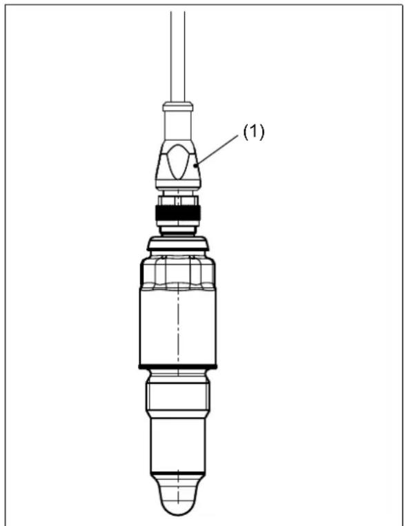
1 Connecting cable 1 M12 plug connector, 4-pole
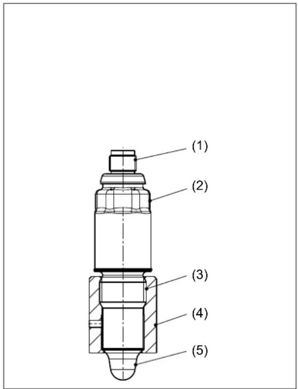
2 H o u s i n g
3 Process connection
4 Welding socket (accessories)
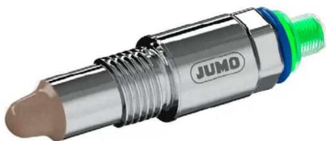
5 PEEK tip
3.2 Function
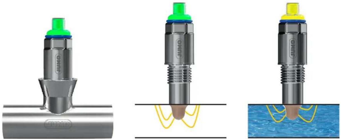
The device emits an electric field from the PEEK tip. As the medium approaches, the capacitance of the capacitor is changed in the electric field. The capacitor is formed by the PEEK tip and the housing or the vessel or pipe wall. The medium must have a minimum conductivity (dielectricity, permittivity [εr]). The change in the electric field is detected by the electronics of the device, processed further and passed on as an output signal or switching signal, e.g. to a PLC.
natural_image
Three technical illustrations of a mechanical component under different conditions: before, after, and after water displacement (no text or symbols present)Fig. 3-1 Schematic representation of the change in capacitance with media detection
3 Description
3.3 Nameplate
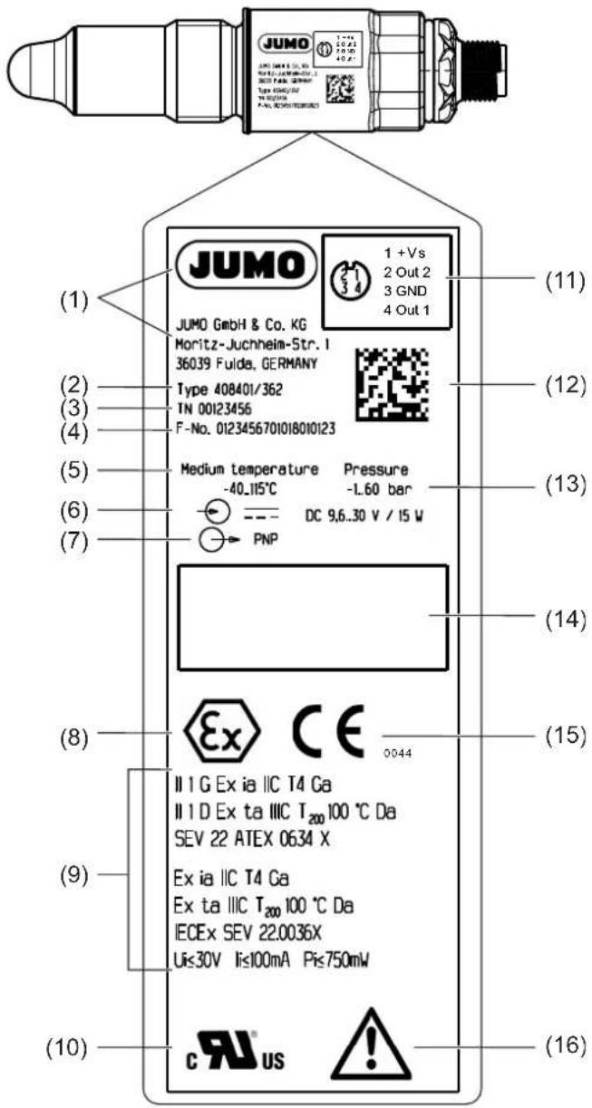
1 Manufacturer 9 Ex details
2 Type 10 UL marking
3 Part number (TN) 11 Pin assignment
4 Fabrication number (F-No.) 12 DMC code
5 Medium temperature 13 Pressure range
6 Input 14 TAG number
7 Output, voltage supply 15 EU marking
8 Ex marking 16 Read the operating manual!
3.4 Scope of delivery
| Device in the ordered version |
| Operating manual |
4.1 Electrical data
| Voltage supply DC 24 V SELVPNP, NPN, push-pullIO - Link DC 18 to 32 VExplosion protection Ex i | DC 9.6 to 36 VDC 9.6 to 30 V |
| Current consumptionaIdle mode 0.45 WSwitch operation with 2 outputs 15 WIO-Link operation 0.5 WProtection class 3Overvoltage categoryIIPollution degree2 | |
| Electrical connectionConnection elements | M12 plug connector |
| Connecting cableTemperature resistance | ≥ 90 °C |
| Electrical safetyRequirements | DIN EN 61010-1:2023The device must be equipped with an electrical circuit that meets the requirements with regard to "Limited-energy circuits". |
a The device labeling indicates a maximum power consumption in switching mode with 2 outputs including self-consumption. The actual power consumption depends on the connected load.
4.2 Inputs
| Hysteresis | ±1 mm |
| Repeatability | ±1 mm |
| Switch-on delay | < 2 s, during this time the switching outputs are blocked |
| Switching delayWhen the sensor is coveredWhen the sensor is uncovered | Adjustable 0.3 to 60 s0.5 s1 s |
| Filter time constant | Adjustable 0 to 100 s |
4.3 Outputs
| NumberFor IO-Link operationFor switching operationWith PNP, NPN, push-pull | 1 (output signal according to IO-Link communication standard version 1.1)2 (SIO mode; SIO = standard IO)2 |
| Configuration options | Hysteresis or window function, switching function, NC contact or NO contact, output p-switching (PNP) or n-switching (NPN), switch-on and switch-off delay, pulse-width modulation (PWM), pollution degree detection, wet test with medium |
| Pulse-width modulation (PWM)Period duration adjustableMark-to-space ratio | 50 to 1000 ms0 to 100 % |
| Switching current | ≤ 200 mA per output |
| Voltage drop at switching transistor | ≤ 1 V |
| Short-circuit resistance Yes (clocked) | |
| Reverse voltage protection Yes | |
| Current limiting Yes | |
4.4 Interface
IO-Link
| Communication | Via end device with IO-Link master and device description file (IODD) |
| Communication interface IO-Link device V 1.1 | |
| Data transfer rate (baud rate) COM3 | (230.4 kBaud) |
| Max. cable length 20 m, unshielded | |
| Min. cycle time 0.7 ms | |
| Function | Transfer of process data, configuration data, and device information |
| Profiles | Common Profile, Smart Sensor Profile, Firmware Update Profile |
| IO Device Description (IODD) | Depending on the ordered operating temperature range; available on the manufacturer's website https://en.jumo.de or at www.ioddfinder.io-link.com |
| Menu navigation | According to VDMA 24574-4 |
4.5 Display
| Color display | According to NE107, IO-Link, customer-specific |
| Brightness | 4 levels (configurable) |
| Self-diagnosis/self-monitoring | According to NE107 and VDI/VDE 2650 |
4.6 Environmental influences
| Resistance to climatic conditionsOperationStorage | 100 % relative humidity including condensation on the device outer case90 % relative humidity without condensation |
| Ambient temperatureCableRound plug M12 × 1 | -40 to +80 °C (fixed), -25 to +80 °C (movable)-40 to +85 °C |
| Storage temperature | -40 to +80 °C |
| Process temperatureParts in contact with the medium | -40 to 115 °C (standard), <1 h/d to 135 °C and T_amb <50 °C-40 to +200 °C (for versions with sliding connection) |
| Process pressure | -1 to +60 bar |
| Protection typeCableM12 plug connector | DIN EN 60529IP69IP67 |
| Max. site altitude | 5300 m above sea level |
4 Technical data
| Electromagnetic compatibility (EMC)Interference emissionIn metallic containers, pipes Class B ^a In plastic containers, plastic pipesInterference immunityIn metallic containers, pipes Industrial pressureIn plastic containers, plastic pipes | DIN EN 61326-1:2022Class A^b Ustrial requirementDomestic requirement |
| Vibration resistanceEndurance limitShock resistance | IEC 60068-2-6, DIN EN 61373, DIN EN 50155, category 1 B4 g at 25 to 100 Hz3 g (vertical) or 5 g (transverse and longitudinal) for 30 ms |
| Operating location according to UL approval | Indoors |
a The product is suitable for industrial use as well as for households and small businesses.
^b The product is only suitable for industrial use.
4.7 Mechanical features
| MaterialsParts in contact with the mediumProcess connectionSliding connection 360, 361 PEEK, FKM/FPM, stainless steel 316 LParts not in contact with the mediumHousing Stainless steel 316 LConnection cable PUR | PEEK (depending on sealing concept stainless steel 316 L) |
| Surface roughness R | _a ≤ 0.8 m |
| Cable bending radiusFixedMovable | r ≥ 21 mmr ≥ 42 mm |
| Installation position | Any |
| Weight | 60 g for G1/2" with M12 plug connector |
4.8 Dimensions
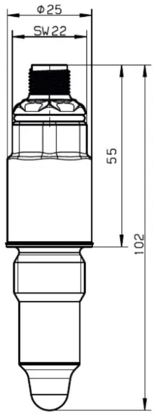
4.8.1 Device
Electrical connection 036 with M12 plug connector
4 Technical data
4.8.2 Process connections
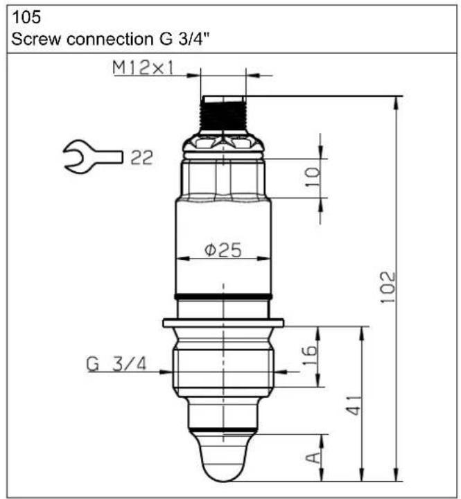
A Immersion depth, PEEK tip 12.5 mm
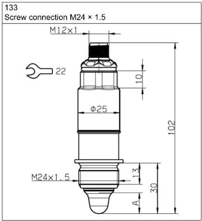
A Immersion depth, PEEK tip 12.5 mm
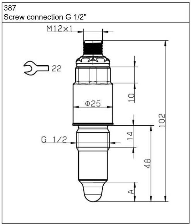
A Immersion depth, PEEK tip 12.5 mm
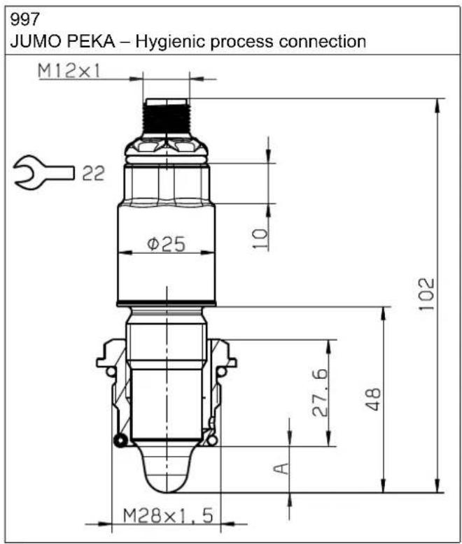
A Immersion depth, PEEK tip 12.5 mm
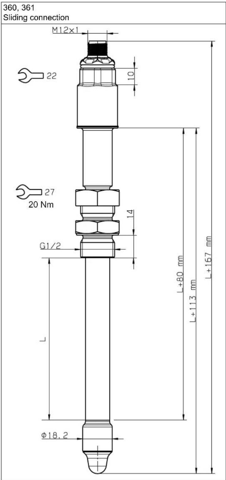
L Length 100 mm or 250 mm
4 Technical data
4.8.3 Cable
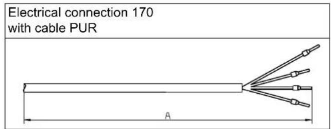
A Cable length, see order details

WARNING!
Risk of poisoning and suffocation due to the leakage of corrosive and toxic media
When working on containers or tanks, media may leak that could result in poisoning or asphyxiation.
▶ Only perform work on containers or tanks using suitable protective measures (e.g. wearing respiratory masks, breathing devices or protective clothing, discharging corrosive, toxic gases).
▶ Observe the relevant legal regulations and instructions from the company in potentially explosive areas.
Requirements:
- The system has been de-energized and secured against being switched on again.
• The device is media-free.
Aids Hexagon wrench
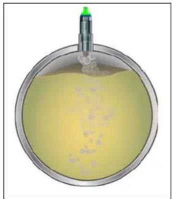
The device can be installed in any position. Depending on the application, air pockets may cause cavities for horizontal pipes in the upper pipe area. Depending on the application, deposits may settle on the lower pipe area over time. Side mounting is recommended for these cases.
natural_image
Cross-sectional illustration of a container with liquid and a green cap (no text or symbols)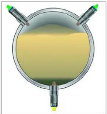
natural_image
Top-down view of a circular container with yellow liquid and two green test tubes, no text or symbols visible.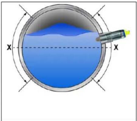
natural_image
Cross-sectional diagram of a circular container with liquid and a probe inserted, showing directional arrows (no text or symbols)Select the installation location such that no disturbing influences, such as due to inlets, agitators, may arise (e.g. filling process with undesirable incorrect measurements).
Observe the requirements below for devices with the EHEDG and/or 3A standard:
- All components of the measuring point are 3A/EHEDG-compliant.
- The installation position enables self-drainage/self-emptying of the device and detection of leakages, see figure below.
- The leakage detection in the process connection is visible after mounting and points vertically downward.
- Welded connections in contact with the medium have a surface roughness of R_a ≤ 0.8 m .
- Welding sockets are welded front-flush with the inside of the container or the pipe (compliance with welding standard AWS D18.3).
- Cavity-free installation has been taken into account in order the measuring point is completely covered with cleaning agent during cleaning.
5 Mounting
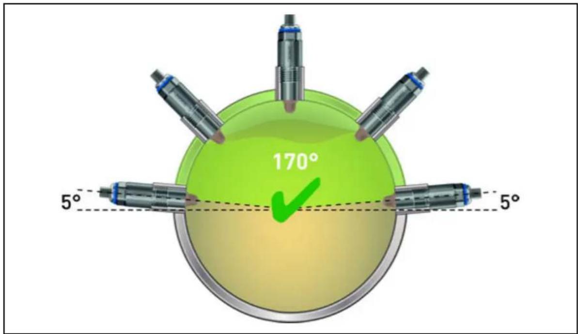
Fig. 5-1 Self-emptying
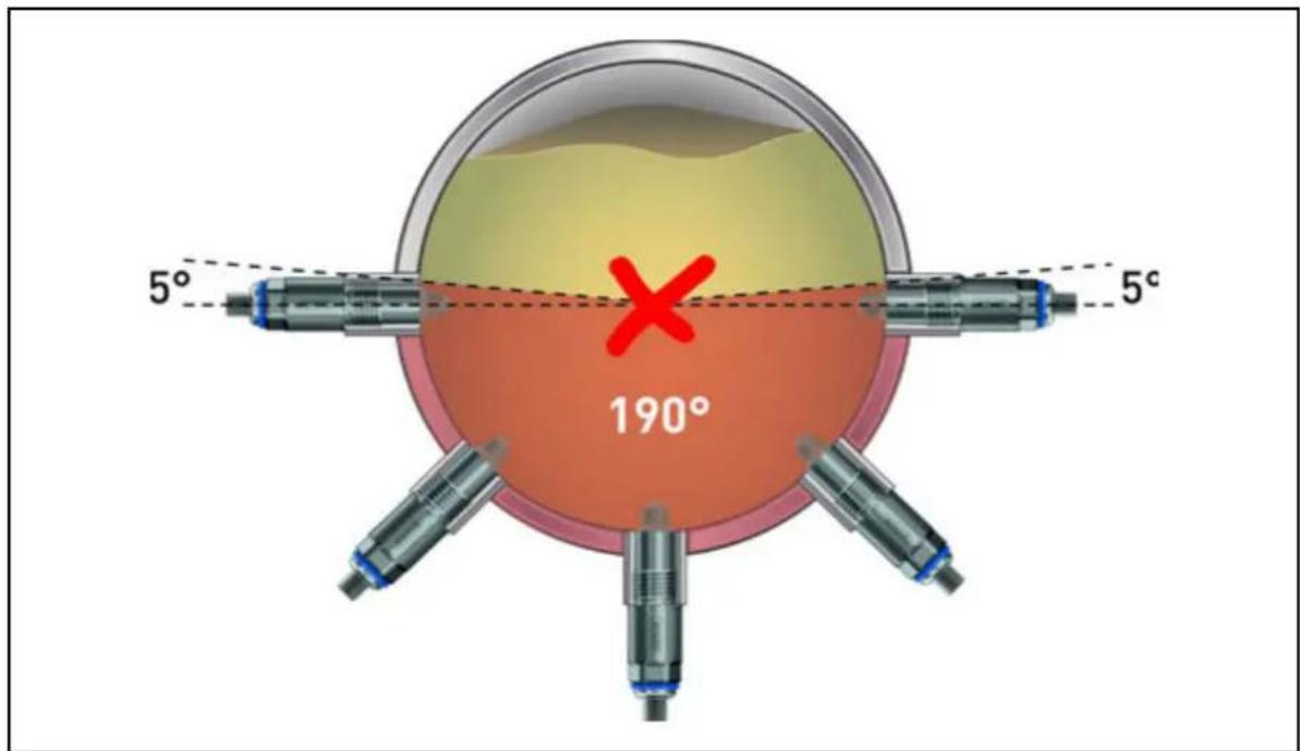
Fig. 5-2 No self-emptying possible
Take into account metallic or non-metallic installation situation according to EMC specifications.
→ chapter 4.6 "Environmental influences", Page 13
During mounting, the user should select the tightening torque, taking into account the following data:
- Relevant process connection
- Material pairing between process connection and container material
• Lubrication (for hygienic variants, e.g. NSF H1 or FDA 21 CFR 178.3570) - Se a l
• Environmental influences (e.g. pressure, temperature)
The technical regulation VDI 2230 provides assistance here.
Typically, the tightening torque is 5 to 10 Nm. If ordered from the accessories, the tightening torque is 10 Nm for the supplied welding sockets.
The sealing surfaces between the tank, container, or pipe and the device must be clean and free from mechanical damage.
With process connection G 1/2", the device is sealed elastomer-free, without an additional seal in the area of the device tip. If sealing is not provided via the PEEK tip, sealing tape (e.g. PTFE) in the area of the thread is recommended.
The sealing effect of the device tip is optimum at first mounting. Mounting for test purposes is not necessary.
NOTICE!
Damage to the device tip due to improper handling.
The device tip may be damaged during mounting or re-installation.
▶ Check the device tip for notches or grooves.
▶ Only use the hexagon wrench for screwing in.
The connection is made in a zero-current state, taking into consideration DIN VDE 0100 "Erection of low voltage installations" or the respective national regulations (e.g. based on IEC 60364).
The operator is responsible for the design of the corresponding connection line.
The cables installed on the device are designed for fixed installation.
Fuse the load circuit to the maximum admissible switching current in order to prevent destruction of the device due to an external short circuit.
⇒ chapter 4 "Technical data", Page 12
Observe the connection examples for capacitive and inductive loads.
→ chapter 6.2 "Connection examples", Page 26
Unless otherwise specified, the device must be grounded through the process connection or the housing.
Depending on the selected electrical connection on the device, seal the counterpiece or the cable passage in order to achieve the protection type.

WARNING!
Risk of injury and material damage due to faulty connection
A faulty connection, e.g. high short circuit current via the output, may destroy the device and lead to device malfunctions and injuries.
▶ Connect device according to connection diagram.
▶ Observe the necessary safety regulations.
Use a stabilized power supply unit or, in the case of a potentially explosive application, an intrinsically safe isolation amplifier [Ex i].
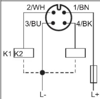
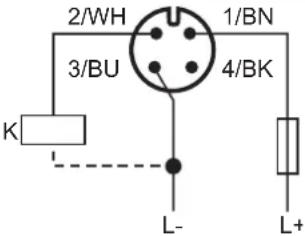
Using 2-channel evaluation, the device function can be monitored in addition to point level measurement, depending on the variant ordered. When connecting, both outputs have opposite states in fault-free operation. The anti-valent electrical circuit can be used to identify malfunctions in the device or be used in the event of line break, as both outputs switch off on the voltage side.
| Connection for function monitoring using anti-valence | Status display according to NE107 (Reference to output 1, lit up continuously- ly) | IO-Link (SIO mode with Werkseinstellung) | ||
 | Sensor covered | 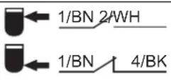 | Yellow Yellow | |
| Sensor free | 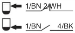 | Green Green | ||
| Malfunc-tion | 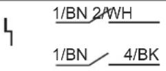 | Red Red | ||
1 Voltage supply +
2 Output 2 (OUT2), e.g. PNP
3 Voltage supply -
4 Output 1 (OUT1), e.g. IO-Link in SIO mode
K1/K2 External load
For variants with an IO-Link interface, communication is on C/Q and switch operation on Q2. The default settings can be changed via IO-Link depending on the application.
| Electrical connection | IO-Link with one switching output | |
M12 connector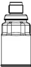 | 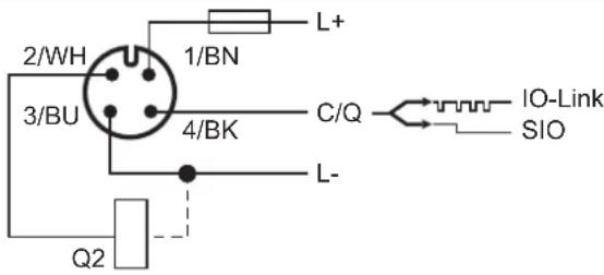 | |
1 Voltage supply +
2 Output 2 (OUT2), e.g. PNP
3 Voltage supply -
4 Output 1 (OUT1), IO-Link communication, or SIO mode
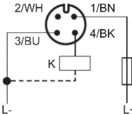
| Electrical connection | Operating mode (SIO mode with default setting) | |||
M12 connector | MAX MIN | |||
 |  | |||
 | Yellow,lit up continuously |  | Green,lit up continuously | |
 | Green,lit up continuously |  | Yellow,lit up continuously | |
1 Voltage supply +
2 Output 2 (OUT2), e.g. PNP
3 Voltage supply -
4 Output 1 (OUT1), IO-Link communication, or SIO mode
K External load
The voltage supply is switched on.
Depending on the configured status display, the functions below are signaled. The priority of the signaling has the output 1 (OUT1).
| Status display according to NE107 Description | |
| Green, lit up continuously | Supply and operation, device is ready for operation |
| Blue, lit up continuously Maintenance required, e.g. clean PEEK tip | |
| Yellow, lit up continuously Device is covered by liquid | |
| Red, flashing Outside the specification or functional check, error can be remedied, e.g. temperature range exceeded or incorrect wiring | |
| Red, lit up continuously | Malfunction and/or device failure, error cannot be remedied, e.g. electronic damage |
| Status display according to IO-Link Description | |
| Green, lit up continuously Device is ready for operation, SIO mode | |
| Green, flashing 10111011101110a | Active communication |
| Green, flashing 0101010001010a | Device search (identification of the device) |
| Yellow, lit up continuously | Device is covered by liquid, output 1 switched |
| Red, lit up continuously Malfunction and/or device failure | |
a 1 = 900 ms lit up, 0 = 100 ms off
WARNING!
Risk of injury and material damage due to faulty system states
When filling the container, the tank, or the pipe, uncontrolled system states may be triggered and result in injuries and material damage.
▶ The plant must be in an error-free state.
▶ Check that the output signal is functioning as intended.

6.1 Connection elements
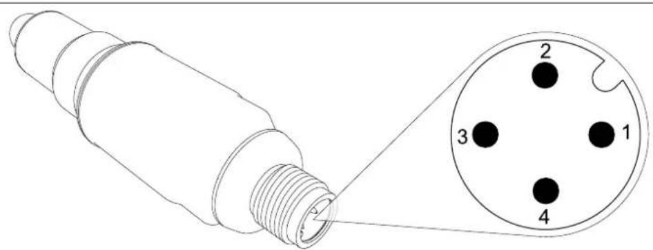
Device M12 plug connector
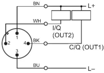
6.1.1 Terminal assignment
M12 plug connector
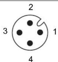
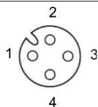
Device Connecting cable
| Designation Description Assignment | a | |
| IO-Link L+ 1 BN (brown) | ||
| L- 3 BU (blue) | ||
| I/Q = OUT2 2 WH (white) | ||
| C/Q = IO-Link 4 BK (black) | ||
| PNP L+ 1 BN (brown) | ||
| L- 3 BU (blue) | ||
| OUT2 2 WH (white) | ||
| OUT1 4 BK (black) | ||
| NPN | L+ 1 BN (brown) | |
| L- 3 BU (blue) | ||
| OUT2 2 WH (white) | ||
| OUT1 4 BK (black) | ||
| push-pull | L+ 1 BN (brown) | |
| L- 3 BU (blue) | ||
| OUT2 2 WH (white) | ||
| OUT1 4 BK (black) |
^a The color coding is only valid for A-coded standard cables!
6 Electrical connection
If connected to a certified intrinsically safe electrical circuit [Ex i], the following values are given.
| Output signal M | Max. voltage Ui in V in mA in mW in μH in nF | Max. current Ui in μH in nF | Max. power Pi | Inner inductance Inner capacitance |
| PNP ≤ 30 ≤ 100 | ≤ 750 57 35 version | For cable version 0,2 nF/m add connecting cable | ||
| NPN For cable push-pull |
6.2 Connection examples
Standard
| IO-Link operation with 1 switching output | Switch operation with 2 switching outputs | |
| p-switching (PNP) p-switching (PNP) | ||
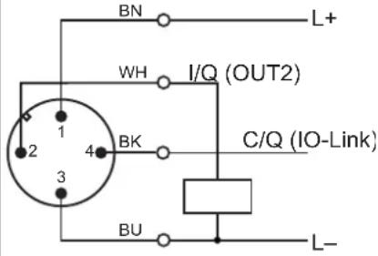 | 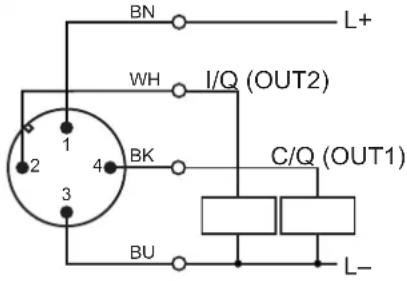 | |
| n-switching (NPN) | n-switching (NPN) | |
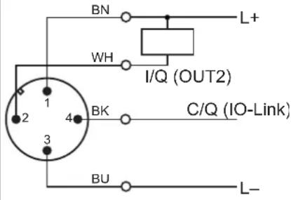 |  | |
Ex i
| Hazardous area | Safe area |
| JUMO Ex-i isolating switch amplifier | |
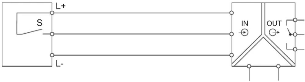 | for control device |
| e.g. AC/DC 24 to 230 V | |
Current limiting for capacitive loads
In the case of capacitive loads, the switching contact (S) must be protected with a resistor.
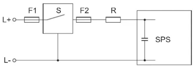
Protective circuit for inductive loads for capacitive loads
In the case of inductive loads, the switching contact (S) must be protected with a flyback diode.
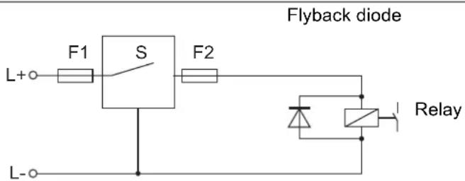
7 Installation
7.1 Functions
The device can be individually configured with an IO-Link master. As a matter of principle, the interface enables direct access to process and diagnosis data. Parameterization can be performed during the ongoing process. The new or modified configurations are only adopted once data has successfully been transmitted.

WARNING!
Risk of injury and material damage due to faulty system states
Injuries and material damage may occur due to system states that have been triggered in an uncontrolled manner.
The system must be in an error-free state.
The IODD file can be found under
https://ioddfinder.io-link.com/
by searching for the manufacturer, article number, device type, or device ID.
Alternatively, you can search on the website of the manufacturer https://en.jumo.de by entering the 4-digit product group number, and navigating to the product page with download area.
→ chapter 3.3 "Nameplate", Page 10
7.1.1 Structure of the operating menu
The menu structure is provided according to VDMA 24574-1 and supplemented with JUMO-specific menu items.
7.1.2 Preparation and structure of IO-Link communication
Requirements:
• The software (for example, IO-Link Device Tool) of the IO-Link master is installed on the computer.
Procedure:
-
Connect the device with the IO-Link master (see accessories) via the M12 connector.
-
Connect the IO-Link master for laboratory operation with the computer via the USB interface.
-
Import the IODD file.
→ chapter 7.1 "Functions", Page 28
- Connect the sensor.
→ chapter 5 "Mounting", Page 19
- Establish the connection via the software.
→ chapter 7.1 "Functions", Page 28
7.1.3 Teach-In function
The teach-in function is used for application-specific media detection. This can be used to teach in the present medium to the device.
External magnet and without additional software
Requirements:
- The system has been de-energized and secured against being switched on again.
Procedure:
- Hold the device in the medium.
- Position the magnet included in the accessories on the DMC code on the nameplate.
- Switch on the voltage supply.
Media detection starts and is signaled by a status display lighting up yellow. Once the parameters have been saved within the device, the status display lights up green for 1 s and then switches back to the configured signaling (default settings: yellow).
- The magnet and the medium can be removed.
It is also possible to perform the teach-in process in a laboratory; the values are saved when the voltage supply is removed and switched on again.
IO-Link communication
Requirements:
• The communication is established.
Procedure:
- Hold the device in the medium.
- Press the relevant teach button (SP1, SP2) in the Parameter menu item under Teach Single Value. Media detection starts. The parameters are automatically stored in the software when they have been determined. If required, the parameters can be modified and must then be transferred from the software to the device.
A wet test is not required if the parameters are known. The parameters per output (SP, FH, rP, FL) can be entered directly and transferred to other devices as a special configuration file (dry test).
7 Installation
7.1.4 Switching point and switching function
line
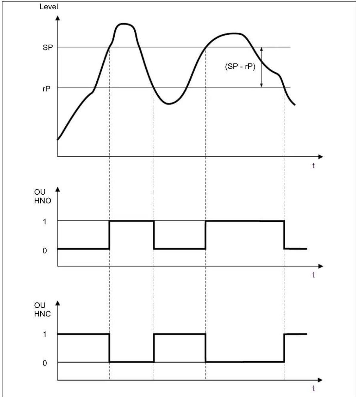
| Time | SP | SP - rP | OU HNO | OU HNC | |------|--------|---------|--------|--------| | t | Low | Low | 0 | 1 | | Mid | Peak | Peak | 1 | 0 | | End | Low | Low | 0 | 1 |The switching point (SP1, SP2) defines the limit value of the device related to the medium present (covering) to which the output (OU1, OU2) is to modify its switching status. The setting is an indication for the switching sensitivity of the device tip and can be adapted to the medium.
The release point (rP1, rP2) defines the limit value of the device related to the medium not present (uncovering) to which the output (OU1, OU2) is to modify its switching status. The release point must be lower than or equal to the switching point. When entering values for the release point greater than the switching point, a diagnostic message is generated. The difference between the switching point and the release point is defined as hysteresis (for example SP1 - rP1).
As long as the medium is between the two set points, the output is maintained to be constant, stable, and without any change of state.
The switching function of the output of the hysteresis can be parameterized as an NO contact or NC contact (HNO, HNC).
The HNC switching function is recommended for application as an overfill safeguard.
The HNO switching function is recommended for application as dry-run protection.
7 Installation
7.1.5 Window function, media detection, and media differentiation
line
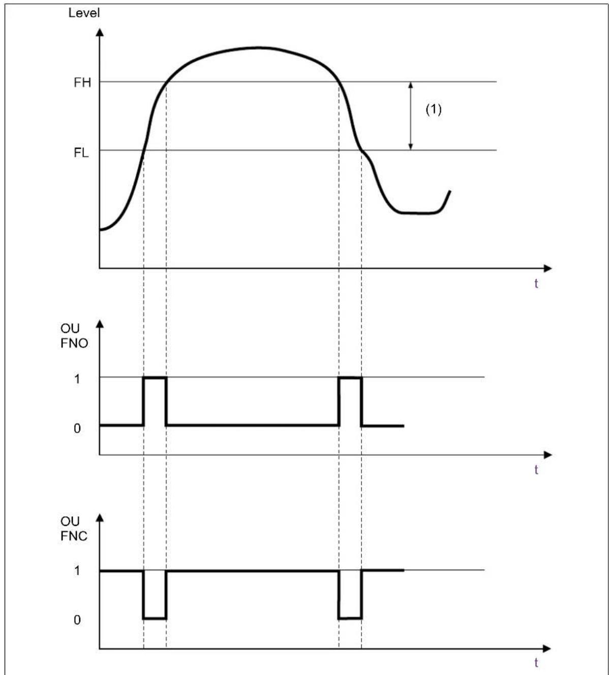
| Time Segment | Level | OU FNO | OU FNC | | ------------ | ----- | ------ | ------ | | t | FH | 0 | 1 | | t | FL | 0 | 0 | | t | (1) | 1 | 1 |(1) Level window
The window function (FH1 and FL1, FH2 and FL2) is used for media detection and media differentiation. Setpoint ranges are set using the relevant values. The Window High (FH) signals the upper limit value; the switching status of the output changes when this is reached. The Window Low (FH) signals the lower limit value; the switching status of the output changes when this is reached. The setting is therefore media-specific. If the median is between FL and FH, the output does not change. One output can be assigned per medium.
The switching function of the output of the window can be parametrized as an NO contact or NC contact (FNO, FNC).
7.1.6 Switching delay
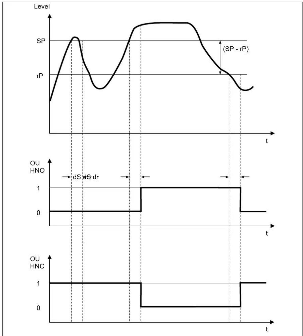
The time for the change of state of the switching output is set with the switch delays ds1 for channel 1 and ds2 for channel 2. The time can be entered in 0.1-second steps from 0 to 60 seconds.
The time for the change of state of the switching output is set with the reset delays dr1 and dr2. The time can be entered in 0.1-second steps from 0 to 60 seconds.
Can be used in practice for applications with fluctuating media (e.g. agitator).
7.1.7 Pulse-width modulation
With pulse width modulation, the duty cycle changes its values. This refers to the measured value from 0 to 100 % and adjusts itself automatically. Depending on the downstream evaluation unit, the period time can be set from 50 to 1000 ms. In this way, limit values can be stored independently in the evaluation unit.
7 Installation
7.1.8 Detection of pollution degree
Using detection of the pollution degree, the user can be notified of any deposits or adhesions that build up in order to initiate further maintenance measures in good time. The function signals whether pollution has been detected depending on the set trigger threshold (low, medium, high). In this case, "low" represents a low level of adhesions.
7.1.9 Auto-calibration
The capacitive level switch calibrates independently and continuously using the auto-calibration functionality.
While the auto-calibration routine is being carried out, the output signals remain in the state they were in before it was carried out. The routine takes 15 ms.
The operator must take this time for positioning the level switch into account during the design, especially in the case of overfill safeguards, to prevent the plant from overflowing or running dry, for example.
If the auto-calibration function is faulty, the sensor switches to the safe operating state and the status display turns red. The safe operating state is defined as the opposite signal to the original state at a switching point. Both outputs open when configuring two switching points (for example, anti-valent electrical circuit).
→ chapter 6 "Electrical connection", Page 22
An error status is transmitted when using digital transmission with IO-Link.
The default settings are shown in bold in the following tables.
Process data
| Parameter Default setting Description | ||
| Measured value – Display of the current measured value | ue in percent. | |
| Scaling 1 Display of scaling of measured value | ||
| State of switching output 1 (OU1) | Off | Display of current switching status of output 1 (OU1). |
| State of switching output 2 (OU2) | On | Display of current switching status of output 2 (OU2). |
| Device hardware fault False Displays whether there is a device | hardware fault. | |
| Parameter error False Displays whether there is a parameter error. | ||
| Auto-calibration error False Displays whether an error has occurred during auto-calibration. | ||
| Pollution degree | False | Displays whether pollutants are detected. |
Identification
| Parameter Default setting Description | ||
| Application-specific TAG | - | For identification of specific application, function and operating location with up to 32 characters (alpha-numeric and special characters). |
| Function TAG | - | |
| Location TAG | - | |
Monitoring
| Parameter Default setting Description | ||
| Measured value - | Display of the current measured value in %. | |
| State of switching output 1 (OU1) | Off | Display of current switching status of output 1 (OU1). |
| State of switching output 2 (OU2) | On | Display of current switching status of output 2 (OU2). |
| Device hardware faultFalse Displays whether there is a device | hardware fault. | |
| Parameter errorFalse Displays whether there is a parameter error. | ||
| Auto-calibration errorFalse Displays whether an error has occurred during auto-calibration. | ||
| Pollution degree | No biofilm detected | Displays whether pollutants have been detected. |
| Pollution value | - | Display of current pollution value. |
Parameter
| Parameter Default setting Description | ||
| Configuration | Standard, user | Sets the scope of configuration options. |
| Reset configuration settings – Button for resetting the configuration | that has been made. | |
| Switching channel 1, output signal | O-Link, PNP, NPN, push-pull, push-pull PWM | Setting according to variant ordered, see order code. |
| Switching channel 1, limit value/ window HIGH (SP1/FH1) | Input range:0 to 100.0 % (25) | Sets the limit value that must at least be available to change the switching status.Input range value > switching chan-nel value 1 release point/window Low (rP1/FL1) |
| Switching channel 1, switching be-havior (OU1) | High-active (MAX, HNC, FNC), low-active (MIN, HNO, FNO) | Setting of the switching behavior as high- or low-active. |
| Switching channel 1, mode Single | point, window (FH, FL), two point | - |
| Switching channel 1, hysteresis Input range:0 to 100.0 % (0) | - | |
| Switching channel 1, release point/ window low (rP1/FL1) | Input range:0 to 100.0 % (-) | Input range value < switching chan-nel value 1 limit value / window HIGH (SP1/FH1) |
| Switching channel 1, switching de-lay time (ds1) | Input range:0 . 3 to 6 0 s (0.5) | Time display in 0.1-second steps. |
| Switching channel 1, release delay time (dr1) | Input range:0,3 bis 60 s (1.0) | Time display in 0.1-second steps. |
| Switching channel 1 pulse width modulation (PWM) – period time | 50 to 1000 ms (-) | Period duration in relation to mea-sured value. |
| Switching channel 2, output signal | PNP, NPN, push-pull | Setting according to variant ordered, see order code. |
| Switching channel 2, limit value/ window HIGH (SP2/FH2) | Input range:0 to 100.0 % (25) | Input range value > switching chan-nel value 2 release point/window Low (rP2/FL2) |
| Switching channel 2, switching be-havior (OU2) | High-active (MAX, HNC, FNC), low-active (MIN, HNO, FNO) | - |
| Switching channel 2, mode Single | point, window (FH, FL), two point | - |
| Switching channel 2, hysteresis Input range:0 to 100.0 % (0) | - | |
| Switching channel 2, release point/ window Low (rP2/FL2) | Input range:0 to 100.0 % (-) | Input range value < switching chan-nel value 2 limit value/window HIGH (SP2/FH2) |
| Switching channel 2, switching de-lay time (ds2) | Input range:0 . 3 to 6 0 s (0.5) | Time display in 0.1-second steps. |
| Switching channel 2, release delay time (dr2) | Input range:0,3 bis 60 s (1.0) | Time display in 0.1-second steps. |
| Switching channel 2 pulse width modulation (PWM) – period time | 50 to 1000 ms (-) | Period duration in relation to mea-sured value. |
| Teach function selection Switching | channel 1,switching channel 2 | Selection of output channel on which the teach function is to have an ef-fect. |
| Parameter | Default setting | Description |
| System command Teach SP1 Teach | h button in the software to teach | achin switching point 1 of the selected switching channel. |
| Teach SP2 Teach button in | the software to teachin switching point 1 of the selected switching channel (for window or two point mode). | |
| Event setting, auto-calibration error | False Setting to transmit an | event in the case of an error during auto-calibration. |
| Event setting, pollution degree | False | Setting to transmit an event in the event the pollution degree is exceeded. |
| Status display according to | IO-Link, NE 107, user-defined | - |
| Brightness of the status display Eco-mode, medium, high, maximum | - | |
| Pollution degree Selection list: | low, medium, high (-) | - |
| Filter time constant Input range: | 0 to 100 s (-) | - |
| Temperature unit °C, °F - | ||
| Load default settings (rES) – Reset | to default settings. | |
Diagnostics
| Parameter | Default setting | Input option |
| Device status | - Shows information about the device status. | |
| Error counter | - Shows information on the number of registered errors. | |
| System command back-to-box | - | IO-Link-specific button for resetting the default settings. |
| System command locator start | - | IO-Link-specific button to have the installed device flash in the plant. |
| System command locator stop | - | IO-Link-specific button to have the device installed in the plant no longer flash. |
| Current diagnosis information | - Display of current diagnostic message. | |
| Last diagnosis information | - Display of the last diagnostic message. | |
| Simulation mode | On, Off | Activate or deactivate simulation mode. |
| Measured value simulation Input range: 0 to 100 % (-) | Input of a simulated measured value. | |
| Service commands reset all service parameters | - Button that resets all service parameters listed in the sub-menu. | |
| Service command reset operating hours | - Button that resets the operating hours counter. | |
8 Parameterization
| Parameter Default setting Input option | ||
| Service command reset drag indicator min. temperature | – Button that resets the drag | indicatorfor the minimum temperature. |
| Service command reset drag indicator max. temperature | – Button that resets the drag | indicatorfor the maximum temperature. |
| Electronic components temperature | --.- Display of the current elec | ctroniccomponents temperature. |
| Operating hours counter 0 h Display | ay of the current operating | hours. |
| MIN. electronic components temperature | --.- Display of the minimum electroniccomponents temperature. | |
| MAX. electronic components temperature | --.- Display of the maximum electroniccomponents temperature. | |
| Error Possible cause Remedy | ||
| Installation is not possible. | Process connection was dimensioned incorrectly. | Contact manufacturer. |
| Modify the tank or container connection. | ||
| The process connection on the tank is damaged. | Rework the thread. | |
| Replace the process connection. | ||
| The process connection on the device is damaged. | Return the device.⇒ chapter 11.3 "Returns", Page 44 | |
| The switching function of the device ist is faulty. | The device was operated outside the admissible limits. | Test the operating conditions of the device and compare with the technical data.⇒ chapter 4 "Technical data", Page 12 |
| The electrical connection is faulty. | Test the terminal assignment and startup.⇒ chapter 7 "Installation", Page 28 | |
| There are deposits or contamination on the device. | Clean the device.⇒ chapter 10 "Maintenance and cleaning", Page 43 | |
| The switching output is faulty. | Return the device.⇒ chapter 11.3 "Returns", Page 44 | |
| The output signal of the device is faulty. | The electrical connection is faulty. | Test terminal assignment and startup taking the entire measuring circuit into consideration.⇒ chapter 7 "Installation", Page 28 |
| There are deposits or contamination on the device. | Clean the device.⇒ chapter 10 "Maintenance and cleaning", Page 43 | |
| The electronic components are faulty.Output signal according to NAMUR NE 107/VDE 2650 | Return the device.⇒ chapter 11.3 "Returns", Page 44 | |
| An electrical fault has occurred due to overvoltage (e.g. thunderbolt). | ||
| The status display does not light up. | There is no voltage supply. Test | the connectors, cables and voltage supply. |
| The electronic components are faulty. | Return the device.⇒ chapter 11.3 "Returns", Page 44 | |
| The status display flashes red. | There has been an overload or a short circuit in the electrical circuit. | Remedy the short circuit or reduce load current according to data sheet.⇒ chapter 4 "Technical data", Page 12 |
| The ambient temperature does not correspond to the admissible temperature range. | Operate the device within the stipulated temperature range.⇒ chapter 4 "Technical data", Page 12 | |
| The status display lights up red. | An internal device error has occurred. | Replace the device.⇒ chapter 11 "Shutdown", Page 44 |
9 Troubleshooting
| Error Possible cause Remedy | ||
| The device does not re-spond. | The voltage supply does not match the specification on the nameplate. | Apply the admissible voltage.⇒ chapter 3.3 "Nameplate", Page 10 |
| Polarity of the voltage supply is wrong. | Reverse the polarity of the voltage supply. | |
| Mating connectors or the cable have no electrical contact for signal transmission. | Test and adapt the corresponding contact. | |
| No communication possible (for versions with IO-Link). | The communication line is not connected or is connected incorrectly. | Test the terminal assignment and the electrical connection.⇒ chapter 7 "Installation", Page 28 |
| Transmission of measured values is not possible (for versions with IO-Link). | An internal device error has occurred. | Remedy the error according to the diagnosis result shown.⇒ chapter 9.1 "Diagnostic events", Page 41 |
9.1 Diagnostic events
Malfunctions that the device detects using self-monitoring do not fulfill any safety function and are output as diagnostic messages with IO-Link. The switching outputs modify their state to open. The measurements are interrupted.
Warnings that the device detects using self-monitoring do not fulfill any safety function and are output as diagnostic messages with IO-Link. The switching outputs remain in their state which is present on the application side at this time. The measurements are continued and updated.
The device provides information about the status information according to NAMUR NE 107 and VDI/VDE 2650.
| Symbol Diagnostics Designation | ||
| F Failure There is a device error. The measured value is no longer valid. | ||
| M Maintenance required | Maintenance is required. The measured value is still valid. | |
| C Functional check The device is in service mode (e.g. during a simulation). | ||
| S Outside the specification | The device is operated:Outside its technical specifications (e.g. during the launch phase or cleaning)Outside the parameterization made by the user (e.g. level outside the parameterized range) | |
| Pictogram | Status message |
| Failure | |
| Outside the specification | |
| Functional check | |
| Maintenance required |
The diagnosis result can be detected using the following table. If multiple diagnostic events occur at the same time, only the diagnostic message with the higher priority is displayed.
| Diagnostic event | ||
| Status signal | Event number | |
| ↓ | ↓ | |
| Example | C | 101 |
| Code | Behavior of status display | Diagnostics Possible cause Remedy | ||
| F000 | Lights up red Other | errors Not precisely specified | specified | Test the installation situation and electrical connection. Return the device if error is present.⇒ chapter 11.3 "Returns", Page 44 |
| F001 | Lights up red General software error | A software error has occurred. | Restart the device. | |
| F002 | Lights up red Error during calibration | An error within the device has occurred. | Return the device.⇒ chapter 11.3 "Returns", Page 44 | |
| F003 | Lights up red Error in the device settings | Error has occurred during the default calibration. | Restart the configuration. | |
| The EEPROM is faulty. | ||||
| The configuration data contain a checksum error. | ||||
| F004 | Lights up red Teach-in procedure is faulty | An error has occurred during the teach-in procedure. | Disconnect the voltage supply, switch it on again and retrigger the teach-in procedure. Return the device if error is present.⇒ chapter 11.3 "Returns", Page 44 | |
| C101 | Flashing red Simulation active The simulation is currently being performed. | Location is currently being performed. | Exit the simulation. | |
| S201 | Flashing red Outside the admissible temperature range | The temperature range is not admissible. | Test the ambient temperature. Insulate if necessary in the event of excessively low temperatures, cool if necessary in the event of excessively high temperatures.⇒ chapter 4 "Technical data", Page 12 | |
| S202 | Flashing red Switching output overloaded | An overload or short circuit has occurred at the switching output. | Test the electrical connection, increase load resistance at the switching output if necessary.⇒ chapter 7 "Installation", Page 28 | |
| S203 | Flashing red Outside the admissible voltage supply range | Voltage supply has been exceeded. | Test the electrical connection for correct installation.⇒ chapter 6 "Electrical connection", Page 22 | |
| M301 | Lights up blue Pollution degree detected | The coating thickness is inadmissible. | Clean the device.⇒ chapter 10 "Maintenance and cleaning", Page 43 |
The device is maintenance-free.
When pressure testing the container or the pipe, adhere to the admissible limit values.
⇒ chapter 4 "Technical data", Page 12
Requirements:
- The system has been de-energized and secured against being switched on again.
Procedure:
Cleaning of the part in contact with the medium may only be carried out when it is installed (e.g. CIP – Cleaning in Place or SIP – Sterilization in Place).
Observe the technical data with regard to temperature and pressure specifications.
→ chapter 4 "Technical data", Page 12
NOTICE!
Damage to the device resulting from improper cleaning.
▶ Damp cloths or compressed air (< 6 bar) are admissible for cleaning.
▶ Do not use any sharp or hard objects (e. g. wire brushes) for cleaning.
▶ Use a suitable cleaning agent that does not affect the materials (chemically and mechanically).
▶ Avoid humidity in the electrical connection.
11 Shutdown
11.1 Dismounting
Requirements:
- The plant has been de-pressurized, de-energized and secured against being switched on again.
• The device is media-free.
Aids Open-end wrench or ring spanner
NOTICE!
Damage to the device tip due to improper handling.
The device tip may be damaged during dismounting.
▶ Check the device tip for notches or grooves.
11.2 Decontamination
Requirements:
• The device is disassembled.
- Suitable protective equipment has been set up.
- A suitable cleaning agent is available.
- A cleaning area for flushing and neutralizing all parts that come into contact with the medium is prepared.
Procedure:
- CAUTION! Only use cleaning agents that are compatible with the materials used to make the device. Thoroughly flush and neutralize all parts that come into contact with the medium using a suitable cleaning agent.
- For return to the manufacturer: chapter 11.3 "Returns", Page 44.
- For disposal: chapter 11.4 "Disposal", Page 44.
11.3 Returns
Procedure:
- The supplementary sheet for product returns must first be completed correctly and signed. Then enclose it with the shipping documents and attach it to the packaging, ideally on the outside.
- Use the original packaging or a suitably secure container for sending the device.
11.4 Disposal

- Do not dispose of the device or replaced parts in the trash after use.
- Delete programs and data stored on the device.
- Remove batteries, if any, if this can be done without damaging the device.
- Dispose of the device and the packaging material in a responsible and environmentally friendly manner.
- Observe the country-specific laws and regulations for waste treatment and disposal.
In accordance with Directive 2012/19/EU on Waste from Electrical and Electronic Equipment, manufacturers are obliged to offer the option of returning waste equipment. Request the return from the manufacturer.
When using a device with UL application, the user has to ensure that the accessories he uses are also approved for a UL application (e.g. cables with UL approval AVLV2/8 suitable for external connection and/or cables with UL approval CYJV/7 or CYJV/8 or PVVA/7 or PVVA2/8, each approved for ambient temperatures > 80 °C).
| Designation Part no. | |
| Connection line M8/voltage supply, length 2 m, IO-Link master, 4 channel, with UL approval | 00767913 |
| Connection line M8/Ethernet, length 2 m, IO-Link master, 4 channel, with UL approval | 00767923 |
| Connection line M12/voltage supply, length 2 m, IO-Link master, 8 channel, with UL approval | 00767914 |
| Connection line M12/Ethernet, length 2 m, IO-Link master, 8 channel, with UL approval | 00767927 |
| USB IO-Link master, 1-channel 00694070 | |
| IO-Link master, 4 channel, with UL approval 00759867 | |
| IO-Link master, 8 channel, with UL approval 00759875 | |
| Magnetic pen for teach function 00736330 | |
| Welding socket G 1/2" for process connection 387 00378264 | |
| Adapter G 1/2" VARIVENT Type N DN 50/40 | 30054461 |
| T-piece with PEKA connection DN 100 | 00643582 |
| T-piece with PEKA connection DN 80 | 00643581 |
| T-piece with PEKA connection DN 65 | 00643580 |
| T-piece with PEKA connection DN 50 | 00643579 |
| T-piece with PEKA connection DN 40 | 00643576 |
| T-piece with PEKA connection DN 32 | 00643574 |
| T-piece with PEKA connection DN 25 | 00643555 |
| T-piece with screw connection G 1/2" DN 100 | 00772334 |
| T-piece with screw connection G 1/2" DN 80 | 00772333 |
| T-piece with screw connection G 1/2" DN 65 | 00772332 |
| T-piece with screw connection G 1/2" DN 50 | 00772331 |
| T-piece with screw connection G 1/2" DN 40 | 00772330 |
| T-piece with screw connection G 1/2" DN 32 | 00772321 |
| T-piece with screw connection G 1/2" DN 25 | 00772316 |
| Configuration cable for Ex devices | 30048990 |
| Connection line M12, M12, black, PUR, length 2 m (straight coupling/straight connector; 5 pole; A-coded) | 00777804 |
| Cable PUR, 4 × 0.34, black, length 2 m, with UL approval | 00776248 |
| Cable PUR, 4 × 0.34, black, length 5 m, with UL approval | 00776250 |
| Cable PUR, 4 × 0.34, black, length 10 m, with UL approval | 00776252 |
| Line socket, 4-pole, M12 × 1, straight, length 2 m | 00404585 |
| Line socket, 4-pole, M12 × 1, angled, length 2 m | 00409334 |
| Sealing ring A24 × 2 - Vf for process connection 133 | 00704485 |
| Sealing ring A26 × 2 - Vf for process connection 105 | 30049315 |
| Service deployment | 00427970 |
| Preconfiguration (Service) | 00427968 |
JUMO
JUMO GmbH & Co. KG JUMO UKL TD JUMO Process Control, Inc.
Street address:
36039 Fulda, Germany
Delivery address:
Mackenrodtstraße 14
36039 Fulda, Germany
Postal address:
36035 Fulda, Germany
Phone: +49 661 6003-0
Fax: +49 661 6003-607
Email: mail@jumo.net
Internet: www.jumo.net
JUMO House
Temple Bank, Riverway
Harlow, Essex, CM20 2DY, UK
Phone: +44 1279 63 55 33
Fax: +44 1279 62 50 29
Email: sales@jumo.co.uk
Internet: www.jumo.co.uk
6724 Joy Road
East Syracuse, NY 13057, USA
Phone: +1 315 437 5866
Fax: +1 315 437 5860
Email: info.us@jumo.net
Internet: www.jumousa.com

JUMO ZELOS
natural_image
Product comparison of JUMO engine components, showing a cylindrical tool and three metallic cylindrical plugs with blue and green connectors (no text or symbols visible)qr-408401-fr.jumo.info
7 Installation....28
7.1 Fonctions 28
natural_image
Three technical illustrations of a mechanical component under different conditions: before contact, mid-cavity, and after contact (no text or symbols present)Conditions requises :
natural_image
Cross-sectional illustration of a cylindrical container with liquid and a green cap, no text or symbols present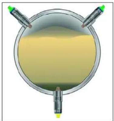
natural_image
Top-down view of a circular container with yellow liquid and two green test tubes, no text or symbols visible.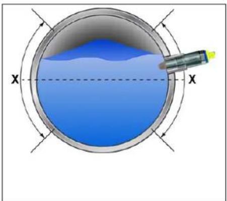
natural_image
Cross-sectional diagram of a circular container with blue liquid and a probe inserted, labeled X (no text or symbols beyond labels)Fig. 5-2 Pas d'autovidange possible
https://ioddfinder.io-link.com/
Conditions requises :
Conditions requises :
Communication IO-Link
Conditions requises :
line
| Time | Niveau | SP | rP | OU HNO | OU HNC | |------|--------|----|----|--------|--------| | t | Low | Low| Low| 0 | 1 | | Mid | Peak | High | Low| 1 | 0 | | End | Low | Low| Low| 0 | 1 |line
| t | Niveau | OU HNO | OU HNC | |-------|--------|--------|--------| | 0 | Low | 0 | 1 | | 1 | High | 1 | 0 | | 2 | Low | 0 | 1 | | 3 | High | 1 | 0 | | 4 | Low | 0 | 1 | | 5 | High | 1 | 0 | | 6 | Low | 0 | 1 | | 7 | High | 1 | 0 | | 8 | Low | 0 | 1 | | 9 | High | 1 | 0 | | 10 | Low | 0 | 1 | | 11 | High | 1 | 0 | | 12 | Low | 0 | 1 | | 13 | High | 1 | 0 | | 14 | Low | 0 | 1 | | 15 | High | 1 | 0 | | 16 | Low | 0 | 1 | | 17 | High | 1 | 0 | | 18 | Low | 0 | 1 | | 19 | High | 1 | 0 | | 20 | Low | 0 | 1 | | 21 | High | 1 | 0 | | 22 | Low | 0 | 1 | | 23 | High | 1 | 0 | | 24 | Low | 0 | 1 | | 25 | High | 1 | 0 | | 26 | Low | 0 | 1 | | 27 | High | 1 | 0 | | 28 | Low | 0 | 1 | | 29 | High | 1 | 0 | | 30 | Low | 0 | 1 | | 31 | High | 1 | 0 | | 32 | Low | 0 | 1 | | 33 | High | 1 | 0 | | 34 | Low | 0 | 1 | | 35 | High | 1 | 0 | | 36 | Low | 0 | 1 | | 37 | High | 1 | 0 | | 38 | Low | 0 | 1 | | 39 | High | 1 | 0 | | 40 | Low | 0 | 1 | | 41 | High | 1 | 0 | | 42 | Low | 0 | 1 | | 43 | High | 1 | 0 | | 44 | Low | 0 | 1 | | 45 | High | 1 | 0 | | 46 | Low | 0 | 1 | | 47 | High | 1 | 0 | | 48 | Low | 0 | 1 | | 49 | High | 1 | 0 | | 50 | Low | 0 | 1 | | Note: The data is extracted from the image. The labels for the plots are 'SP' and 'rP', but they are not explicitly provided in the code. There is no additional data series in this view. The values for 'dS' and 'dS dr' are not explicitly labeled in the chart.Conditions requises :
Conditions requises :
Conditions requises :
natural_image
Product comparison of JUMO engine components, showing a cylindrical tool and three metallic cylindrical plugs with blue and green connectors (no text or symbols visible)Manual de servicio
qr-408401-es.jumo.info
natural_image
Three technical illustrations of a mechanical component under different conditions: before, after, and after water displacement (no text or symbols present)natural_image
Cross-sectional illustration of a cylindrical container with liquid and a green cap, no text or symbols present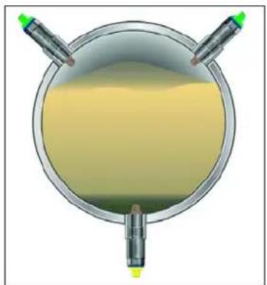
natural_image
Top-down view of a circular container filled with yellow liquid, with two side handles and green indicator lights (no text or symbols)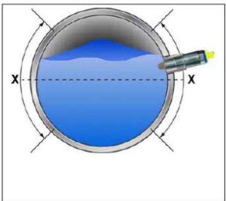
natural_image
Cross-sectional diagram of a circular container with blue liquid and a probe inserted, labeled X (no text or symbols beyond labels)Dispositivo Conector M12
https://ioddfinder.io-link.com/
line
| Time | SP | rP | |------|--------|--------| | t | Low | Low | | 0 | High | Low | | 1 | High | Low | | 2 | Medium | Low | | 3 | Low | Low | | 4 | High | Low | | 5 | High | Low | | 6 | Medium | Low | | 7 | Low | Low | | 8 | High | Low | | 9 | High | Low | | 10 | Medium | Low | | 11 | Low | Low | | 12 | High | Low | | 13 | High | Low | | 14 | Medium | Low | | 15 | Low | Low | | 16 | High | Low | | 17 | High | Low | | 18 | Medium | Low | | 19 | Low | Low | | 20 | High | Low | | 21 | High | Low | | 22 | Medium | Low | | 23 | Low | Low | | 24 | High | Low | | 25 | High | Low | | 26 | Medium | Low | | 27 | Low | Low | | 28 | High | Low | | 29 | High | Low | | 30 | Medium | Low | | 31 | Low | Low | | 32 | High | Low | | 33 | High | Low | | 34 | Medium | Low | | 35 | Low | Low | | 36 | High | Low | | 37 | High | Low | | 38 | Medium | Low | | 39 | Low | Low | | 40 | High | Low | | 41 | High | Low | | 42 | Medium | Low | | 43 | Low | Low | | 44 | High | Low | | 45 | High | Low | | 46 | Medium | Low | | 47 | Low | Low | | 48 | High | Low | | 49 | High | Low | | 50 | Medium | Low | | 51 | Low | Low | | 52 | High | Low | | 53 | High | Low | | 54 | Medium | Low | | 55 | Low | Low | | 56 | High | Low | | 57 | High | Low | | 58 | Medium | Low | | 59 | Low | Low | | 60 | High | Low | | 61 | High | Low | | 62 | Medium | Low | | 63 | Low | Low | | 64 | High | Low | | 65 | High | Low | | 66 | Medium | Low | | 67 | Low | Low | | 68 | High | Low | | 69 | High | Low | | 70 | Medium | Low | | 71 | Low | Low | | 72 | High | Low | | 73 | High | Low | | 74 | Medium | Low | | 75 | Low | Low | | 76 | High | Low | | 77 | High | Low | | 78 | Medium | Low | | 79 | Low | Low | | 80 | High | Low | | 81 | High | Low | | 82 | Medium | Low | | 83 | Low | Low | | 84 | High | Low | | 85 | High | Low | | 86 | Medium | Low | | 87 | Low | Low | | 88 | High | Low | | 89 | High | Low | | 90 | Medium | Low | | 91 | Low | Low | | 92 | High | Low | | 93 | High | Low | | 94 | Medium | Low | | 95 | Low | Low | | 96 | High | Low | | 97 | High | Low | | 98 | Medium | Low | | 99 | Low | Low | | 100 | High | Low | | 101 | High | Low | | 102 | Medium | Low | | 103 | Low | Low | | 104 | High | Low | | 105 | High | Low | | 106 | Medium | Low | | 107 | Low | Low | | 108 | High | Low | | 109 | High | Low | | 110 | Medium | Low | | 111 | Low | Low | | 112 | High | Low | | 113 | High | Low | | 114 | Medium | Low | | 115 | Low | Low | | 116 | High | Low | | 117 | High | Low | | 118 | Medium | Low | | 119 | Low | Low | | 120 120.5.5.5.5.5.5.5.5.5.5.5.5.5.5.5.5.5.5.5.5.5.5.5.5.5.5.5.5.5.5.5.5.5.5.5.5.5.5.5.5.5.5.5.5.5.5.5.5.5.5.0.0.0.0.0.0.0.0.0.0.0.0.0.0.0.0.0.0.0.0.0.0.0.0.0.0.0.0.0.0.0.0.0.0.0.0.0.0.0.0.0.0.0.0.0.0.0.0.0.
- JUMO ZELOS
- Installation....28
- Series of capacitive level switches
- About this documentation ....5
- Safety 6
- Description....8
- Technical data ....12
- Mounting ....19
- Electrical connection ..... 22
- Table of contents
- Parameterization....35
- Troubleshooting ....39
- Maintenance and cleaning ....43
- Shutdown....44
- Accessories....45
- Purpose
- Target group
- Definition of terms
- Symbols
- WARNING!
- NOTICE!
- REFERENCE!
- Safety
- Intended use
- Qualification of personnel
- Risk assessment
- Hot surface
- Hazardous materials
- Mechanical load
- Hybrid mixtures
- Transport and storage damage
- Description
- Structure
- Function
- Nameplate
- Scope of delivery
- Electrical data
- Inputs
- Outputs
- Interface
- Display
- Environmental influences
- Technical data
- Mechanical features
- Dimensions
- Device
- Process connections
- Cable
- Risk of poisoning and suffocation due to the leakage of corrosive and toxic media
- Requirements:
- Mounting
- Risk of injury and material damage due to faulty connection
- Risk of injury and material damage due to faulty system states
- Connection elements
- Terminal assignment
- M12 plug connector
- Electrical connection
- Connection examples
- Current limiting for capacitive loads
- Protective circuit for inductive loads for capacitive loads
- Installation
- Functions
- Structure of the operating menu
- Preparation and structure of IO-Link communication
- Teach-In function
- External magnet and without additional software
- IO-Link communication
- Switching point and switching function
- Window function, media detection, and media differentiation
- Switching delay
- Pulse-width modulation
- Detection of pollution degree
- Auto-calibration
- Parameterization
- Troubleshooting
- Diagnostic events
- Damage to the device resulting from improper cleaning.
- Shutdown
- Dismounting
- Decontamination
- Procedure:
- Returns
- Disposal
- JUMO
- JUMO GmbH & Co. KG JUMO UKL TD JUMO Process Control, Inc.
- Conditions requises :
- Communication IO-Link
Brand : Jumo
Model : 408401
Category : Measuring equipment