di eco - Temperature Controller Jumo - Free user manual and instructions
Find the device manual for free di eco Jumo in PDF.

User questions about di eco Jumo
0 question about this device. Answer the ones you know or ask your own.
Ask a new question about this device
Download the instructions for your Temperature Controller in PDF format for free! Find your manual di eco - Jumo and take your electronic device back in hand. On this page are published all the documents necessary for the use of your device. di eco by Jumo.
USER MANUAL di eco Jumo
Operating Instructions
natural_image
Digital laboratory setup with a digital display showing 0.00, connected to a black connector (no visible text or symbols)6 A l a r m m e l d u n g e n
36039 Fulda, Germany
Lieferadresse:
Mackenrodtstraße 14
36039 Fulda, Germany
Postadresse:
36035 Fulda, Germany
Telefon: +49 661 6003-0
Telefax: +49 661 6003-500
E-Mail: mail@jumo.net
Internet: www.jumo.net
JUMO
8712 Stäfa, Switzerland
Telefon: +41 44 928 24 44
Telefax: +41 44 928 24 48
E-Mail: info@jumo.ch
Operating Instructions
10.04
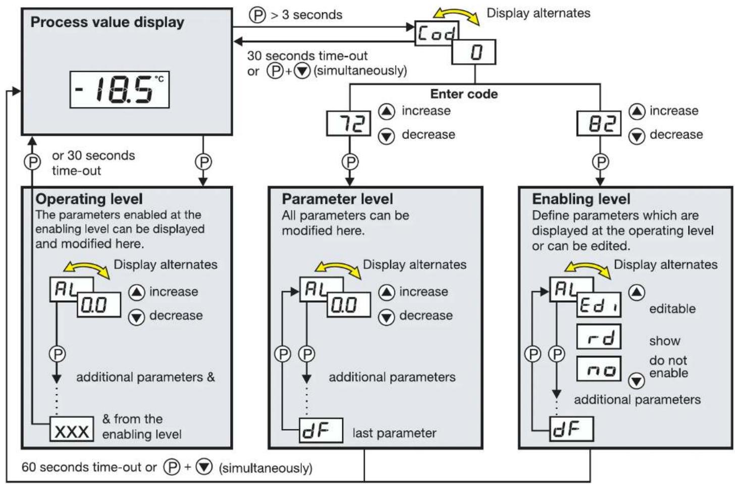
Overview of operation
flowchart
graph TD
    A["Process value display -18.5°C"] --> B["Operating level"]
    B --> C["Parameter level"]
    C --> D["Enabling level"]
    A -->|P > 3 seconds| E["Code 0"]
    E --> F["Enter code"]
    F --> G["72"]
    G --> H["82"]
    H --> I["90"]
    I --> J["90"]
    J --> K["90"]
    K --> L["90"]
    L --> M["90"]
    M --> N["90"]
    N --> O["90"]
    O --> P["90"]
    P --> Q["90"]
    Q --> R["90"]
    R --> S["90"]
    S --> T["90"]
    T --> U["90"]
    U --> V["90"]
    V --> W["90"]
    W --> X["90"]
    X --> Y["90"]
    Y --> Z["90"]
    Z --> AA["90"]
    AA --> AB["90"]
    AB --> AC["90"]
    AC --> AD["90"]
    AD --> AE["90"]
    AE --> AF["90"]
    AF --> AG["90"]
    AG --> AH["90"]
    AH --> AI["90"]
    AI --> AJ["90"]
    AJ --> AK["90"]
    AK --> AL["90"]
    AL --> AM["90"]
    AM --> AN["90"]
    AN --> AO["90"]
    AO --> AP["90"]
    AP --> AQ["90"]
    AQ --> AR["90"]
    AR --> AS["90"]
    AS --> AT["90"]
    AT --> AU["90"]
    AU --> AV["90"]
    AV --> AW["90"]
    AW --> AX["90"]
    AX --> AY["90"]
    AY --> AZ["90"]
    AZ --> BA["90"]
    BA --> BB["90"]
    BB --> BC["90"]
    BC --> BD["90"]
    BD --> BE["90"]
    BE --> BF["90"]
    BF --> BG["90"]
    BG --> BH["90"]
    BH --> BI["90"]
    BI --> BJ["90"]
    BJ --> BK["90"]
    BK --> BL["90"]
    BL --> BM["90"]
    BM --> BN["90"]
    BN --> BO["90"]
    BO --> BP["90"]
    BP --> BQ["90"]
    BQ --> BR["90"]
    BR --> BS["90"]
    BS --> BT["90"]
    BT --> BU["90"]
    BU --> BV["90"]
    BV --> BW["90"]
    BW --> BX["90"]
    BX --> BY["90"]
    BY --> BZ["90"]
Contents
1 Instrument identification ....4
2 Mounting 6
3 Electrical connection 7
3.1 Installation notes 7
3.2 Connection diagram 8
4 Commissioning the instrument 9
4.1 Displays and controls 9
4.2 Operating level 10
4.3 Setting the instrument functions (parameter level) ..... 11
4.4 Allocating user rights (enabling level) ..... 16
5 Technical data 17
5.1 Setup program ....20
6 Alarm messages 21
1 Instrument identification
The nameplate is glued to the bottom of the instrument. The supply voltage that is connected must correspond to the voltage specified on the nameplate.

All necessary settings are described in these Operating Instructions. If any difficulties should still arise during start-up, you are asked not to carry out any unauthorized manipulations on the unit. You could endanger your rights under the instrument warranty! Please contact the nearest subsidiary or the head office.
Please read these operating instructions carefully before commissioning the instrument. Keep the manual in a place that is accessible to all users at all times. Please assist us to improve these operating instructions, where necessary.
text_image
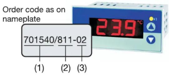
Order code as on nameplate 701540/811-02 (1) (2) (3) 23.9 °CDelivery package
1 seal
1 mounting frame
1 Operating Instructions 70.1540.0
701540/ JUMO di eco
(1) Basic version
(2) Basic type extension
Version
8 factory-set, configurable within the
measurement input group
9 configured to customer specification
Measurement input group ^1
1 Pt100 in 2-wire circuit
Pt 1000 in 2-wire circuit
KTY2X-6
2 Fe-Con J
Fe-Con L
NiCr-Ni K
30 - 20 mA
4 - 20 mA
40 - 10 V
1 1 changeover 10A/250V
(3) Supply
02 230V AC +10/-15% 48 - 63Hz
05 115V AC +10/-15% 48 - 63Hz
31 12 - 24V DC +15/-15% /
24V AC +15/-15% 48 - 63Hz
(1) (2) (3)
Order code /
Order example

701540 / 811 - 02
factory-set
1.) It is not possible to switch from one measurement input group to another.
2 Mounting
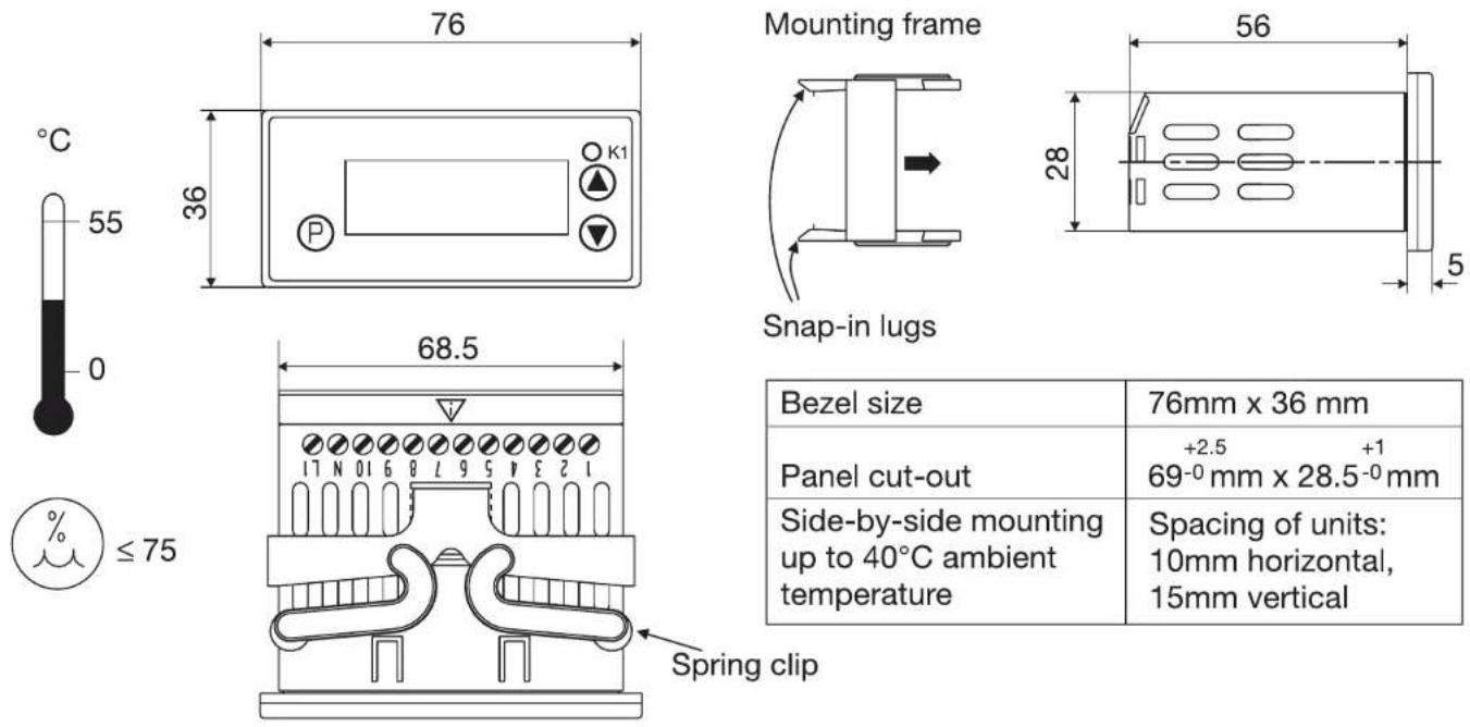
| Bezel size | 76mm x 36 mm |
| Panel cut-out | +2.5 +169-0mm x 28.5-0mm |
| Side-by-side mounting up to 40°C ambient temperature | Spacing of units:10mm horizontal,15mm vertical |
*Pull off mounting frame from instrument.
* Insert the instrument from the front into the panel cut-out and make sure that the bezel seal is seated correctly.
*From the back, push mounting frame onto the housing until the spring clips are under tension and the snap-in lugs have engaged at top and bottom.
3 Electrical connection
3.1 Installation notes
☐ The choice of cable, the installation, the fusing and the electrical connection of the instrument must conform to the requirements of VDE 0100 “Regulations on the Installation of Power Circuits with nominal voltages below 1000 V” or the appropriate local regulations.
☐ The electrical connection must only be carried out by qualified personnel.
☐ The electromagnetic compatibility conforms to the standards and regulations listed under Technical data.
☐ The instrument is not suitable for installation in areas with an explosion hazard and must be built into a housing that provides protection against fire/electrical hazards.
☐ The load circuit must be fused for the maximum relay current in order to prevent welding of the output relay contacts in the event of a short circuit.
☐ Do not connect any additional loads to the supply terminals of the instrument.
☐ The external fuse of the supply should not be rated below 1A, depending on the conductor cross-section. If contact with live components is possible while working on the instrument, it must be disconnected on all poles from the supply (e.g. via a separate mains supply switch).
| □ Supply Measurement input and supply | ||
| 230V AC and 115V AC short-circuit-proof electrically isolated from each other | ||
| 12 — 24V DC and 24V AC | not short-circuit-proof | not electrically isolated from each other |
3.2 Connection diagram

The electrical connection must only be carried out by qualified personnel!
Relay K1
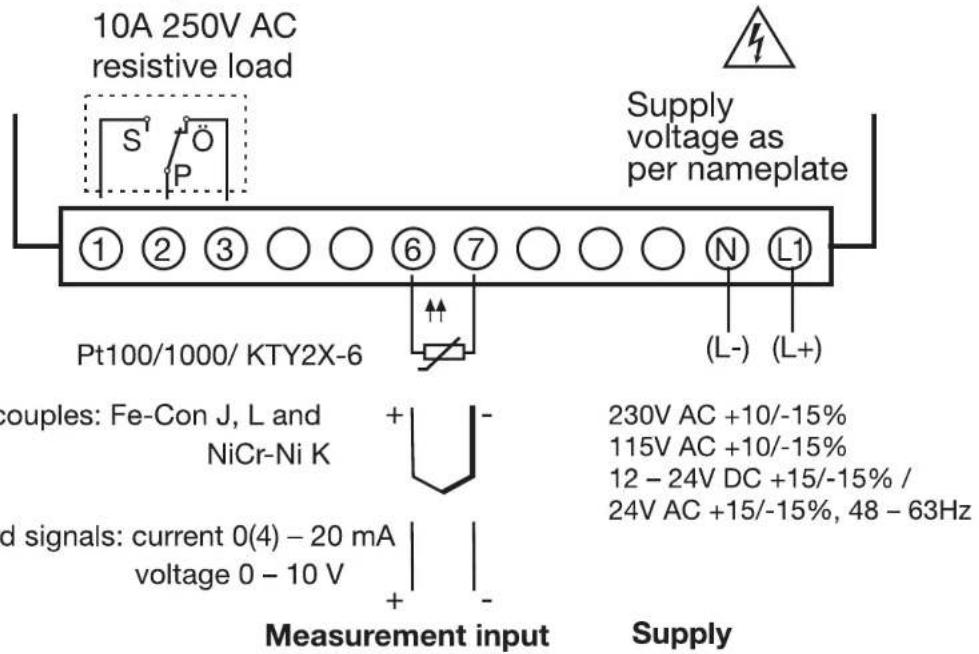
text_image
10A 250V AC resistive load S P Supply voltage as per nameplate ① ② ③ ○ ○ ⑥ ⑦ ○ ○ ○ N L1 Pt100/1000/ KTY2X-6 (L-) (L+) souples: Fe-Con J, L and NiCr-Ni K + - d signals: current 0(4) - 20 mA voltage 0 - 10 V Measurement input Supply 230V AC +10/-15% 115V AC +10/-15% 12 - 24V DC +15/-15% / 24V AC +15/-15%, 48 - 63Hz4 Commissioning the instrument
4.1 Displays and controls
| LC display | 3-digit segment display, 13 mm high, with symbols for °C, °F, min and s, with red background lighting | 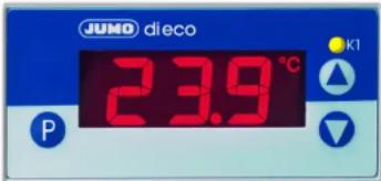 |
| Status displayKeys programming | LED K1 lights up when relay K1 is energized.LED K1 goes out when relay K1 is de-energized. | |
| increase parameter valueselect operational status in enabling leveldecrease parameter valueselect operational status in enabling levelversion displayexit, jump to basic status |  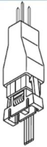 | |
| Setup interface | The instrument is linked to the PC via a PC interface with TTL/RS232 converter and adapter (3 pins). |
When everything is connected up correctly on the instrument, the present temperature is displayed. If an alarm message appears, see Chapter 6 "Alarm messages". The relay operates according to the selected relay type (out), see Chapter 4.3 "Setting the instrument functions (parameter level)".
4.2 Operating level

Time-out:
If no key is pressed for 30 seconds, then the instrument automatically switches back to the temperature display, see Overview of operation on the front inside page.
The parameters that have been enabled at the enabling level can be displayed and modified at the operating level.
* Press Ⓓ (only briefly). The first parameter that can be modified appears, e.g. and present value are displayed alternately.
Parameter name
* Use the ▲ and ▼ keys the set the value within the specified value range.
* Acknowledge settings with . Ⓓ
* Set the next parameter, see Overview of operation on the front inside page.
4.3 Setting the instrument functions (parameter level)

Time-out:
If no key is pressed for 60 seconds, the instrument automatically switches back to temperature display, see Overview of operation on the front inside page.
The instrument functions and values are set at the parameter level.
*Press for 3 seconds and will appear in alternation.
*Set code 72 for accessing the parameter level using the and keys. The longer the key is pressed, the faster the value will change.
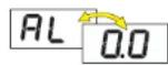
* Acknowledge with ,P parameter name and value appear alternately, e.g. AL 0.0
* Use the ▲ and ▼ keys to set the value within the specified value range.
* Acknowledge settings with . Ⓓ
* Set the next parameter, see Overview of operation on the front inside page.

Switching parameters out of display:
The table below lists all the parameters for each instrument type. Depending on the type designation on the nameplate, parameters that are not required are hidden.
Indicator parameters
| Parameter | Meaning | Value range from...factory-set...to |
| AL | Alarm value (limit for relay and LED)A measured value is considered to be an alarm if- present value is larger than alarm value AL + 12 hysteresis HYS and- has been continuously present for longer than configured under the alarm suppression time ALdAn alarm is reset if- present value is smaller than the alarm value - 12 hysteresis. | ALL ... 0 ... ALH |
| HYS | HysteresisIt is used to determine an alarm.The hysteresis lies symmetrically about the limit value AL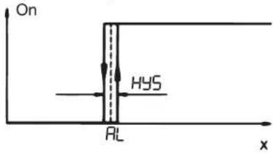 | 0.4 ... 1.0 ... 99.9°C/°F |
| ALL | Low alarm limitALL, together with RIs used to limit the value range for the alarm value AL. | -350 ... -200 ... 999°C/°F |
| ALH | High alarm limitALH, together with RIs used to limit the value range for the alarm value AL. | -350 ... 500 ... 999°C/°F |
| AL.d | Alarm suppression timeAn alarm is not considered to be an alarm for this period. The LED K1 flashes in the display. If an alarm is present for longer than then, it is considered to be an alarm, the LED K1 lights up and the relay is switched in accordance with the parameter (see parameter ). AL | 0 ... 60min |
| dLY | Switch-on delay after power-onFor the time-delayed switch-on of the alarm monitoring. No alarms are evaluated during this time, only probe errors. | 0 ... 60min |
| out | Relay type0: relay operates as a break contact in the event of an alarm1: relay operates as a make contact in the event of an alarm | 0 ... 1 |
| SEr | Response to over/underrange0: relay drops out at once1: relay pulls in at once | 0 ... 1 |
| Input | ||
| SEN | Sensor connected in 2-wire circuitMeasurement input group 1 on Type: 701540/X11-XX | Pt100: P.IhPt1000: P.ItKTY2X-6: PtC or tAb |
| Measurement input group 2 on Type: 701540/X21-XX Fe-Con J : | tcJFe-Con L: tc.LNiCr-Ni K: tc.Hor tAb | |
| Measurement input group 3 on Type: 701540/X31-XX | 0(4)... 20 mA:L in / tAb | |
| Measurement input group 4 on Type: 701540/X41-XX 0 ... 10 V: / | L in tAb | |
| S.cL | Start value for indication range with measurement input voltage or currentExample: input signal 4 — 20mA is to be represented in the display from -10 to 50. Set S.cL= -10 and S.cH=50. | -999 ... 0... +999 |
| S.cH | End value for indication range with measurement input voltage or current | -999 ... 100... +999 |
| I. O | Signal for measurement input current: 0 = 0 to 20mA1 = 4 to 20mA | 0, 1 |
| OF.t | Process value offsetPV offset in °C, °F or digit (no unit) | -99.9 ... 0.0 ... 99.9 |
| OF.r | Lead compensation resistanceThis value is used to compensate the resistance of the probe lead and is dependent on the lead length.For best temperature measurement results, the resistance value of the probe lead has to be entered here (with short-circuited probe).If the total resistance at the measurement input (sensor resistance + selected value for OF.r) exceeds 320Ω with Pt100 and 3200 Ω with Pt1000/KTY2x-6, a measurement error will occur ! | 0.0 ... 99.9 in Ω |
| Un i | Unitfor the process value displayedOnly the process value at the measurement input will be correspondingly converted when changing over to °F.All other variables will retain their values. | °C or °Fno (= no unit) |
| dF | Filter time constantfor adapting the digital input filter.At a signal step, 63% of the changes are registered after the filter time constant has elapsed.Values between 0.1 and 0.7 are interpreted as 0.8 (sampling time).If the filter time constant is long:- high damping of interference signals- slow reaction of the process value display to process value changes. | 0.1 ... 0.8 ... 99.9s |

Return to the first parameter AL of the parameter level with Ⓑ3 seconds.
4.4 Allocating user rights (enabling level)

Time-out:
If no key is pressed for 60 seconds, the instrument automatically switches back to the process value display, see Overview of operation on the front inside page.
The setting at the enabling level defines user rights which determine whether a parameter is shown at the operating level, can be edited or is not shown at all.
*Press for 3 seconds and appears
* Set code 82 for accessing the enabling level using the ▲ and ▼ keys.
* Acknowledge with Ⓓ Parameter and user right blink in alternation, e.g. AL Ed 1.
* Use the ▲ and ▼ keys to set user right to Ed, rd or no.
| User right Display Factory setting | ||
| Parameter is shown and editable | Ed, | AL |
| Parameter is shown only - | rd | |
| Parameter is not shown all other parameters | no |
* Acknowledge settings with . Ⓘ
* Set next parameter, see Overview of operation on the front inside page.
5 Technical data
| Meas. input Designation Meas. range | Meas. accuracy | ^1 /ambient temperature error | Recognition of ... | |
| Probe short-circuit | Probe break | |||
| Resistance thermometer | Pt100 EN 60751 | -200 to +600°C | 0.1%/ ≤100ppm/°C | recognized |
| Pt1000 EN 60751 | -200 to +600°C | 0.1%/ ≤100ppm/°C | recognized | |
| KTY2X-6 (PTC) | -50 to +150 °C | 1%/ ≤100ppm/°C | recognized | |
| resistance 0 — 3000 Ω | customer table ^3 | 0.1%/ ≤100ppm/°C ^3 | = 0Ω | |
| Measuring current with Pt100: 0.2 mA, with Pt1000, KTY2X-6 or resistance: 0.02 mA | ||||
| Lead compensation is adjustable via the parameter Lead compensation resistance OF.F.The total resistance (sensor+lead) must not exceed 320Ω with Pt100 and 3200Ω with Pt1000, KTY2X-6 or resistance. | ||||
| Thermo-couple | Fe-Con J EN 60584 | -200 to +999 °C | 0.4%/ ≤100ppm/°C ^2 | - |
| Fe-Con L DIN 43710 | -200 to +900 °C | 0.4%/ ≤100ppm/°C ^2 | - | |
| NiCr-Ni K EN 60584 | -200 to +999 °C | 0.4%/ ≤100ppm/°C ^2 | - | |
| -10 to 60 mV | customer table ^3 | 0.1%/ ≤100ppm/°C ^3 | - | |
| For the voltage input (-10 to 60 mV), terminal temperature compensation for thermocouples can be used. Internal terminal temperature compensation can be switched off through the setup program (0°C). | ||||
| Meas. input Designation Meas. range | Meas. accuracy | 1/ambient temperature error | Recognition of ... | |
| Probe short-circuit | Probe break | |||
| Current | 0 to 20 mA | -2 to 22 mAscalable withScL and ScHor customer table | 0.1%/ ≤100ppm/°C3 | - |
| 4 to 20 mA 2.4 to 21.6 mAscalable withScL and ScH | 0.1%/ ≤100ppm/°C3 | recognized recognized | ||
| Input resistance RIN≤ 3Ω | ||||
| Voltage | 0 to 10 V | -1 to 11 Vscalable withScL and ScHor customer table | 0.1%/ ≤100ppm/°C - | - |
| Input resistance RIN≥ 100kΩ | ||||
| 1.) The accuracy refers to the measuring range span.2.) valid from -50°C3.) A valid customer table must be entered through the setup program and switched over to In In instrument.This may reduce the measuring accuracy. | ||||
Ambient conditions
| Ambient temperature range | 0 to +55°C, with side-by-side mounting: 0 to +40°C |
| Storage temperature range -40 to +70°C | |
| Climatic conditions ≤ 75% rel. humidity, no condensation | |
| Cleaning and care of the front panel | The front panel can be cleaned with all the usual cleaning and rinsing agents.Do not use solvents such as methylated spirit, white spirit, P1 or xylene. |
Output
| Relay (changeover contact) 150,000 operations at 10A 250V AC resistive load |
Supply
| Supply voltage | 230V AC +10/-15%, 48 – 63Hz or 115V AC +10/-15%, 48 – 63Hz (electrically isolated from measurement input) |
| 12 – 24V DC +15/-15%, 24V AC +15/-15%, 48 – 63Hz (not electrically isolated from measurement input) | |
| Power consumption | < 3VA |
Housing
| Material | polycarbonate |
| Mounting | in panel cut-out with bezel seal |
| Operating position | unrestricted |
| Weight | approx. 160g |
| Protection | front IP65, rear IP20 |
| Flammability class | UL 94 VO |
Electrical data
| Data backup EEPROM | |
| Connection screw terminals for wire cross-sections up to 4 mm and up to 2.5 mm^2 stranded wire | ^2 solid wire |
| EMC- interference emission- immunitiy to interference | EN 61 326Class Bto industrial requirements |
| Operating conditions | The instrument is designed as a panel-mounting unit. |
| Electrical safety to EN 61 010, Part 1,overvoltage category III, pollution degree 2 | |
5.1 Setup program
The program and the interface with adapter are available as accessories and offer the following advantages:
- simple and convenient parameterization and archiving via PC
- simple duplicating of parameters on instruments of the same type
- possibility of entering a linearization table
Minimum hardware and software requirements
- PC Pentium 100 or compatible
- 128 MB RAM, 16 MB free on hard disk
- C D - R O M d r i v e
- free COM interface
- Microsoft Windows 98/ME/NT4.0/2000/XP
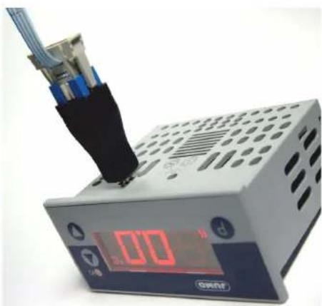
*Link PC interface to the RS232 interface on the PC
*Insert black adapter (3 pins) into instrument from below
natural_image
Digital industrial testing device with a black connector and red display showing 0.00, no visible text or symbols on the device itself.6 Alarm messages
The following alarm messages may appear in the temperature display:
| Error message Cause Elimination | ||
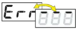 | Display overrunThe value is too large and is outside the range. | - Check sensor and connecting cable for damage or short-circuit- Check whether the correct sensor has been set or connected⇒ Chapter 4 “Commissioning the instrument” |
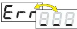 | Display underrunThe value is too small and is outside the range. | |
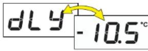 Current temp. Current temp. | Time for switch-on delay after power-on has elapsed.With display over/underrun,switch-on delay becomes ineffective. | *Cancel switch-on delay with Ⓓ ▼ |

JUMO GmbH & Co. KG
Street adress:
36039 Fulda, Germany
Delivery address:
Mackenrodtstraße 14
36039 Fulda, Germany
Postal address:
36035 Fulda, Germany
Phone: +49 661 6003-0
Fax: +49 661 6003-607
e-mail: mail@jumo.net
Internet: www.jumo.net
JUMO Instrument Co. Ltd.
JUMO House
Temple Bank, Riverway
Harlow, Essex CM20 2TT, UK
Phone: +44 1279 635533
Fax: +44 1279 635262
e-mail: sales@jumo.co.uk
Internet: www.jumo.co.uk
Operating Instructions
natural_image
Digital industrial machine with a black connector and red LED display showing 0.00, no visible text or symbols on the device itself.6 Messages d'erreur
36039 Fulda, Germany
Lieferadresse:
Mackenrodtstraße 14
36039 Fulda, Germany
Postadresse:
36035 Fulda, Germany
Telefon: 0661 6003-0
Telefax: 0661 6003-500
E-Mail: mail@jumo.net
Internet: www.jumo.net
JUMO Régulation S.A.
Actipôle Borny
7 rue des Drapiers
B.P. 45200
57075 Metz - Cedex 3, France